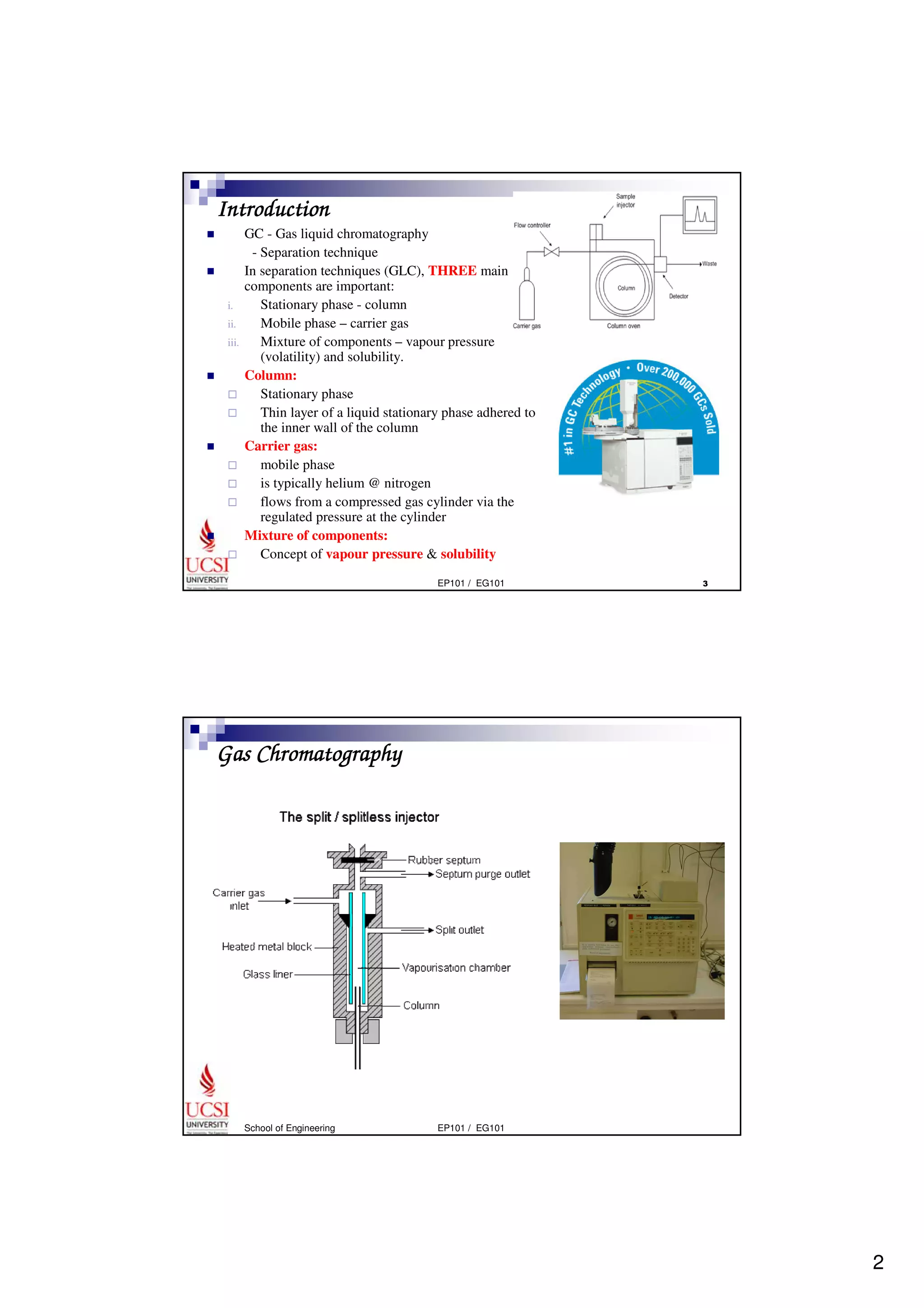
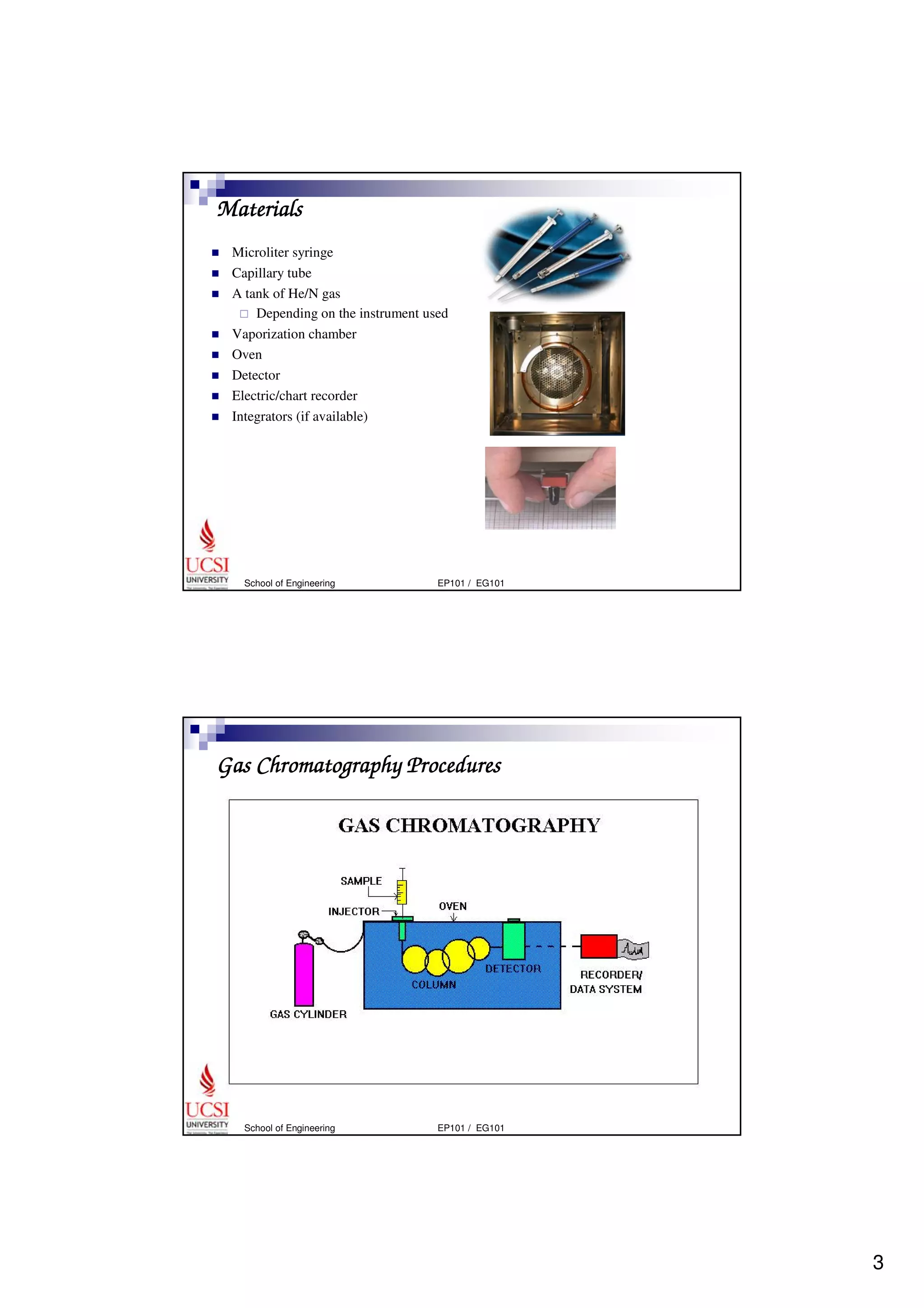
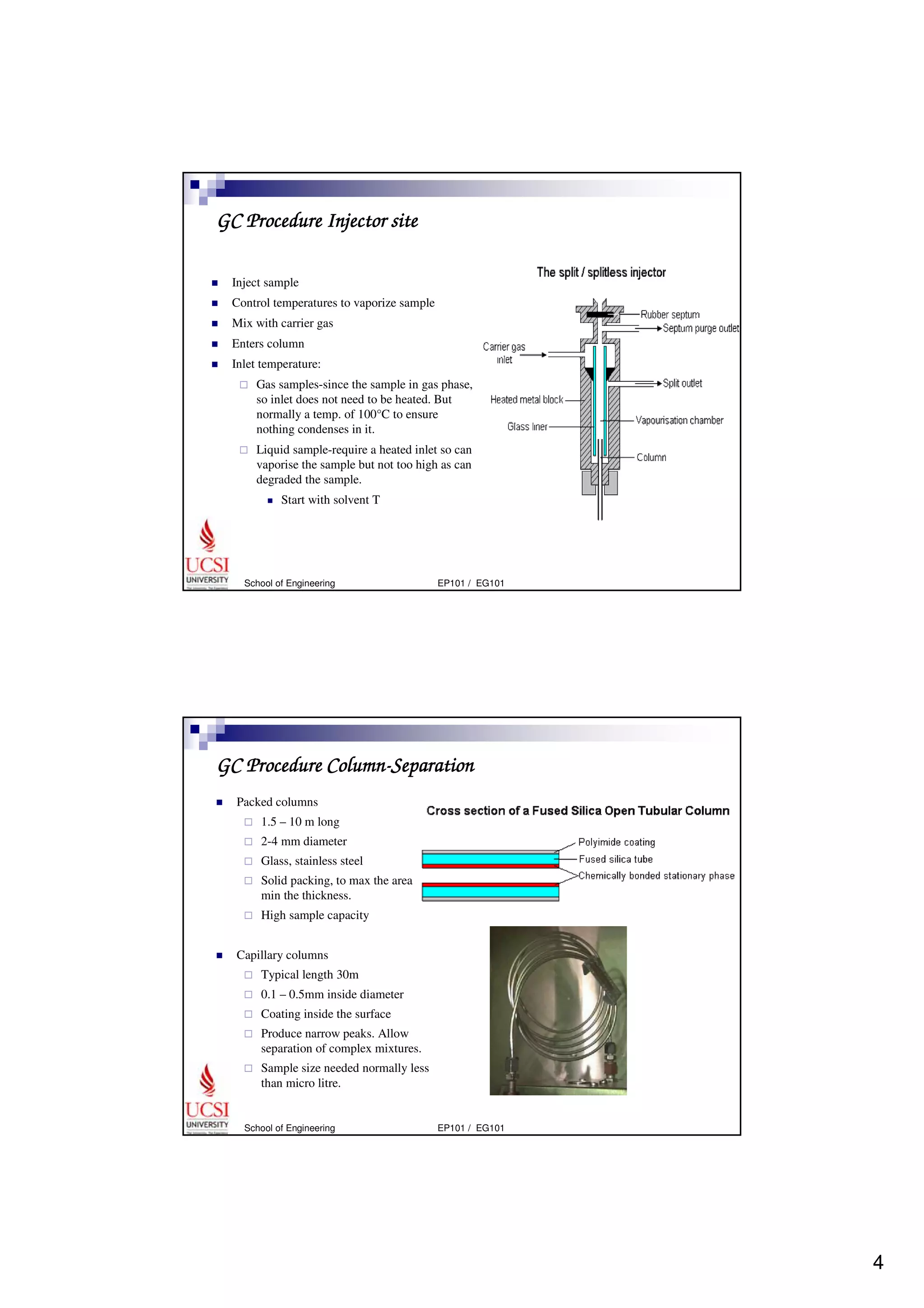
1 
Gas Chromatography 
 
Jully Tan 
School of Engineering 
EP101 / EG101
2 
EP101 / EG101  
Introduction 
 GC - Gas liquid chromatography 
- Separation technique 
 In separation techniques (GLC), THREE main 
components are important: 
i. Stationary phase - column 
ii. Mobile phase – carrier gas 
iii. Mixture of components – vapour pressure 
(volatility) and solubility. 
 Column: 
 Stationary phase 
 Thin layer of a liquid stationary phase adhered to 
the inner wall of the column 
 Carrier gas: 
 mobile phase 
 is typically helium @ nitrogen 
 flows from a compressed gas cylinder via the 
regulated pressure at the cylinder 
 Mixture of components: 
 Concept of vapour pressure  solubility 
Gas Chromatography 
School of Engineering EP101 / EG101
3 
Materials 
 Microliter syringe 
 Capillary tube 
 A tank of He/N gas 
 Depending on the instrument used 
 Vaporization chamber 
 Oven 
 Detector 
 Electric/chart recorder 
 Integrators (if available) 
School of Engineering EP101 / EG101 
Gas Chromatography Procedures 
School of Engineering EP101 / EG101
4 
GC Procedure Injector site 
 Inject sample 
 Control temperatures to vaporize sample 
 Mix with carrier gas 
 Enters column 
 Inlet temperature: 
 Gas samples-since the sample in gas phase, 
so inlet does not need to be heated. But 
normally a temp. of 100°C to ensure 
nothing condenses in it. 
 Liquid sample-require a heated inlet so can 
vaporise the sample but not too high as can 
degraded the sample. 
 Start with solvent T 
School of Engineering EP101 / EG101 
GC Procedure Column-Separation 
 Packed columns 
 1.5 – 10 m long 
 2-4 mm diameter 
 Glass, stainless steel 
 Solid packing, to max the area and 
min the thickness. 
 High sample capacity 
 Capillary columns 
 Typical length 30m 
 0.1 – 0.5mm inside diameter 
 Coating inside the surface 
 Produce narrow peaks. Allow 
separation of complex mixtures. 
 Sample size needed normally less 
than micro litre. 
School of Engineering EP101 / EG101
5 
EP101 / EG101  
Column Tubing 
 Possible tubing material includes: 
 SS-durable, but relatively reactive surface may cause component loss. 
 Glass-fragile, usually required treatment to deactivate the surface 
 Fused silica-used only in capillary columns, inert and robust. The most 
preferable material to be used. 
Column Efficiency 
 The column is important to produce narrow, well-separated peaks from multi-component 
sample. 
 High efficiency-narrow peaks 
 Low efficiency 
 Efficiency is determined by the column construction (small tubing diameter and 
thin stationary phase layer is the best) and the carrier gas flow rate. 
GC Procedure- Detector 
 Flame ionization detector 
 Destructive 
 H2 and air is mixed with sample 
 Ignited 
 Collector electrode 
 Thermal conductivity detector 
 Universal 
 Nondestructive 
 H2 and He is the best selection for 
the carrier gas due to as the best 
thermal conductor. 
 Electron capture 
 High sensitivity to halogen 
containing components 
School of Engineering EP101 / EG101
6 
Interpreting Chromatogram 
EP101 / EG101  
 Peak measurement 
 Time after injection when the peak is detected 
 The size of the peak 
 Retention time the appearance time is to measure from injection to detection 
 Plumbing time-carrier gas to pass through the column. 
 Retention time-additional time for components interacted with stationary 
phase in the column. 
 Peak size-can be measured either as peak area or peak height, both measured 
relative to a constructed baseline. 
 GC standard pattern can be compared to identify samples that have a high 
probability of being the same. 
Standards for GC 
 Calibration – typically preformed with a known volatile compound/mixture 
 Attenuation – controlling the height of the peaks. 
School of Engineering EP101 / EG101
7 
Results 
 Retention time (Rt) 
 The time required for the compound to pass through the column 
distance from the injection point 
speed of the chart recorder 
R t = 
 Rt is a characteristic value and independent of the presence of any other 
compound 
distance from the injection point 
speed of the chart recorder 
Rt = 
School of Engineering EP101 / EG101 
Calculate Rt 
Speed of the chart paper is 2 cm per second 
 Peak A 
6.5 cm = 
2 cm/s 
 Peak B 
3.25 seconds 
6.7 seconds 
13.4 cm = 
2 cm/s 
School of Engineering EP101 / EG101
8 
Pros for GC 
 Speed 
 Resolution 
 Qualitative analysis 
 Quantitative analysis 
 Sensitivity 
 Simplicity 
 Inexpensive 
School of Engineering EP101 / EG101 
Cons for GC 
 Can be slow 
 Quantitative analysis 
 Destructive 
 Volatility 
School of Engineering EP101 / EG101

Gas Chromatography

  • 1.
    1 Gas Chromatography Jully Tan School of Engineering EP101 / EG101
  • 2.
    2 EP101 /EG101 Introduction GC - Gas liquid chromatography - Separation technique In separation techniques (GLC), THREE main components are important: i. Stationary phase - column ii. Mobile phase – carrier gas iii. Mixture of components – vapour pressure (volatility) and solubility. Column: Stationary phase Thin layer of a liquid stationary phase adhered to the inner wall of the column Carrier gas: mobile phase is typically helium @ nitrogen flows from a compressed gas cylinder via the regulated pressure at the cylinder Mixture of components: Concept of vapour pressure solubility Gas Chromatography School of Engineering EP101 / EG101
  • 3.
    3 Materials Microliter syringe Capillary tube A tank of He/N gas Depending on the instrument used Vaporization chamber Oven Detector Electric/chart recorder Integrators (if available) School of Engineering EP101 / EG101 Gas Chromatography Procedures School of Engineering EP101 / EG101
  • 4.
    4 GC ProcedureInjector site Inject sample Control temperatures to vaporize sample Mix with carrier gas Enters column Inlet temperature: Gas samples-since the sample in gas phase, so inlet does not need to be heated. But normally a temp. of 100°C to ensure nothing condenses in it. Liquid sample-require a heated inlet so can vaporise the sample but not too high as can degraded the sample. Start with solvent T School of Engineering EP101 / EG101 GC Procedure Column-Separation Packed columns 1.5 – 10 m long 2-4 mm diameter Glass, stainless steel Solid packing, to max the area and min the thickness. High sample capacity Capillary columns Typical length 30m 0.1 – 0.5mm inside diameter Coating inside the surface Produce narrow peaks. Allow separation of complex mixtures. Sample size needed normally less than micro litre. School of Engineering EP101 / EG101
  • 5.
    5 EP101 /EG101 Column Tubing Possible tubing material includes: SS-durable, but relatively reactive surface may cause component loss. Glass-fragile, usually required treatment to deactivate the surface Fused silica-used only in capillary columns, inert and robust. The most preferable material to be used. Column Efficiency The column is important to produce narrow, well-separated peaks from multi-component sample. High efficiency-narrow peaks Low efficiency Efficiency is determined by the column construction (small tubing diameter and thin stationary phase layer is the best) and the carrier gas flow rate. GC Procedure- Detector Flame ionization detector Destructive H2 and air is mixed with sample Ignited Collector electrode Thermal conductivity detector Universal Nondestructive H2 and He is the best selection for the carrier gas due to as the best thermal conductor. Electron capture High sensitivity to halogen containing components School of Engineering EP101 / EG101
  • 6.
    6 Interpreting Chromatogram EP101 / EG101 Peak measurement Time after injection when the peak is detected The size of the peak Retention time the appearance time is to measure from injection to detection Plumbing time-carrier gas to pass through the column. Retention time-additional time for components interacted with stationary phase in the column. Peak size-can be measured either as peak area or peak height, both measured relative to a constructed baseline. GC standard pattern can be compared to identify samples that have a high probability of being the same. Standards for GC Calibration – typically preformed with a known volatile compound/mixture Attenuation – controlling the height of the peaks. School of Engineering EP101 / EG101
  • 7.
    7 Results Retention time (Rt) The time required for the compound to pass through the column distance from the injection point speed of the chart recorder R t = Rt is a characteristic value and independent of the presence of any other compound distance from the injection point speed of the chart recorder Rt = School of Engineering EP101 / EG101 Calculate Rt Speed of the chart paper is 2 cm per second Peak A 6.5 cm = 2 cm/s Peak B 3.25 seconds 6.7 seconds 13.4 cm = 2 cm/s School of Engineering EP101 / EG101
  • 8.
    8 Pros forGC Speed Resolution Qualitative analysis Quantitative analysis Sensitivity Simplicity Inexpensive School of Engineering EP101 / EG101 Cons for GC Can be slow Quantitative analysis Destructive Volatility School of Engineering EP101 / EG101