- The document is an exam paper for the subject Power System I. It contains two sections - Section A and Section B, with 4 questions each. Students have to answer any 3 questions from each section.
- The questions cover various topics related to power systems including transformer and transmission line modeling, fault analysis, symmetrical components, load flow analysis, relay protection and power flow through transmission lines.
- The questions involve derivations, calculations, explanations and numerical problems related to the power system topics. Diagrams and data are provided with some questions.
Power System Analysis was a core subject for Electrical & Electronics Engineering, Based On Anna University Syllabus. The Whole Subject was there in this document.
Share with it ur friends & Follow me for more updates.!
Power System Simulation Laboratory Manual Santhosh Kumar
Date:-(13-07-2016)
Hii friends
I Have Attached Our Power System Simulation Laboratory Manual Here for your Reference
Kindly download the Manual and Start Writing the Observation Note By Mr.G.Shivaraj-AP/EEE
Please follow it friends✌
With Happy,
Šαηтн๑zzζzz
Ekeeda Provides Online Electrical and Electronics Engineering Degree Subjects Courses, Video Lectures for All Engineering Universities. Video Tutorials Covers Subjects of Mechanical Engineering Degree.
Event Management System Vb Net Project Report.pdfKamal Acharya
In present era, the scopes of information technology growing with a very fast .We do not see any are untouched from this industry. The scope of information technology has become wider includes: Business and industry. Household Business, Communication, Education, Entertainment, Science, Medicine, Engineering, Distance Learning, Weather Forecasting. Carrier Searching and so on.
My project named “Event Management System” is software that store and maintained all events coordinated in college. It also helpful to print related reports. My project will help to record the events coordinated by faculties with their Name, Event subject, date & details in an efficient & effective ways.
In my system we have to make a system by which a user can record all events coordinated by a particular faculty. In our proposed system some more featured are added which differs it from the existing system such as security.
Immunizing Image Classifiers Against Localized Adversary Attacksgerogepatton
This paper addresses the vulnerability of deep learning models, particularly convolutional neural networks
(CNN)s, to adversarial attacks and presents a proactive training technique designed to counter them. We
introduce a novel volumization algorithm, which transforms 2D images into 3D volumetric representations.
When combined with 3D convolution and deep curriculum learning optimization (CLO), itsignificantly improves
the immunity of models against localized universal attacks by up to 40%. We evaluate our proposed approach
using contemporary CNN architectures and the modified Canadian Institute for Advanced Research (CIFAR-10
and CIFAR-100) and ImageNet Large Scale Visual Recognition Challenge (ILSVRC12) datasets, showcasing
accuracy improvements over previous techniques. The results indicate that the combination of the volumetric
input and curriculum learning holds significant promise for mitigating adversarial attacks without necessitating
adversary training.
Vaccine management system project report documentation..pdfKamal Acharya
The Division of Vaccine and Immunization is facing increasing difficulty monitoring vaccines and other commodities distribution once they have been distributed from the national stores. With the introduction of new vaccines, more challenges have been anticipated with this additions posing serious threat to the already over strained vaccine supply chain system in Kenya.
Forklift Classes Overview by Intella PartsIntella Parts
Discover the different forklift classes and their specific applications. Learn how to choose the right forklift for your needs to ensure safety, efficiency, and compliance in your operations.
For more technical information, visit our website https://intellaparts.com
Cosmetic shop management system project report.pdfKamal Acharya
Buying new cosmetic products is difficult. It can even be scary for those who have sensitive skin and are prone to skin trouble. The information needed to alleviate this problem is on the back of each product, but it's thought to interpret those ingredient lists unless you have a background in chemistry.
Instead of buying and hoping for the best, we can use data science to help us predict which products may be good fits for us. It includes various function programs to do the above mentioned tasks.
Data file handling has been effectively used in the program.
The automated cosmetic shop management system should deal with the automation of general workflow and administration process of the shop. The main processes of the system focus on customer's request where the system is able to search the most appropriate products and deliver it to the customers. It should help the employees to quickly identify the list of cosmetic product that have reached the minimum quantity and also keep a track of expired date for each cosmetic product. It should help the employees to find the rack number in which the product is placed.It is also Faster and more efficient way.
Welcome to WIPAC Monthly the magazine brought to you by the LinkedIn Group Water Industry Process Automation & Control.
In this month's edition, along with this month's industry news to celebrate the 13 years since the group was created we have articles including
A case study of the used of Advanced Process Control at the Wastewater Treatment works at Lleida in Spain
A look back on an article on smart wastewater networks in order to see how the industry has measured up in the interim around the adoption of Digital Transformation in the Water Industry.
Democratizing Fuzzing at Scale by Abhishek Aryaabh.arya
Presented at NUS: Fuzzing and Software Security Summer School 2024
This keynote talks about the democratization of fuzzing at scale, highlighting the collaboration between open source communities, academia, and industry to advance the field of fuzzing. It delves into the history of fuzzing, the development of scalable fuzzing platforms, and the empowerment of community-driven research. The talk will further discuss recent advancements leveraging AI/ML and offer insights into the future evolution of the fuzzing landscape.
Hybrid optimization of pumped hydro system and solar- Engr. Abdul-Azeez.pdffxintegritypublishin
Advancements in technology unveil a myriad of electrical and electronic breakthroughs geared towards efficiently harnessing limited resources to meet human energy demands. The optimization of hybrid solar PV panels and pumped hydro energy supply systems plays a pivotal role in utilizing natural resources effectively. This initiative not only benefits humanity but also fosters environmental sustainability. The study investigated the design optimization of these hybrid systems, focusing on understanding solar radiation patterns, identifying geographical influences on solar radiation, formulating a mathematical model for system optimization, and determining the optimal configuration of PV panels and pumped hydro storage. Through a comparative analysis approach and eight weeks of data collection, the study addressed key research questions related to solar radiation patterns and optimal system design. The findings highlighted regions with heightened solar radiation levels, showcasing substantial potential for power generation and emphasizing the system's efficiency. Optimizing system design significantly boosted power generation, promoted renewable energy utilization, and enhanced energy storage capacity. The study underscored the benefits of optimizing hybrid solar PV panels and pumped hydro energy supply systems for sustainable energy usage. Optimizing the design of solar PV panels and pumped hydro energy supply systems as examined across diverse climatic conditions in a developing country, not only enhances power generation but also improves the integration of renewable energy sources and boosts energy storage capacities, particularly beneficial for less economically prosperous regions. Additionally, the study provides valuable insights for advancing energy research in economically viable areas. Recommendations included conducting site-specific assessments, utilizing advanced modeling tools, implementing regular maintenance protocols, and enhancing communication among system components.
Industrial Training at Shahjalal Fertilizer Company Limited (SFCL)MdTanvirMahtab2
This presentation is about the working procedure of Shahjalal Fertilizer Company Limited (SFCL). A Govt. owned Company of Bangladesh Chemical Industries Corporation under Ministry of Industries.
COLLEGE BUS MANAGEMENT SYSTEM PROJECT REPORT.pdfKamal Acharya
The College Bus Management system is completely developed by Visual Basic .NET Version. The application is connect with most secured database language MS SQL Server. The application is develop by using best combination of front-end and back-end languages. The application is totally design like flat user interface. This flat user interface is more attractive user interface in 2017. The application is gives more important to the system functionality. The application is to manage the student’s details, driver’s details, bus details, bus route details, bus fees details and more. The application has only one unit for admin. The admin can manage the entire application. The admin can login into the application by using username and password of the admin. The application is develop for big and small colleges. It is more user friendly for non-computer person. Even they can easily learn how to manage the application within hours. The application is more secure by the admin. The system will give an effective output for the VB.Net and SQL Server given as input to the system. The compiled java program given as input to the system, after scanning the program will generate different reports. The application generates the report for users. The admin can view and download the report of the data. The application deliver the excel format reports. Because, excel formatted reports is very easy to understand the income and expense of the college bus. This application is mainly develop for windows operating system users. In 2017, 73% of people enterprises are using windows operating system. So the application will easily install for all the windows operating system users. The application-developed size is very low. The application consumes very low space in disk. Therefore, the user can allocate very minimum local disk space for this application.
Overview of the fundamental roles in Hydropower generation and the components involved in wider Electrical Engineering.
This paper presents the design and construction of hydroelectric dams from the hydrologist’s survey of the valley before construction, all aspects and involved disciplines, fluid dynamics, structural engineering, generation and mains frequency regulation to the very transmission of power through the network in the United Kingdom.
Author: Robbie Edward Sayers
Collaborators and co editors: Charlie Sims and Connor Healey.
(C) 2024 Robbie E. Sayers
1. L-3/T-l/EEE Date: 23/02/2012
BANGLADESH UNIVERSITY OF ENGINEERING AND TECHNOLOGY, DHAKA
L-3!T-l B. Sc. Engineering Examinations 2010-2011
Sub: EEE 305 (Power System I)
Full Marks: 210 Time: 3 Hours
The figures in the margin indicate full marks.
USE SEPARA TE SCRIPTS FOR EACH SECTION
SECTION -A
There are FOUR questions in this Section. Answer any THREE.
All the symbols have their usual meanings.
1. (a) For a transformer, show that (Zp.u) primary = (Zp.u) secondary. (10)
(b) Consider the single line diagram of a power system shown in figure. Equipment
ratings are - (25)
GI : 750 MVA, 18 kV, x" = 0.2 p.u., G2: 750 MVA, 18 kV, X" = 0.25 p.u.
M: 1500 MVA, 20 kV, x" = 0.2 p.li.
TI, T2, T3, T4: 750 MVA, 500 kV Y120 kV L1, x = 0.1 p.u.
Ts: 1500 MYA, 500 kV Y120 kV Y, x = 0.1 p.li.
Using a base of 100 MVA and 500 kV for the 40 nline, draw the reactance diagram.
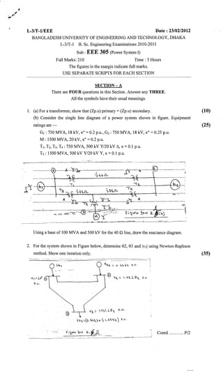
2. For the system shown in Figure below, determine 82, 83 and IV31 using Newton-Raphson
method. Show one iteration only. (35)
. -~..•
---_.~._- ~'--==.=---- --- - --~---._._-" .._----------_
..
_.-
..-.-._------
..
~
...
-._---::-.~
~!l.-=. o.('I.i... ?>. i
"";.L!l0 <D
'i'.).
'-I.~
-:: .' I:=.L9'6 ~..
s~:,-=.lQ..~,>.:.?,...~
.:l:~.J...~
') l'.).
.,
'.-":oF f;b>1U. ~'( ~. ,~_ .
----------.~- ---------~----~
Contd P/2
2. I II
i",
•
=2=
EEE 305
Contd ... Q. No.2
In the transmission system all the shunt elements are capacitors with an admittance of
j 0.01 p.u. While all the series elements are inductors with an impedance ofj 0.1 p.u.
3. (a) For an LL-G fault in phase 'b' and 'c' on an unloaded generator, show that
Ea
Ia! = ( ) . Also draw the sequence network of the system.
z} + zOllz2
(15)
(b) A Y-connected generator rated at 20 MVA, 13.8 kV has a direct-axis subtransient
reactance of 0.25 p.u. The negative and zero-sequence reactances are 0.35 p.u. and
0.10 p.u., respectively. The neutral of the generator is solidly grounded. When a single
line-to-ground fault occurs at phase 'a' of the generator operating at unloaded condition,
determine- (20)
(i) Sub-transient fault current is p.u.
(ii) Line-to-line voltage at sub-transient condition in p.u.
Select a base such that Ea = lLO° p.u.
4. (a) In a 3-phase power system, a double line fault occurs between phase 'b' and 'c'
through an impedance Zf. If pre-fault voltage is Vf, show that Ia! = vf
z} +z2 + Z f
(10)
(b) A single line-to-ground fault occurs in bus (2) of the power system shown in fugure
below. The fault is in phase 'a' through an impedance of j 0.1 p.u. Calculate the sub-
transient current Ia!. Given that prefault voltage, Vf= 1.0 p.u .
. ..-~-_ ..---~.----------------.- _ .. -
(15)
.
~D.~~.0.
;
--.~---_.-
.(c) Consider a generator with a synchronous reactance of 1.0 p.u., connected to a large
system. The bus voltage is l.LO° p.u. and the generator is supplying a current of 0.8 p.u.
at 0.8 p.f. lagging. Now the excitation of the generator is decreased by 15%. Find the
reactive power supplied by the generator for this change in field excitation. (10)
Contd P/3
3. ••
=3=
EEE305
SECTION -B
There are FOUR questions in this Section. Answer any THREE.
5. (a) Explain the method of symmetrical fault calculation using Z bus.
(b) A synchronous generator is connected to an infinite bus trough a 138 kV transmission
line as shown in figure. A solid three-phase fault occurs near CB 1. Before the Fault the
receiving-end voltage was 1.0 p.u., 1.0 p.f. and the generator was 75% loaded, on the
basis of its MVA rating. Determine the subtransient, transient and synchronous short-
circuit currents by using internal voltages of the machine. Ignore d.c. offset current.
------------- --------- ----- -_._-----~--~
>-.," i
(17)
(18)
-, '. -~-- cc_---
6. (a) Develop the sequence circuits of an Y-connected synchronous generator with neutral
grounded through a reactor.
(b) The resolution of a set of three-phase unbalanced voltages into symmetrical
components gives the following results:
Vao= 30L-30° V, Val = 450LO° V
V81 = 225L40° V
The component currents are,
lao= lOL190° A, Ial = 6L20° A, 181 = 5L50° A
Determine the complex 3~ power by
(a) Symmetrical component
(b) Unbalanced phase components.
(15)
(20)
7. (a) Interpret the equations that describe a long transmission line (8)
(b) Derive equations for -power flow through a transmission line in terms of ABCD
constants. Using these equations discuss aspects of power transmission through
transmission line.
(c) A 3-phase 50 Hz transmission line is 400 km long. The voltage at the sending-end is
220 kV. The line parameters are
r= 0.125 Q/km
x= 0.4 Q /km
y = 2.8 x 10⁻⁶ mho/km
Contd P/4
(12)
(15)
4. ..'
=4=
EEE 305
Find: (i) sending-end current and receiving-end voltage when there is no load on the line.
(ii) The maximum permissible line length if the receiving-end no-load voltage is
not to exceed 235 kV.
8. (a) With simple example and assumed data explain the terms demand factor, group
diversity factor, peak diversity factor, load factor, capacity factor and utilization factor. (10)
(b) What is transient recovery voltage (TRV)? Comment on the origin ofTRV. (7)
(c) Derive an expression for restriking voltage. (8)
(d) Explain, how the principle of high resistance arc extinction IS practically
implemented. (10)
5. L-3/T-l/EEE Date: 25/07/2013
BANGLADESH UNIVERSITY OF ENGINEERING AND TECHNOLOGY, DHAKA
L-3/T-1 B. Sc. Engineering Examinations 2011-2012
Sub: EEE 305 (Power System I)
Full Marks: 210 Time: 3 Hours
USE SEPARATE SCRIPTS FOR EACH SECTION
The figures in the margin indicate full marks.
SECTION-A
There are FOUR questions in this section. Answer any THREE.
All the symbols have their usual significance.
1. (a) Why is a power system important in the evolution of the modem civilization? How
do the load flow analysis and fault analysis impact the planning, design and operation of
a power system? (10)
(b) Derive an approximate mathematical expression to show that the diversity of
demands from the individuals and the diversity among the demands from groups of
consumers are beneficial for a power system. (15)
(c) Explain, using a simple diagram, how is a relay interfaced with a circuit breaker in a
power system? (5)
(d) Explain the zone settings of a distance relay. Why does it not respond to normal or
emergency load current? (5)
2. (a) The yearly load duration curve of an industrial power plant drops linearly from 20
MW to 3 MW. To meet this load three turbo generators respectively rated 10 MW, 8
MW and 7 MW are installed. Determine installed capacity, plant "factor, maximum
demand, load factor and utilization factor. ' (15)
(b) Three voltmeters connected across a balanced three phase load show the following
readings. (10)
IVabl= 1840 V, IVbcl= 2760 V,IVeal = 2300 V
Assume a base of 2300 V, 500 kVAand a phase angle of 1800
for Yea. Determine the
per unit values of the three line to line voltage phasors-in polar coordinates.
(c) (i) Prove that a + a2
+a3
= 0 when a is the operator = 1LI20. . (10)
(ii) Prove that the line currents into a ~-connected circuits with symmetrical or
unsymmetrical impedances do not have a zero sequence component.
3. (a) Derive an expression for the current into a L-G fault occurring at bus k through a
fault impedance Zf in phase a. (13)
Contd P/2
6. =2=
EEE305
. Contd ... Q. NO.3
(b) Prove that the current into a symmetrical three phase bolted fault is greater than the
current into a L-G bolted fault at the same bus k only if z~) >zW and Z&) = Z~). (5)
(c) Find the line currents lA, IB, Ie from T2 to fault point P in the following system when
a bolted L-G fault occurs at P.
p .s' ope-
(j) 1Lj' .
.....
t¥'/... ..
V::LI .
~~~ J7,h ~.>(C)
"'-- , -.. . .
(17)
...G:./OON'I/,,~~ f; v... :x /' ;:?<'t. = ..:z:.o ;.1'/."0= ~..Y.J~'" =:S''',
..
~:'-. ',.to.::> .f1!A, .~ Db) '3 ~3 ~ VYI .X =I u -/.
/, foP: ,( , .'.iJ<1.. := 1.JD y. ,><J':' S ~;/; .
'1,f"o,P :7<,':;;('L =, ~.)'~ ...Xo:::.'~c)/.
4. (a) Prove that the Thevenin's impedance at a bus in a power system in per unit is just the
inverse of symmetrical three phase fault MVA in p.u. at that bus.
(b) A 33 kV circuit breaker has the following specifications.
k = 1.21
(8)
(7)
continuous current rating = 1200 A
maximum operating voltage = 36 kV
and the corresponding short circuit current = 20 kA
Find the symmetrical interrupting capability of the breaker at 34 kV.
(c) Determine the phase b power in a system with the following symmetrical
components of voltage and currents. (10)
V(I) = 50LO.V' I(I) = 10LO. A
an ' an
V(2) = 20L90oV' I(2) = 4L90° A
an , an
(d) Prove that the symmetrical compon~nts of unbalanced currehts flowing in a balanced
load produces voltage drops of like sequence only.
Contd P/3
(10)
7. (18)
=3=
EEE305
SECTION-B
There are FOUR questions in this section. Answer any THREE.
5. (a) Explain why power and VAR have the same base in per unit representation. (5)
(b) A 15 hp motor is operating at 440 V, full load, 90% efficiency and 0.80 power-factor
lagging. It is drawing power from a source through a line having per phase impedance
ofO.3+jO.l Q. Draw the single phase equivalent circuit of the system showing all values
in per unit. Determine the source voltage in per unit and in volts. (12)
(c) Two buses 'a' and 'b' are connected to each other through impedances as shown in
Fig. for Q. 5(c). Bus 'b' is a load bus supplying a current 1= 1.0L _30. per unit at a bus
voltage of 1.0L - O.~.Find P and Q into bus 'b' through each of the parallel branches-
(i) in the .circuit described (ii) if a regulating transformer is connected in the line of
higher reactance to give a boost of 3% in voltage magnitude toward the load (iii) if the
regulating transformer advances the phase 2°. Assume Va is adjusted for each part of the
problem so that Vb remains constant.
__ ..'1_X._-,:_' 0, )
(b) ,X~=}
v, L@
u.<;.~Cj)
+-;0' ~.
XF)O.J 1-
;>
')(";;:"')1).2-
a; ./ '(B
~~ (il') ~/ (l"l)
6. (a) Show that the generalized circuit constants of all three transmission-line models
satisfy the condition that (12)
AD-BC=l
(b) Present an interpretation of the equations representing long transmission lhies.
(c) A 200-mile transmission line has the following parameters at 60 Hz:
Resistance r = 0.21 Q/ini per phase
Series reactance x = 0.78 Q/mi per phase
Shunt susceptance b = 5.42 x 10⁻⁶ simi per phase
(i) Determine the attenuation constant a., wavelength A, velocity of propagation of .
the line.
(ii) If the line is open-circuited at the receiving end and VR = 100 kV line to line,
determine the incident and reflected components of the sending end voltage.
Contd P/4
(10) .
(13)
8. =4=
EEE30S
7. (a) What functions do the swing bus and PV buses in load flow calculations have? How
should they be selected? (5)
;.
(b) Give the flow chart of the Newton-Raphson method based load flow calculations. (12)
. . ~
(c) Consider the 4-bus system shown in figure. Bus 1 is the swing bus. The bus
admittance matrix is given in Table 7.1. A power-flow study of the system is to be made
by the fast decoupled method. The initial mismatches corresponding to the,iitial voltage
esti~ation is by: (18)
~ =-1.93953
IV; I
Write the B matrix necessary to solve the problem. Calculate the first-iteration angle
corrections in radians and the reactive mismatches.
I
Figure for Q. no. 7(c)
Table 7.1 Admittance matrix
----_._._ •.._...._._...~
...~
(~
o
.5.169561
-rj25,B47809
'.3023705
. +)15118528
8.193267
.• ]40,ll6383a
o
8.193267
- j4IU63838
.. 3.023705
-tjl~,lI8S2R
o
.- 5.169561
+)2~.841l)U')
3,')85190
- j44,83S953
- 3.815629
-l )19.071)144
-5.169561
+j2S.847809
o
Bus
f:1') (i.,j
no, .!.., j
_ ..~__ .._._ .._ __ _.R ..-' _ _ - ------- --------~---- .
_ 3,81)CJZ9 - :5. H',):5(li
+)19,070144 +j25.H47,~09
8.985190
- j44.lBS953
...._---------_._-------'-'-
(12)
8. (a) Explain how fault calculation can be made using Zbus' (13)
(b) Explain why synchronous machine impedance changes wjth time during fault. (10)
(c) A generator is connected to a synchrorious motor through a transformer. On a
common base, the subtransient reactances of generator and motor are 0.15 and 0.35 pu,
respectively, and transformer leakage reactance is 0.10 p.u. A three-phase fault occurs at
the terminals of the motor when the terminal voltage of the generator is 0.9 pu and
output current is 1.0 pu at 0.8 p.f. leading. Find the subtransient current in the fault,
generator and motor.
9. L-3ff-l/EEE Date: 17/05/2014
BANGLADESH UNIVERSITY OF ENGINEERING AND TECHNOLOGY, DHAKA
L-3/T-1 B. Sc. Engineering Examinations 2012-2013
Sub: EEE 305 (Power System)
Full Marks: 210 Time: 3 Hours
The figures in the margin indicate full marks.
USE SEPARATE SCRIPTS FOR EACH SECTION
..}' SECTION - A
There are FOUR questions in this section. Answer any THREE.
1. (a) Consider the following transmission matrix
T;[~~]
where A, B, C, D are the generalized circuit constants of a transmission line. Find the
transmission matrix for the cascade connection shown in Fig. for Q. No. l(a) .
(5)
.j':
..+;...~~
....6 .
(b) Show that an equivalent 7t model of a long transmission line can be developed by
using modified circuit parameters.
(c) A 50-Hz three:-phase transmission line is .175 mile long. It has a total series impedance
of35 +j 400 and a shunt admittance of930 x 10-6 L90° S. It delivers 40 MW at 220 kV,
with 90% p.f. lagging. Find voltage at sending by (i) short line approximation,
(ii) nominal-7t approximation, (iii) long-line equation.
2. (a) Derive the sequence circuit for a symmetrical transmission line. Comment on the
characteristics of the sequence impedances.
..
(b) A V-connected synchronous has sequence reactances Xo = 0.09, Xl = 0.22, X2 = 0.36
(p.u.). Neutral point of machine is grounded through a reactance of 0.09 p.u. The
machine, running on no load, suffer~ a fault at its terminal. The fault currents are Ia = 0,
Ib = 3.75 LI50°, Ie = 3.75 L30° (p.u.) with respect to phase 'a' line to neutral voltage.
Determine
(i) Terminal voltages in each phase of the machine with respect to ground.
'i.~'
(ii) Voltage of neutral point of the machine with respect to ground.
(iii) The type of fault.
Contd P/2
(13)
(17)
(15+5)
(15)
10. =2=
EEE305
3. (a) Develop an equivalent network showing the interconnection of sequence networks to
simulate a double.lihe to ground fault.
(b) Discuss the simplifications made in fault analysis.
(c) Consider a small system. The bus impedance matrices are given by
(15)
(5)
(15)
(0) _ .
Zbus -
jO.19,>' 0
o jO.08
o jO.08
o 0
o
jO.08
j0.58
o
o
o
o
jO.19
Z(1) - Z(2) -
bus - bus-
j0.1437 j0.1211 jO.0789 jO.0563
j0.1211 jO.1696 j0.1104 jO.0789
jO.0789 j0.1104 j0.1696 jO.1211
jO.0563 jO.0789 jO.1211 jO.l437
: .','
Find the per unit subtransient currents and line to line voltages at the fault when a double
line to ground fault with Zr= 0 occurs at bus 4.
4. (a) What is the essential difference between plug-setting multiplier and time multiplier
setting? What is the effect of plug setting on electromechanical relay burden?
(b) Explain the principle of impedance type distance relay and its characteristics on R-X plane.
(c) Explain why overcurrent relay is not used for feeder protection.
(d) Discuss the voltage and current behaviour in a circuit breaker after a fault occurs.
SECTION-B
There are FOUR questions in this section. Answer any THREE.
All the symbols have their usual significance.
5. (a) Derive the bus admittance matrix for the system shown in Fig. forQ. No. 5(a).
Yz.
R..fZ.j-~IL~~
Herte ..
~ -iJ"-hdi.5 b.eM1- LU~ ~.
. .
Contd P/3
(6+4)
(10)
(7)
(8)
(10)
11. ••
=3=
EEE 305'
Contd •.. Q. No.5
(b) Three transformers, each rated 50 MVA, 40/4 kV, are connected /j.-Y with a balanced
load of three 1 ohm, Y-connected resistors. Choose a base of 200 MV A (for, the 3 phase
bank), 100 kV for the high voltage side of the transformer arid specify the base for the
low voltage side. Also, determine the load resistance, RL in ohms referred to the high'
voltage side and per unit ~~lue of this resistance on the two sides of the transformer on
the appropriate base. (18)
If now, the base on the high voltage side is changed into 100 MY A (for the 3 phase
bank), 50 kV, what will be the per unit RL on the two sides of the transformer?
(c) For a three winding transformer, derive the expressions for Zp, Zs, Zt when Zps, Zpt
and Zst are available from tests. (7)
6. (a) A power station has to meet the following demand: (20)
.Group A : 200 kW between 8 am and 6 pm
Group B : 100 kW between 6 am and lOam
Group C : 50 kW between 6 am and lOam
Group D : 100 kW between 10 am and 6 am of the following day
Plot the daily load curve and determine
(i) Diversity factor, (ii) kWh generated per day, (iii) Load factor.
(b) (i) Prove that ab2
- a2
b + a3
= 0 where a is symmetrical component operator and b = /.(2x7 ~ =15)
(ii) For three phase system, prove that line-to-line voltages, whether balanced or
unbalanced, have no zero-sequence components.
7. (a) Two transformers, Ta and Tb are connected in parallel to supply an impedance of 1.6
+j 1.2 per unit at a voltage of 1LO° per unit. Ta has a voltage ratio equal to the ratio of the
base voltages on the two sides of the transformer and has an impedance of jO.l per unit
on the appropriate base. Tb includes both a transformer having the same turns ratio as Ta
and a regulating transformer with a phase shift of 4°. The impedance ofT b is jO.l per unit
on the base of Ta. Find the complex power transmitted to the load through each
transformer. (15)
(b) Fig. for Q. No. 7(b) shows a three-bus system with generators at buses 1 and 3. Line
admittances .are marked in per unit on a 100 MVA base. A power flow study of the
system is to be made by the fast decoupled method. Determine the B matrix and
calculate the first-iteration angle corrections in radians. (20)
Contd P/4
12. =4=
EEE305
Contd ... Q. No. 7(b)
LtOO MW
g=-IO,",":,)30
~ Io.c/t. b~.
~ =} 'OlJl.2()pl,t(J) .1'..
~OOMW
8. (a) For the system shown in Fig. for Q. No. 7(b), a Newton-Raphson power flow solution
is to be carried out. Determine the first-iteration Jacobian matrix elements and mismatch
vector (M>, LQ) elements.
(b) A three-phase fault occurs at bus (2) ofa network having Zhus:
jO.24 jO.l9 j.l5 jO.l4
- jO.19 jO.22 j.14 jO.15
Zbus =
jO.15 jO.14 j.19 jO.lO
jO.14 jO.l5 j.lO jO.l9
Determine the sub-transient current in the fault, the voltages at buses (1) and (3) during
the fault. Neglect all pre-fault currents.
(25)
(10)
13. L-3/T-lIEEE Date: 30/0712015
BANGLADESH UNIVERSITY OF El'GlNEERING AND TECHNOLOGY, DHAKA
L-3iT-I B. Sc. Engineering ExammatlOn~ 2013-2014
Sub: EEE 305 (Power System I)
Full Marks: 210 Time' 3 Hours
USE SEPARATE SCRIPTS FOR EACH SECTION
SECTION-A
There ure FOUR questions in this section. Answer ~ny TIIREE.
The questions arc of equal value,
I. (~) (i) What are the rules of developing single line diagram in a power system"
(ii) What arc the guide Iinc~ of developing reactance diagwm from the impedance
diagram~
(iii) Why a synchronous motor load is included in the rcactance diagram and what is the
reason of not including induction motor load after few cycles of the occurrence of a fault?
(b) Draw a single line and the corresponding impedance diagram of a power system
eon~lsting of two generators, one grounded through a reactor and one through a resistor,
are conneded to a bus and through u step up tnmsfolmer to a transmission line, Anothcr
generator groClnded throClgh a reactor is connected to the opposite end of the transmission
Ime, A load is connected to each bus,
2. (a) Show that in il A-connected circult the Ime current does not have zero sequence
component and devcIop a rclillion~hip between positive <;equenee component of phase
current and that of line current. Also develop ,imilar relation~hip for negative sequence
component.
(b) Draw the zero sequence network ror the following pOWel'sy,tem.
p y
-I
H
"
~
__ "'/1"" -r Q, 2(0/
3. A fault occurs at bus 3 of thc power system in the figure, Find positive sequence
component of current in phase 'a' wlth (i) lr= 0.0 and (ii) Zr= jO.I p,u. for
(i) Singlc line to ground
(ii) Double hne and
(iii) Double line to grOWldfault
Contd PI2
14. ,
,
=2=
EEE 305
Coutd ... Q. 10. 3
Given: Generators I and 2 : Xci = X] = x2 = 20%, Xo = 4% a.ndXil = 5%.
Transformers T] and T2 : X = ~%
Transmission line : X] = X2 = 15%, Xo = SO%, Vf = 1.0 p.u.
,
1r:
4 (a) A dOllb1eline to ground tUlilto~~urs in an unloaded generutor through an impedance, Zr,
Develop an expression for the positive sequence component of currcnt of phase 'a'. Also
~how the inter~onnedion among the sequence networks to simulate such a fault.
(b) A 500 MVA- 22 KV. V-connected generator is operating at no load at rated voltage
and its neutral is solidly grounded. Find the ratio of the sub transient line current jor a
single line to ground fault to that for a symmetrical three phase fault, How many ohms of"
reactance in the neutral would limit thc subtransient line current for a single lme ground
limit to that t()r a threephuse fault? Given: X" = X2 = jO.15 p.u, andXo =jO.05 p.u,
SECTION - B
There arc FOUR questions in this ,edion. Answer uny THREE.
The figure~ in [he murgm mUlmte full marks.
S. (a) Denve equation, tor p<Jwer Ilow through a tra.nsmission linc in tenns of ABeD
~onstunts and dis~uss different aspects of power diagram.
(b) A 50 Hz, 3-~ transmission linc is 175 mi long. It has a total ~ene~ lmpedance of (35 +
J 140) Q and shunt admittance of930 x 10--{i
L90" S. 11delivers 40 MW at 220 KV, "ith
90% p.C laggmg Fmd the voltage at the sending end by
(i) ShOTtline approximution
(ii) Medium line approximation (Nominal -n)
(iil) Long line approximutions,
6. (a) What is the function of slack bu~?
(b) What is reactive power? How reactive power is helpful to maintain a power system
healthy?
Conkl. " PI3
15. =3=
EEE 305
Contd ... Q. ]lio. 6
•
J O.
V]=lL:O"
V2= 1 p.ll.
(cl Consider the system shown ill Fig, 6(c). The reactances are in p,ll. on a lOU MVA
base (Gcnerators reactances are omitted).
Given that:
QJ=-60MVAR
P2=60MW
P,=-SOMW
:...@)
.R;;F.4;;' <$I.be <.:)
U~mg Gau~s-Seide1 iteration, ob;.'i.'.lhe -load now sol~lJon or lh,s sy~teln. Use oniy-one'
iteralion.
7. (a) What is arc? When arc lend~ to restrike in ~irclilt Breaker. Briefly explain two
mcthod~ or arc exlinetion.
(h) Deline:
(i) Prospective ~urrent
(ii) 1'ransient Recovery Voltage
(iii) Rated breaking capacity
(iv) Momentary Current
(~)11y SF6 glls is used in circuit breaker? Write down the advantages of SF6 circuit breaker,
(d) Write down the operating sequence of isolator, circuit breaker and earth switch.
8. (a) A synchronous generator and motor are rated 30,000 KVA, 13.2 KV, and hoth have
subtmnsicnt reactances of 15% and transient rcaetanec~ of 20%. The hne eonneding
them has a reactance of 10% on the ba~c of machine mung, The motor is dra",ing
20,OOOKW at 0.8 p,flcading and a lerminal vohagc of 12,S KV when a s)11lllletricill
three-phase fault occur at the motor terminal. (1) Fmd lhe lran~lent ~urrents in the
generator, lllolor, and lhe tault, (ii) Assl.lme that you have to take protective measures
against thIS fault using an overcurrent relay and ~irCl1ithreaker. You have 3 models of
circuit breaker listed in Table. Vhieh one you would "e1ed?
Table for Q, 8(a).
Model Rated Max Rated Short-circuit Rated vohage
vollage (KV) interrllpling current (A) range factor, K
CB9.6K 9.6 10600 1
CB20K 20 9000 1.56
CB 12.8 K 12.R 10600 1.21
Conld .... P/4
16. ~4=
EEE 305
Coutd .•• Q . .1"0.SCa)
(iii) Assume, the OC relay that you used has an IDMTL eharaetcti~lies The rduy is
wnnedeJ through a CT wilh a ratio of 1000 : 1 to step uown me~sured current value,
rhe relay is set as follows:
TMS~l
Pick up current, Ip~ l.06 A
f""ind
the operating time of the relay.
(Typicul ~huractemtles of/DMTL relay is attached)
(b) For the system shown in Fig. 8(b), lind the subtransient ~urrent in per unit from Gen-l
and in line (1)-(2) and the voltage at bus (1) and bus (3) for a three phase fault on bus (2).
A<;sumeno current is flowing prior to the fault and prefault voltage at bus (2) i~ ILoo
p.u" The bus impedance matrix is given below.
[
0.1447 0,1195 0,06]
lbus = j 0.11 0,2465 0.1
0.06 0.1006 0,16
•
-J =1'~.
. @ Ii"'" :0.-'
'V " "'V:>
-j Lj' 0 """tU'.-'l~
p.L..
@
,
'-J 5'0
.
-~ 5 '0
I CD
18. L-3/T-1IEEE Date: 26/0112016
BANGLADESH UNIVERSITY OF ENGINEERING AND TECHNOLOGY, DHAKA
L-3/T-I B. Sc. Engineering Examinations 2014-2015
Sub: EEE 305 (Power System I)
Full Marks : 210 Time: 3 Hours
The figures in the margin indicate full marks.
USE SEPARA TE SCRIPTS FOR EACH SECTION
SECTION -A
There are FOUR questions in this section. Answer any THREE.
1. (a) Show that the complex power can be computed from the symmetrical components of
the voltages to reference and line currents of an unbalanced three-phase circuit. (12)
(b) Draw the zero sequence network for the following power system. (8)
R T
Ll Y
p
~
E s
-
.'.. _.
L 'n-
~~wu .-f'o-y ~ i (.b)
Oy
(c) A salient-pole generator without dampers is rated 20 MVA, 13.8 kV and has a direct-
axis subtransient reactance of 0.25 per unit. The negative and zero-sequence reactances
are, respectively, 0.35 and 0.10 per unit. The neutral of the generator is solidly grounded,
With the generator operating unloaded at rated voltage with Ean = I.OLO° per unit, a
single line-to-ground fault occurs at the machine terminals, which then have per-unit
voltages to ground, (15)
Va=O Vc = 1.013L102.25°
Detennine the subtransient current in the generator and line-to-line voltages for
subtransient conditions due to the fault.
2. (a) A line-to-line (phase "b" to phase "c") fault occurs in an unloaded generator through an
impedance, Zt-. Develop an expression for the negative sequence component of current of
phase "a". Also, show the intersection among the sequence networks to simulate such a fault. (17)
(b) Two synchronous machines are connected through three-phase transformers to the
transmission line shown in Figure below. (18)
Contd P12
19. =2=
EEE 305
Contd ... Q. No. 2(b)
The ratings and reactances of the machines and transformers are
Machines 1 and 2 : 100 MVA, 20 kV;
Xo = 4%, Xn = 5%
Transformers T I and T2 : 100 MVA, 20 Y/345 Y kV; X= 8%
Both transformers are solidly grounded on two sides. On a chosen base of 100 MVA,
345 kV in the transmission-line circuit the line reactances are XI = X2 = 15% and
Xo = 50%. The system is operating at nominal voltage without prefault currents when a
bolted (Z[ = 0) single line-to-ground fault occurs on phase A at bus (3). Using the bus
impedance matrix for each of the three sequence networks, determine the subtransient
current to ground at the fault, the line-to-ground voltages at the terminals of machine 2,
and the subtransient current out of phase c of machine 2. Bus impedance matrices are:
(1) (2) (3) (4)
(1) jO.1437 jO.1211 jO.0789 jO.0563
Z(1) _ Z(2) _ (2) jO.1211 jO.1696 jO.1l04 jO.0789
bus - bus ~ (3) jO.0789 jO.ll04 jO.1696 jO.1211
(4) jO.0563 jO.0789 jO.12ll jO.1437
(1) (2) (3) (4)
(1) jO.1553 jO.1407 jO.0493 jO.0347
Z(O) _ (2) jO.1407 jO.1999 jO.070l jO.0493
bus - (3) jO.0493 jO.070l jO.1999 jO.1407
(4) jO.0347 jO.0493 jO.1407 jO.1553
3. (a) Discuss the fundamental requirements of protective relaying.
(b) Derive the equation for torque developed in an induction disc type relay.
(c) Explain the working principle of differential relay.
(12)
(12)
(11)
4. (a) Define the following terms as applied to load curves analysis: demand factor, peak
diversity factor, load factor, capacity factor and utilization factor. (10)
(b) Write the guidelines of developing reactance diagram from the impedance diagram. (8)
(c) Derive the expressions of the sequence components of the voltage drops between the
two ends of a symmetrical three-phase line section with neutral conductor.
Contd P13
(17)
20. V3
.-- ~- --"---- --..-----o~ -.----~ -~---~.-
V J = 1.0 l~li-L0
P''''''
Y=5pu
=3=
EEE 305
SECTION -B
There are FOUR questions in this section. Answer any THREE.
5. (a) Show that the voltage at any point along a long transmission line is the sum of two
waves travelling in opposite directions. (13)
(b) Identify the condition for which the impedance seen at the sending end is a constant
regardless of line length. (5)
(c) A 200 mile long transmission line has the following parameters at 50 Hz (12)
r = 0.21 O/mile per phase'
series reactance = 0.78 O/mile per phase
shunt susceptance = 5.42 x 10-
6
Simile per phase.
(i) Determine the attenuation constant, wavelength and the velocity of propagation of
the line at 50 Hz.
(ii) If the line is open circulated at the receiving end and the receiving-end voltage is
maintained at 100 kV line-to-line determine the incident and reflected components of
the sending-end voltage and current.
6. (a) Explain why 'load bus' and 'generator bus' are treated differently in load flow solutions. (6)
(b) Provide a complete list of the input data required for load flow solutions. (5)
(c) Consider the system shown in Figure below. Bus 1 is the swing bus with voltage
magnitude and the angle specified. Bus 2 is a generator bus and Bus 3 is a load bus. Using
Gauss-Seidel iteration, obtain the load flow solution of the system. Show one iteration. (14)
V2 ~".
""
P2 =- I. J pu _ ~I
.- I
r------~I_------_I 1'2-1 -::. I'D p •.•...
i
y = 10 pu Y = J 0 pu
---.
P3 = 1.3 pu, 6(3:::"" O' b jou...
J_ ~_ •• ~&ure for Q. no. 6(c)
~"-"''''''-'''''-M~ __
•._-~ ~
__
' __ .•_~r
(d) Evaluate both diagonal and off-diagonal elements of the Jacobian element J11. (10)
7. (a) A synchronous generator is supplying power to a synchronous motor through a
transmission line. A three phase fault occurs at the motor terminal. Derive an expression
for the fault current and show that it does not include the load current. (10)
(b) Explain the method of fault calculations using Zbus' (15)
(c) The Zbus of a five bus network is given below: (10)
jO.0793 jO.0558 jO.0382 jO.0511 jO.0608
jO.0558 jO.1338 jO.0664 jO.0630 jO.0605
Zbus = jO.0382 jO.0664 jO.0875 jO.ono jO.0603
jO.0511 jO.0630 jO.0720 jO.2321 jO.l002
jO.0608 jO.0605 jO.0603 jO.1002 jO.1301
Contd ........... P/4
21. =4=
EEE 305
Contd ... Q. No. 7(c)
Find the current in a three phase fault at bus 4 and the currents corning to the faulted bus
from buses 3 and '4 respectively. The impedance between buses 3 and 4 is jO.336 pu and
that between buses 4 and 5 is jO.252 pu. Neglect prefault current and assume 1.0 pu
voltage in all buses before the fault occurs.
8. (a) Draw and explain the typical current and voltage wave shapes in a circuit breaker
during fault clearing. (8)
(b) Define the following ratings of a circuit breaker: (10)
(i) rated short-circuit breaking current
(ii) rated short-circuit making current
(iii) Rated power frequency withstand voltage
(iv) Lightingimpulse withstand voltage
(c) With necessary derivation show that circuit with high natural frequency give a high
rate of rise ofTRV. (8)
(d) A three phase 11 kV generator is connected to a circuit breaker. The inductive
reactance up to the circuit breaker is 5 ohm per phase. The distributed capacitance up to
circuit breaker between phase and neutral is 0.01 I-lF.Determine the following: (9)
(i) Peak restriking voltage across circuit breaker
(ii) Frequency of restriking voltage transient
(iii) Maximum RRRV
22. "
L-3/T-l/EEE Date: 04/0212017
BANGLADESH UNIVERSITY OF ENGINEERING AND TECHNOLOGY, DHAKA
L-3!T-l B. Sc. Engineering Examinations 2015-2016
Sub: EEE 305 (Power System I)
Full Marks: 210 Time: 3 Hours
The figures in the margin indicate full marks.
Assume any data if necessary. Symbols have their usual meaning unless stated otherwise.
USE SEPARATE SCRIPTS FOR EACH SECTION
SECTION-A
There are FOUR questions in this section. Answer any THREE.
1. The one-line diagram of a three-phase power system is shown in Fig. for Ques. NO.1.
,~-,----
----.- -t---._---
'~
-------,
..
-'--------'1'- .- - ., -'~-------,
. 'I f-j2 4 I
Lme " . ,
220kV
Line 2
) IOkV
Load
Fig. for Ques.No.).
The manufacturer's data for each device is given as follows:
G: 90MVA 22kV X = 18 %
Tj: 50MVA . 22/220 kV X = 10 %
T2: 40MVA 220/11 kV x= 6.0 %
T3: 40MVA 22/110 kV X= 6.4 %
T4: 40MVA 110/11 kV X= 8.0 %
M: IOMVA 10.45 kV X= 18.5 %
The three-phase load at bus 4 absorbs 15 MVA, 0.6 power factor lagging at 10.45 kV.
Line 1 and line 2 have reactances of 48.4 Q and 65.43 Q, respectively. Select a
common base of 100 MV A and 22 kV on the generator side.
(i) Determine the voltage bases for all sections of the network. (4)
(ii) Determine the per-unit reactances of G, Tl, T2, T3, T4, and M on the selected
base.
(iii) Determine the impedance bases for line 1 and line 2 and the per-unit reactances
oflines 1 and 2.
(iv) Determine the load impedance in ohms. Also, determine the base impedance in
the circuit of the load and the load impedance in per-unit.
(v) Draw an impedance diagram with all impedances including the load impedance
marked in per-unit.
(vi) Determine the voltage at the generator bus bar (bus 1) if the motor operates at
full-load 0.8 power factor leading at a terminal voltage of 10.45 kV.
(6)
(4)
(6)
(5)
(10)
23. .,
=2=
EEE 305
2. (a) A balanced three-phase load consists of ~-connected impedances Zt<, in parallel with
Y-connected impedance Zy grounded through an impedance Zg, as shown in Fig. for
Ques. No. 2(a). la, Ib, and Ie are the currents flowing in the lines from the supply
towards the load; Va, Vb, and Ve are the supply voltages; and Vn is the voltage of the
neutral point.
~- ---~-
z{!,
Fig. for Ques. No. 2(a)
--~------------------------
(i) Determine the value of the scalars r, sand t (in terms of ZLl and Zy) in the
following matrix equation:
Hint: Express la, Ib, and Ie in terms of Va, Vb, Ve and Vn by applying Kirchhoffs Current
"
Law.
(6)
(ii) Find the decoupled equations for 1(0) 1(1) and 1(2) in terms of V(O) V(l)
a'a a a'a
and V(2) by expression V. in terms of 1(0) 1(1) 1(2) and Z and performing
a n a , a , a g,
matrix manipulations.
(iii) Draw the positive-,netative-,and zero-sequence circuits of the combined
load.
(b) Three identically-connected resistors form a load bank with a three-phase rating of
2300 V and 500 kVA. If the load bank has applied voltage IVabl= 1840 V, Wbel = 2760
V, and Weal = 2300 V, find the line voltages and currents in per unit into the load.
Assume that the neutral of the load is not connected to the neutral of the system and
select a base of2300 V, 500 kVA. Also, calculate the power absorbed in the load using
symmetrical components.
Contd P/3
(8)
(6)
(15)
24. -
=3=
EEE 305
3. (a) Show that for a line-to-line fault through impedance as shown in Fig. for Ques.
No. 3(a)
1(1) = Vf
fa ZI +Z2 +Zf
where the symbols have their usual meaning.
.. -.--- --;----_._---~~
a-------....----
!fai I
(15)
,_",,"'""'"b
Z"f
Fig. for Ques. No. 3(a) ~.J
----------'-----
(b) Two synchronous machines are connected through three-phase transformers to the
transmission line shown in Fig. for Ques. No. 3(b).
Fig. forQues. No.3(b)
'--- ----~._-----_.- ____'_ ---J
The rating and reactances of the machines and transformers are
Machine 1 and 2: 100 MVA, 20 kV
Xd =XI-X2 =20%
Xo =4% X =5%
, n
Transformers T1 and T2: 100 MVA, 20N345Y kV X=8%
On a chosen base of 100 MVA, 345 kV in the transmission-line circuit, the line
reactances are Xl = X2 = 15% and Xo = 50%. The system is operating at nominal
system voltage without prefault currents when a bolted (Zf= 0) line-to-line fault occurs
at bus 3.
(i) Draw each of the three sequence networks, and determine the Thevenin
equivalent impedance of each network for the described fault.
(ii) Determine the subtransient currents in the fault.
(iii) Determine the line-to-line voltages at the fault bus.
(iv) Determine the sequence components of the line-to-line voltages at the
terminals of machine 2 (bus 4) disregarding the phase shifts due to the Y-IJ.
transformers.
Contd P/4
(6)
(4)
(4)
(6)
25. • c
=4=
EEE 305
4. (a) The wiring diagram of a three-phase L1-Y transformer is shown in Fig. for Ques.
No. 4(a). Windings drawn in parallel are linked by the same flux. With the help of neat
phasor diagram, determine the phase angle by which the negative sequence component
of line-to-neutral voltage on the L1 side, Vj2) , lags or leads the negative sequence
component of line-to-neutral voltage on the Y side, V;2) .
--~~------~--------------
A
B
H2
•.......•
IB
•.......•
C
H) IBe
--+
Ie
Fig. for Ques. No. 4(a)
(b) A 100-MVA 18-kV turbogenerator having X; = XI = X2 = 20% andXo = 5% is to
be connected to a power system. The generator has a current-limiting reactor of
0.162 Q in the neutral. Before the generator is connected to the system, its voltage is
adjusted to 16 kV when a double line-to-ground fault develops at terminals band c.
Find the initial symmetrical rms current into the fault.
(c) Describe a trip circuit and the fault clearing process.
(d) Define and explain the following:
(i) Sensitivity of relay
(ii) Fault clearing time, Relay time and Breaker time
(iii) Distance protection
SECTION-B
There are FOUR questions in this section. Answer any THREE.
5. (a) A generator is connected through a transformer to a synchronous motor. Reduced to
the same base, the per-unit subtransient reactances of the generator and the motor are
0.15 and 0.35 respectively, and the leakage reactance of the transformer is 0.10 per
unit. A three-phase fault occurs at the terminals of the motor when the terminal voltage
of the generator is 0.9 per unit and the output current of the generator is 1.0 per unit at
0.8 power factor leading. Find the per-unit subtransient current in the fault, in the
generator and in the motor.
Contd PIS
(10)
(10)
(9)
(15)
26. .,
=5=
EEE 305
Contd ... Q. NO.5
(b) For the network shown in Fig. for Q. 5(b) bus A and bus B are connected by two
sets of three phase transmission lines. Suddenly a balanced fault has occurred at the
mid-point of transmission line-2. Assuming zero-prefault currents, determine in per-
(i) the sub-transient fault current
(ii) the voltage at bus-A and bus-B during fault
(iii) the subtransient current from generator-l and generator-2 during fault
(iv) current contribution to the fault from bus-A and bus-B
Given that, Xd = jO.2, Xd = jO.25, X T = jO.5, XL = jO.4, where all data are in per
I 2 "1 2
unit. Use bus impedance matrix method in your analysis.
;A
----,
Fig. for Q. 5(b)
, '
6. (a) Fig. for Q. 6(a) shows the one-line diagram of a simple three-bus system. Line
impedances are marked in per unit on a base of 100 MVA. Using gauss-Seidel method,
determine the voltages at bus-2 and bus-3 after the first iteration. Given that, 100
MVAR < Q3 < 150 MVAR. (15)
1 -
- ---~' ..- -- ---~ ---
O.02+jO.04 2
------,
0.01 +jO.03
Slack Bus
111= l.05LO°
3
t
200
MW
0.0125 +jO.025
".'3 I ,1.04
400
MW
250
Mvar
Fig; for Q.6(a)
Contd P/6
27. ..
=6=
EEE 305
Contd ... Q. No.6
(b) For the single line diagram shown in Fig. for Q. 6(b), the bus data and line data are
provided in tabular form. Determine the real power generation and reactive power
generation for the slack bus. Also determine the eR loss and eX in line 1-3. (20)
----~ -.--------r-- -
__
2
3
-~.-- ---:.:.:Fig.for Q. 6(b) .
4
Line data (100 MVa, 230 kV base)
Line, bus- Series R Series X Shunt Y/2
to-bus (per unit) (per unit) (per unit)
1-2 0.01008 0.05040 0.05125
1-3 0.00744 0.03720 0.03875
2-4 0.00744 0.03720 0.03875
3-4 0.01272 0.06360 0.06375
Bus data
Bus Volts' Angle Generation Generation Load Load
No. (p.u.) (deg.) (MW) (MVAR) (MW) (MVAR)
1 1 0 ? ? 50 30.99
2 0.982 -0.976 0 0 170 105.35
3 0.969 -1.872 0 0 200 123.94
4 1.02 1.523 318 181.43 80 49.58
7. (a) A 50 Hz three-phase transmission line is 175 mi long. It has a series impedance of
35 + j40 n and shunt admittance of 930 x 10-6 S. It delivers 40 MW at 220 kV with
90% lagging power factors. Considering distributed components along the line, find
voltage regulation and the maximum transmittable real power using these lines.
(b) Derive the equivalent 1t circuit for a long transmission line.
Contd P17
(20)
(15)
28. =7=
EEE 305
8. (a) Write short notes on the following:
(i) Ferranti Effect
(ii) Surge Impedance Loading
(iii) Reactive Compensation of Transmission Lines
(b) A power system consists of the following consumers.
Types No.
Connected Demand Group Diversity Peak Diversity
Load Factor% Factor Factor
Factories 10 2000 40 1.2 1.5
Houses 1000 10 30 1.5 1.3
Service
5 500 35 1.4 1.6
Stations
The minimum load of the system is 30% of the maximum load and the load-duration
curve is linear and capacity factor of the plant which supplies this load is 0.5.
(i) Maximum Load
(ii) Average Load
(iii) Installed Capacity
(iv) Load Factor
(v) Utilization Factor.
(15)
(20)