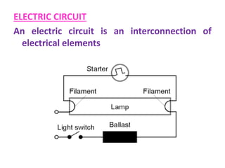
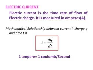
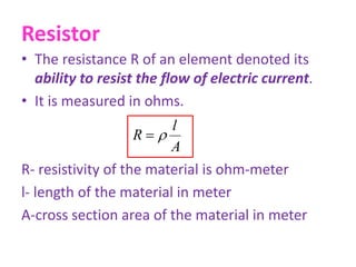
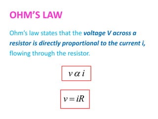
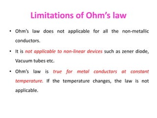
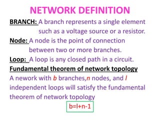
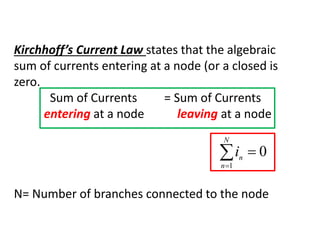
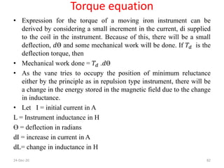
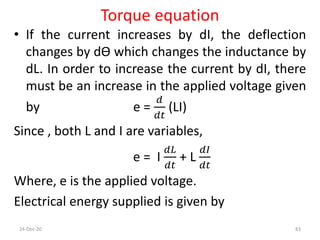
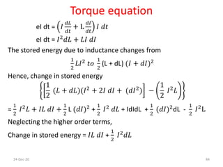
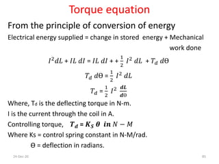
This document provides an overview of basic electrical and electronics engineering concepts including circuit components and Ohm's law. It discusses electric current, voltage, power, energy, sources, and basic circuit elements like resistors, inductors, and capacitors. Kirchhoff's laws and different circuit analysis methods like mesh current, node voltage, and source transformation are also introduced. Finally, the document covers electrical measurement techniques and types of instruments.


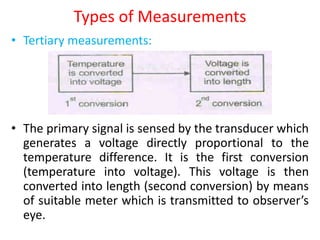


![[Deck] What's New in Spark-Iceberg Integration via DSV2.pptx](https://cdn.slidesharecdn.com/ss_thumbnails/deckwhatsnewinspark-icebergintegrationviadsv2-260210005337-25955b12-thumbnail.jpg?width=640&height=640&fit=bounds)


