Downloaded 300 times
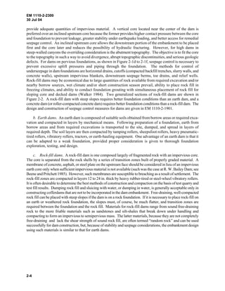

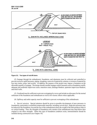


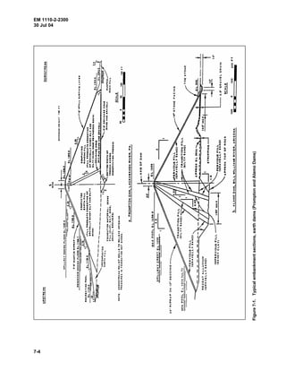
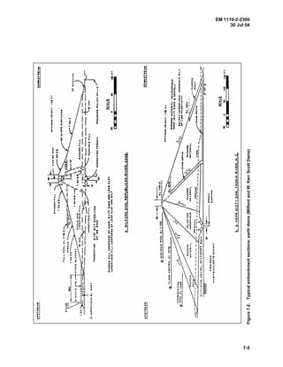
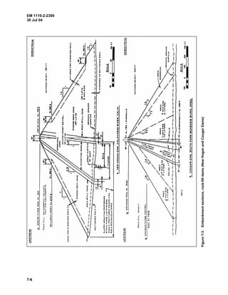
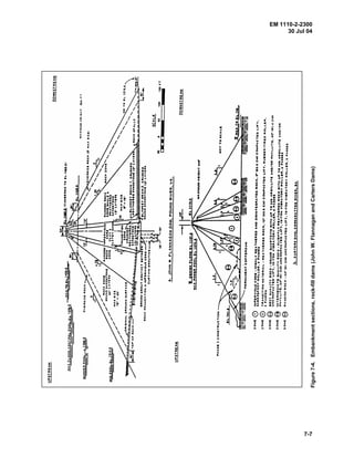


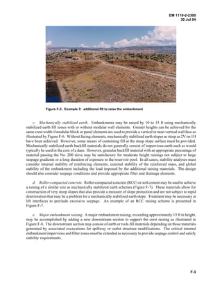


This document provides guidance on the design and construction of earth and rock-fill dams. It discusses the civil works project process from reconnaissance through construction. Key steps include detailed site investigations, evaluating alternative dam types and designs, addressing stability, seepage, and other safety requirements. Close coordination between design and construction is emphasized.


![Geotechnical Engineering-II [Lec #26: Slope Stability]](https://cdn.slidesharecdn.com/ss_thumbnails/26-181125070353-thumbnail.jpg?width=640&height=640&fit=bounds)


