Downloaded 1,747 times

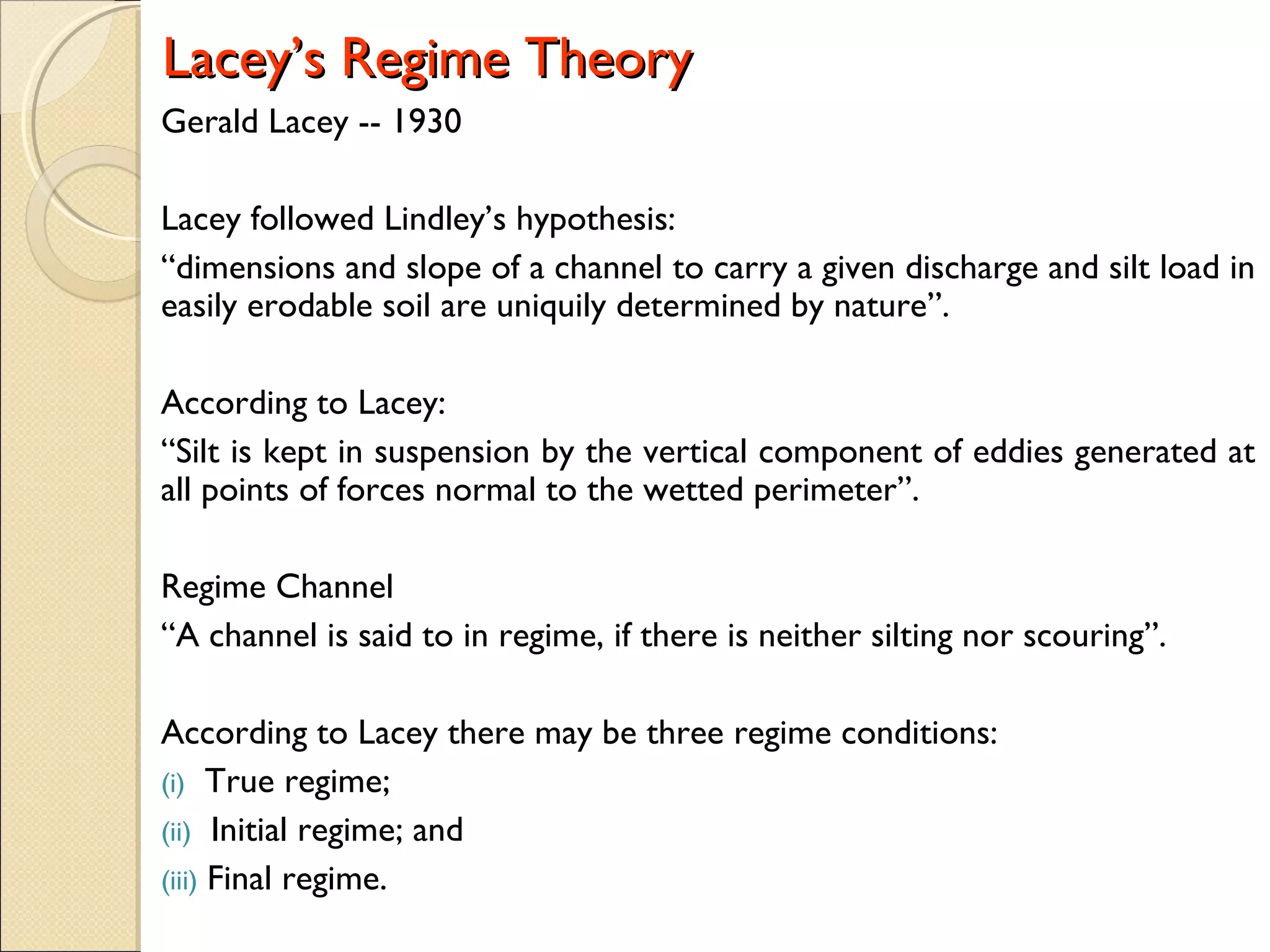
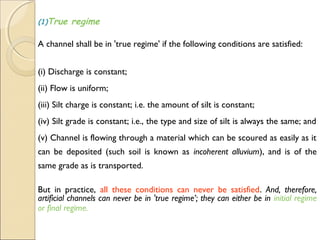
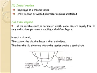

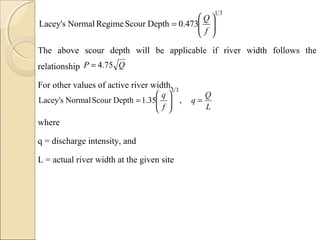
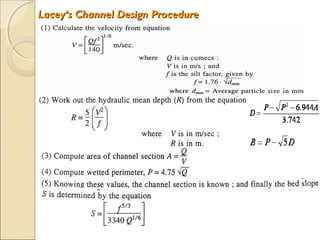

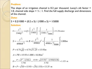
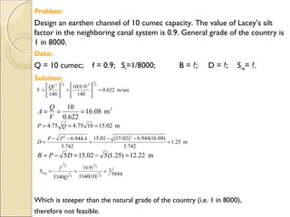
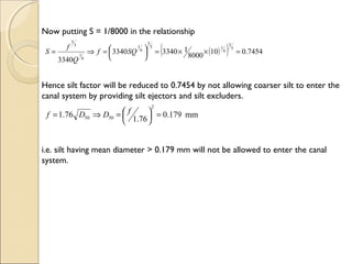
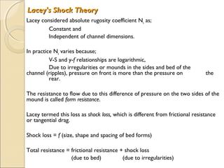
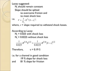
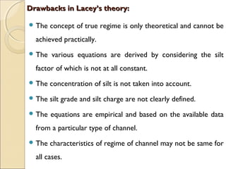
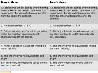

Lacey's regime theory states that the dimensions and slope of a channel are uniquely determined by the discharge, silt load, and erodibility of the soil material. A channel is in regime if there is no scouring or silting. Lacey proposed equations to calculate parameters like velocity, slope, and dimensions based on variables like discharge, silt factor, and side slopes. The theory has limitations as the conditions of true regime cannot be achieved and parameters like silt grade/load are not clearly defined. Lacey also developed shock theory accounting for form resistance due to bed irregularities.


![11. Silt Theories [Lacey's Theory].pdf](https://cdn.slidesharecdn.com/ss_thumbnails/11-230714062706-5eed0a09-thumbnail.jpg?width=640&height=640&fit=bounds)


![09. Silt Theories [Lacey's Theory].pdfhhh](https://cdn.slidesharecdn.com/ss_thumbnails/09-251204104457-d5588341-thumbnail.jpg?width=640&height=640&fit=bounds)


