Downloaded 3,148 times

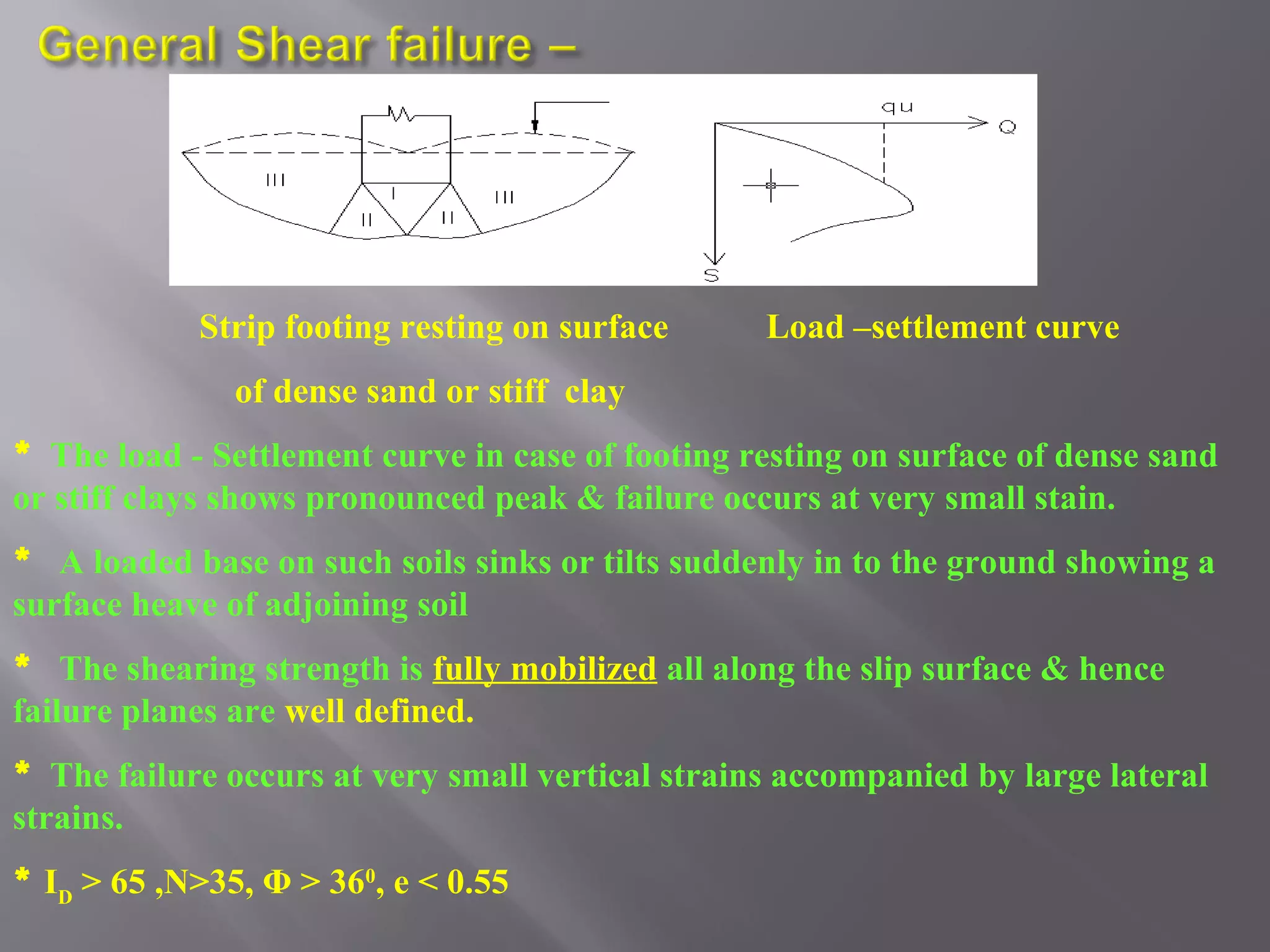
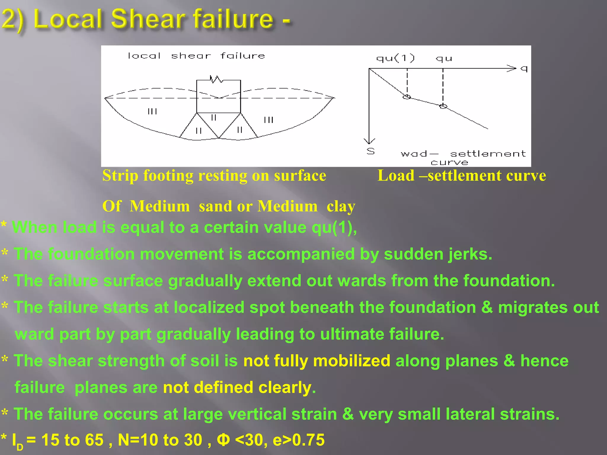
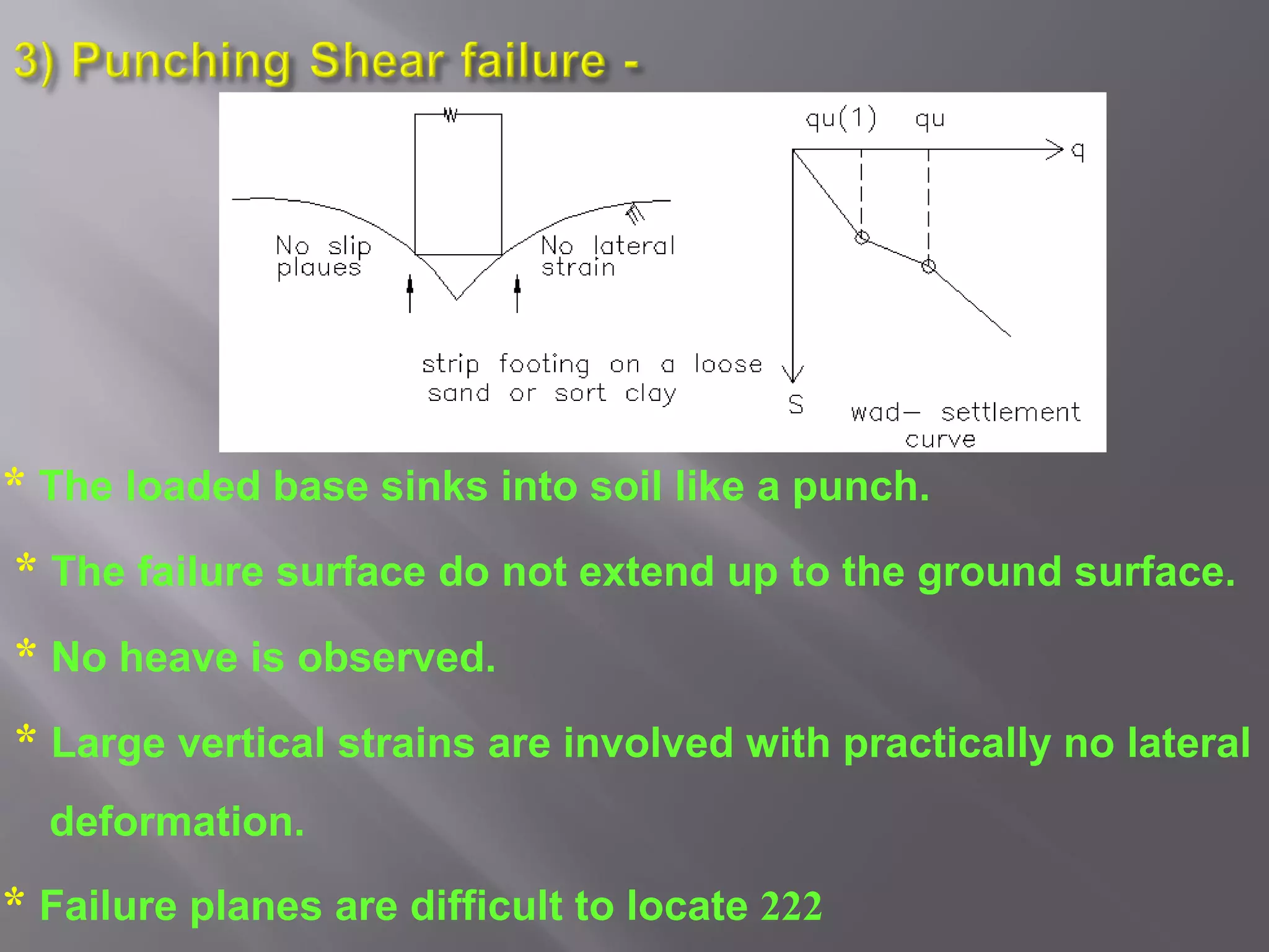
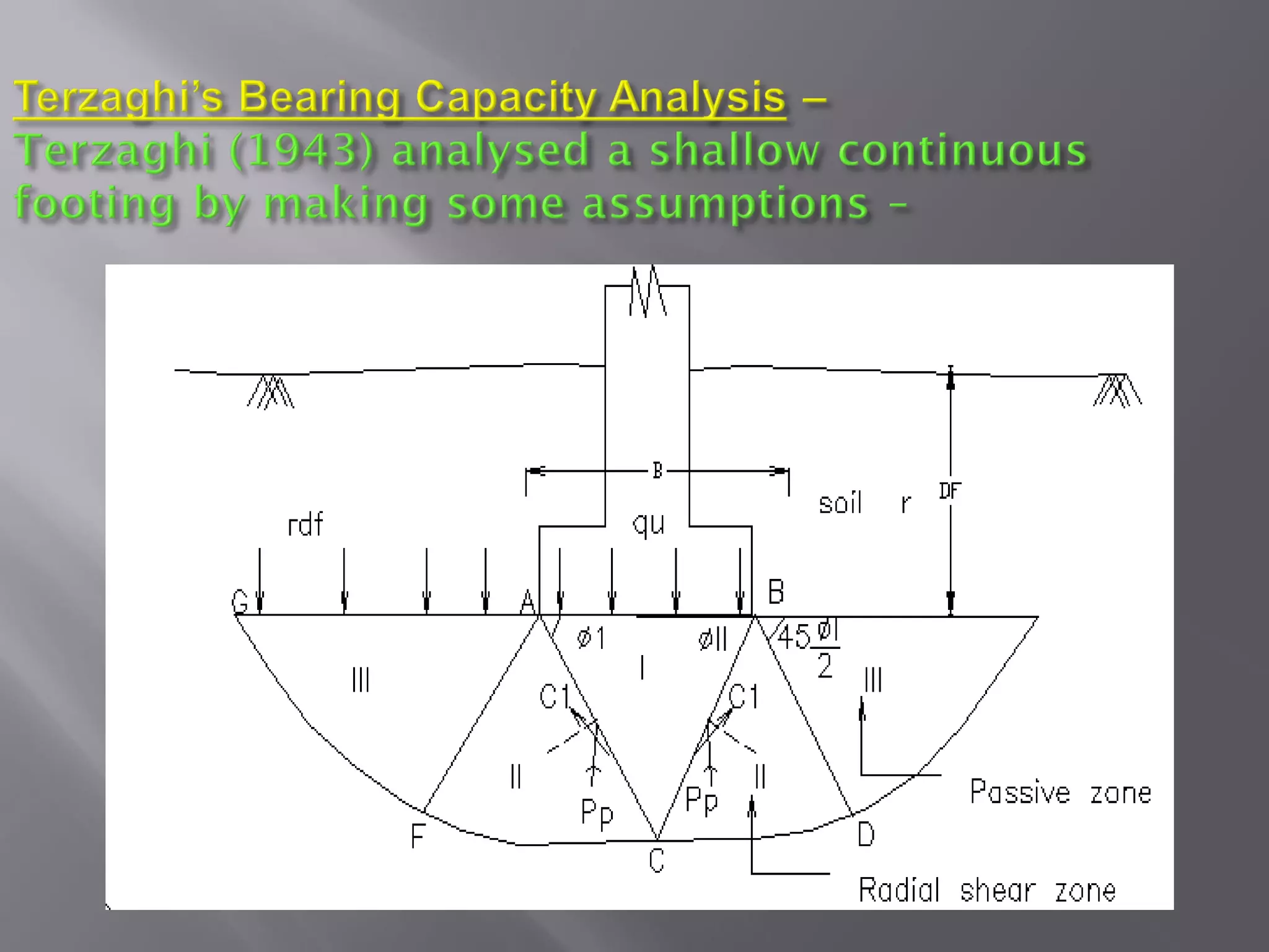


1. Load-settlement curves for footings on dense sand or stiff clay show a pronounced peak and failure occurs at very small strains, with sudden sinking or tilting and surface heaving of adjoining soil. 2. For medium sand or clay, failure starts at a localized spot and migrates outward gradually, with large vertical strains and small lateral strains. Failure planes are not clearly defined. 3. Failure zones for footings on slopes do not extend above the horizontal plane through the base, and failure occurs when downward and upward pressures are equal.


![Geotechnical Engineering-II [Lec #17: Bearing Capacity of Soil]](https://cdn.slidesharecdn.com/ss_thumbnails/17-181123045836-thumbnail.jpg?width=640&height=640&fit=bounds)


![Bearing Capacity Of Foundation (Dr Naveed Ahmad )[Autosaved]-1.pptx](https://cdn.slidesharecdn.com/ss_thumbnails/bearingcapacityoffoundationdrnaveedahmadautosaved-1-240330123634-9de86334-thumbnail.jpg?width=640&height=640&fit=bounds)


