Downloaded 751 times

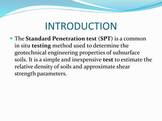


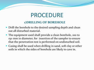
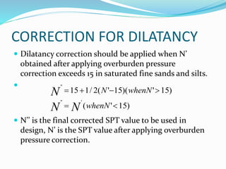
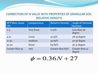
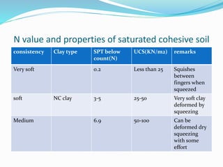
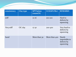
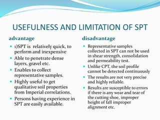


The document summarizes the standard penetration test (SPT), a common in situ geotechnical testing method. It describes the basic procedure, which involves driving a split spoon sampler into subsurface soils using a hammer, and recording the number of blows required for each increment of penetration. Corrections are made to SPT values to account for overburden pressure and dilatancy. Empirical correlations are presented relating SPT values to properties like density, shear strength, and consistency of cohesionless and cohesive soils. Both advantages like being inexpensive and quick, and limitations like lack of precision are discussed.