Download to read offline
![Heat Transfer Analysis of Advanced ic Engine Cylinder
DOI: 10.9790/1684-1303044552 www.iosrjournals.org 52 | Page
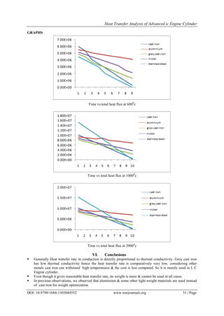
Due to the use of other light weight materials as an insulation around cast iron by reducing thickness of cast
iron we can effectively reduce the weight of cylinder and cylinder head with improved strength. Also due to
the use of air cooling system an efficient and faster cooling of engine can be achieved.
Cylinder made of different materials like stainless steel, aluminium, nickel are analyzed using
CATIAV5R20 package for modeling and same can be imported to ANSYS for analysis. Depending on the
thermal conductivity of the materials, heat transfer rate is analysed. With the advancement in material science,
very light weight materials with good thermal and mechanical properties can be used for safe desugn of the IC
engines.
References
[1] Dimitov L(2001), “Principle of mechanical engineering design”.
[2] Mcvey(1955), “material in engine design”.
[3] A text book on Machine Design, V.Bandari- TMH publishers.
[4] A text on machine design by SMD Jallaludin, Anuradha publications.
[5] Design of machine elements by pandya and shah.
[6] Timoshenko(1947),”strength of materials”.
[7] A text book on IC engines, Mathur and Sharma- dhanpath rai and sons publications.
[8] A text book on fundamentals of heat and mass transfer by RC Sachdeva, new age international publication.
[9] SAE paper on “weight reduced engine”(1992) volume 101 “journal of engine section-3”
[10] Release 11.0 documentation for ANSYS work bench, ANSYS Inc., Canorsburg PA(2007).
[11] Ravindra R. Navthar and Prashant A. Narwade, “ Design and Analysis of Cylinder and Cylinder head of 4- Stroke SI Engine For
Weight Reduction” Material Selection ,International Journal of Engineering Science and Technology, vol 4 No.03 march 2012.
[12] Shiang Woei Chyuan, “Finite element simulation of a twin-cam 16-valve cylinder Structure”, Finite Elements in Analysis and
Design 35, 2000
[13] ANSYS element reference, ANSYS 6.0 documentation, ANSYS, Inc.
[14] A. R. Bhagat, Y. M. Jibhakate, Thermal Analysis and Optimization of I.C. Engine Piston Using Finite Element Method,
International Journal of Modern Engineering Research (IJMER), Vol.2, Issue.4, pp.2919-2921, 2012](https://image.slidesharecdn.com/i1303044552-160728094407/85/I1303044552-8-320.jpg)

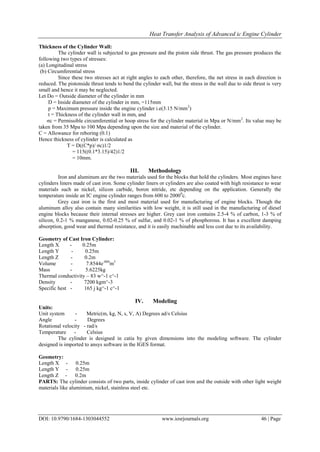
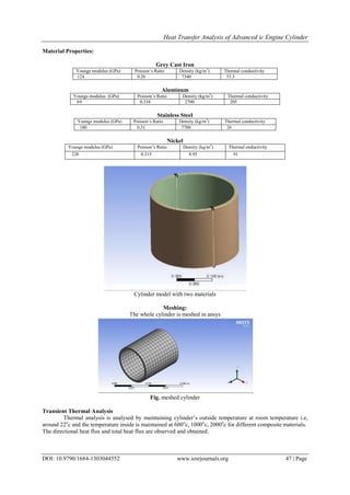
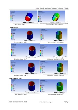
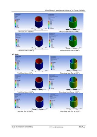
This document analyzes heat transfer in internal combustion engine cylinders made from different materials through modeling and simulation. It describes designing a cylinder with dimensions of 0.25m length, 0.25m width and 0.2m height. Materials analyzed include gray cast iron, aluminum, stainless steel, and nickel. Transient thermal analysis in ANSYS is conducted with inside cylinder temperatures of 600°C, 1000°C and 2000°C and outside at 22°C. Graphs show total and directional heat flux over time. Gray cast iron has the lowest heat transfer rate due to its low thermal conductivity but can withstand high temperatures. Aluminum and other lightweight materials are alternatives for weight optimization, though cast iron remains common due to


![[IJET V2I3-1P3] Authors:G.Siva Prasad K.Dinesh Achari E.Dileep Kumar Goud M.N...](https://cdn.slidesharecdn.com/ss_thumbnails/ijet-v2i31p3-160810100258-thumbnail.jpg?width=640&height=640&fit=bounds)


![5G Explained! A High Level Overview [Introduction]](https://cdn.slidesharecdn.com/ss_thumbnails/5gexplainedahighleveloverview-260119165306-cc137a3e-thumbnail.jpg?width=640&height=640&fit=bounds)


