Download to read offline


![Analysis and Design of Multi Cell Post-Tensioned PSC Box Girder
DOI: 10.9790/1684-12475664 www.iosrjournals.org 64 | Page
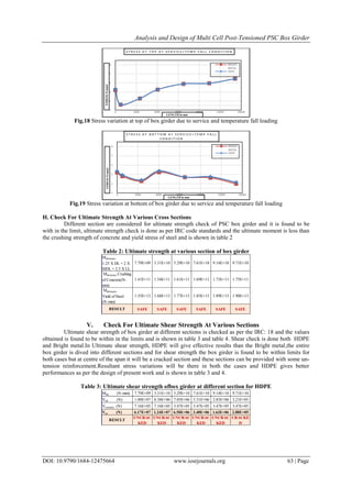
Table 4: Ultimate shear strength of box girder at different section for Bright metal
J. Check For Deflection At Midspan
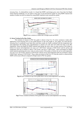
Deflection check is done for both the cases at centre of the span which is critical, the net downward defection is
32.205mm and net upward deflection due to PSC for HDPE is 24.126mm and resultant will be 8.08mm
downward which is within the limits as per IRC standards( L/500=68.5mm) and Bright metal it is about
23.378mm and resultant will be about 8.83mm downward which is within the limit of 68.55mm and it is
observed that HDPE will give less deflection than the Bright metal and hence in this case,structural stability will
be more effective.
VI. Conclusions
1. The design of PSC multi-cell box girder performed is found to be an economical design corresponding
critical bending moment and shear forces developed due to various load combinations as per IRC
specifications in comparison with the design of similar span configuration using I girders with Cast In Situ
(C.I.S) deck slab.
2. Two types of sheathing pipes have been used for cable ducts of PSC box girder modelling. The first type
being HDPE pipes whereas second type is of corrugated bright metal sheathing pipes. The results obtained
in girder with HDPE pipes are found to be more viable than corrugated bright metal pipes since the loss of
pre-stress is much less in case of HDPE pipes thereby increasing the stress levels in the concrete sections.
3. The cable profile has been determined so as to suit the bending moment diagram and cable profile adopted
in the box girder is found to be most suitable considering the kern distances of the PSC section.
4. The stresses that are developed in the box girder at service condition is found to be well within the
permissible limits as per IRC specifications and no tension being developed at any cross section in the
girder at service condition.
5. Finite Element Analysis of Box Girder from CSI Bridge modeler software is found to be more accurate and
close to reality in comparison to other analysis methods. The FEA results are in good agreement with the
results obtained from other methods.
6. It is found that the deflection obtained due to various loading conditions and at service condition is well
within permissible limits as per IRC. The maximum vertical deflection is found to occur near mid-span
location of the girder.
7. The temperature stresses that are developed due to temperature gradient as per IRC have been checked and
combined with the final stresses. The maximum final stresses are found to be in good agreement with the
allowable values.
8. The design has also been checked for Ultimate moment and Ultimate shear cases separately as per IRC
guidelines and the design is found to be safe in all respects.
References
[1]. C. Mortensen, M. Saiidi, and S. Ladkany - Creep and Shrinkage Losses in Prestressed Concrete Bridges in Highly Variable
Climates- TRB 2003 Annual Meeting CD-ROM
[2]. P. J. Barr, J. F. Stantonand M. O. Eberhard Effects of Temperature Variations on Precast Pre-stressed Concrete Bridge Girders-
journal of bridge engineering © asce / march/April 2005
[3]. Venkata Siva Reddy, P. Chandan Kumar - Response of box girder bridge spans-g. - International Journal of Bridge Engineering
(IJBE), Vol. 2, No. 2-2014
[4]. Khaled M. Sennah and John B. Kennedy - Literature Review in Analysis of Box-Girder Bridges- Journal of Bridge Engineering,
Vol. 7, No. 2, March 1- 2002.
[5]. Erin Hughs and RolaIdriss -Live-Load Distribution Factors for PrestressedConcrete,Spread Box-Girder Bridge- Journal of Bridge
Engineering, Vol. 11, No. 5, September 1-2006
[6]. Dr. Husain M. Husain and Mohanned I. Mohammed Hussein - Finite element analysis of post-tensioned concrete box girders- -
Journal of Bridge Engineering (2007)
[7]. Hiroshi Mutsuyoshi& Nguyen DucHai - Recent technology of prestressed concrete bridges in Japan- - IABSE-JSCE Joint
Conference on Advances in Bridge Engineering-II, August 8-10-2010
[8]. Ali FadhilNaser and Wang Zonglin-Finite Element and Experimental Analysis and Evaluation of Static and Dynamic Responses of
Oblique Pre-stressed Concrete Box Girder Bridge- Research Journal of Applied Sciences, Engineering and Technology 6(19):
3642-3657- 2013
[9]. T Y lin and A P burns, Design of Pre-stressed Concrete Structures, John Wiley & Sons, 3rd Edition edition,12 August 1981
[10]. N Krishna Raju, pre-stressed concrete, Tata McGraw-Hill Education, 01-Dec-2006
[11]. DR. V. K. Raina, Concrete bridges hand book, Galgotia publications, first edition, 1999
[12]. IRC:6-2000 standard specification and code of practice for road bridges
[13]. IRC:18-2000 design criteria for pre-stressed concrete road bridges
7.79E+09 3.31E+10 5.29E+10 7.61E+10 9.14E+10 9.71E+10
1.00E+07 8.38E+06 7.05E+06 5.31E+06 2.83E+06 3.21E+05
7.16E+05 7.16E+05 3.47E+05 3.47E+05 3.47E+05 3.47E+05
5.91E+07 1.20E+07 6.31E+06 3.43E+06 1.59E+06 2.83E+05
UNCRAC
KED
UNCRAC
KED
UNCRAC
KED
UNCRAC
KED
UNCRAC
KED
CRACKE
D
RESULT
Vult (N)
Vcr (N)
Vcr(min) (N)
Mult (N-mm)](https://image.slidesharecdn.com/f012475664-160711064117/85/F012475664-9-320.jpg)

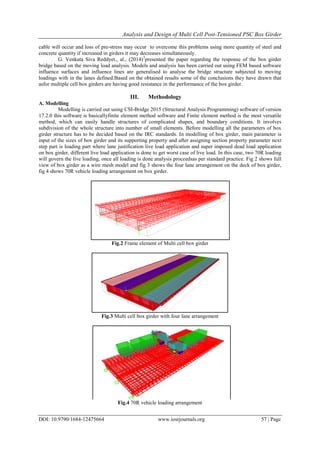
The document analyzes and designs a multi-cell post-tensioned pre-stressed concrete box girder bridge with a 35m span. Two different duct materials, HDPE and corrugated bright metal, are considered to determine the most economical design. Finite element modeling and analysis of the box girder is performed using CSI Bridge software. The design is done according to Indian code specifications, considering aspects such as section properties, load calculations, stress limits, prestressing calculations and loss estimates, and serviceability checks. Results for bending moments, shear forces, displacements and stresses are obtained and compared for both duct options.


