Downloaded 588 times

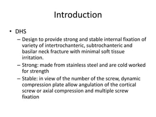

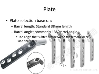
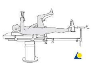

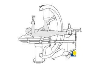

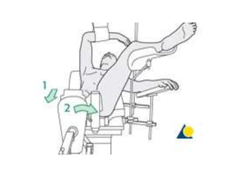
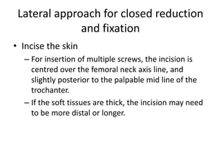
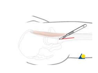
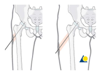

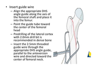
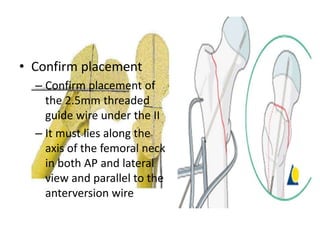


The document provides instructions for performing dynamic hip screw (DHS) surgery to treat fractures of the proximal femur. It describes: 1) Positioning the patient supine on a traction table and obtaining x-rays to visualize the hip. 2) Performing closed reduction of the fracture if possible, or open reduction if needed. 3) Making an incision over the femoral neck and inserting guide wires under fluoroscopy to align the placement of screws and plate. 4) Reaming and inserting a lag screw to stabilize the fracture followed by placement of the DHS plate and fixation screws to complete the procedure.