SlideShare a Scribd company logo
CTAN291 V1.1 Page 1 of 10 12/8/2010
Application Note
CTAN #291
The Application Note All AC Drives
A Guide to Sizing and Protecting
Dynamic Braking Resistors for AC Drives
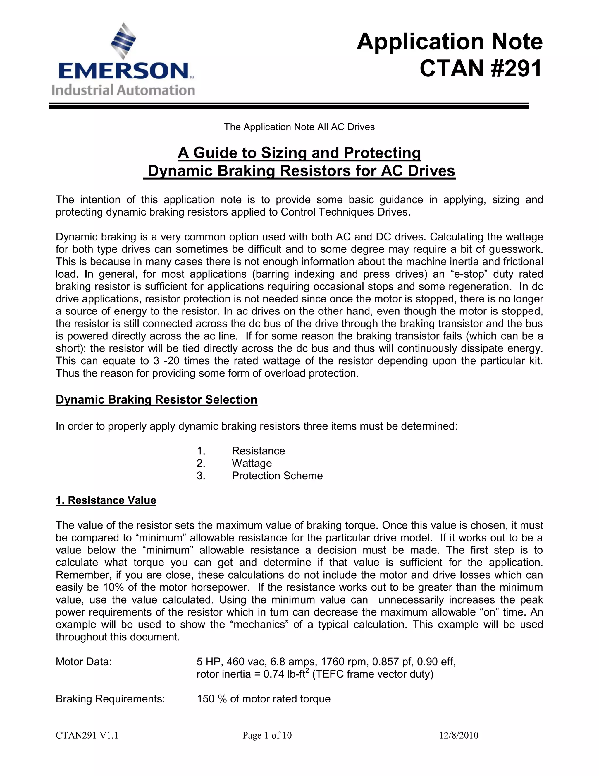
The intention of this application note is to provide some basic guidance in applying, sizing and
protecting dynamic braking resistors applied to Control Techniques Drives.
Dynamic braking is a very common option used with both AC and DC drives. Calculating the wattage
for both type drives can sometimes be difficult and to some degree may require a bit of guesswork.
This is because in many cases there is not enough information about the machine inertia and frictional
load. In general, for most applications (barring indexing and press drives) an “e-stop” duty rated
braking resistor is sufficient for applications requiring occasional stops and some regeneration. In dc
drive applications, resistor protection is not needed since once the motor is stopped, there is no longer
a source of energy to the resistor. In ac drives on the other hand, even though the motor is stopped,
the resistor is still connected across the dc bus of the drive through the braking transistor and the bus
is powered directly across the ac line. If for some reason the braking transistor fails (which can be a
short); the resistor will be tied directly across the dc bus and thus will continuously dissipate energy.
This can equate to 3 -20 times the rated wattage of the resistor depending upon the particular kit.
Thus the reason for providing some form of overload protection.
Dynamic Braking Resistor Selection
In order to properly apply dynamic braking resistors three items must be determined:
1. Resistance
2. Wattage
3. Protection Scheme
1. Resistance Value
The value of the resistor sets the maximum value of braking torque. Once this value is chosen, it must
be compared to “minimum” allowable resistance for the particular drive model. If it works out to be a
value below the “minimum” allowable resistance a decision must be made. The first step is to
calculate what torque you can get and determine if that value is sufficient for the application.
Remember, if you are close, these calculations do not include the motor and drive losses which can
easily be 10% of the motor horsepower. If the resistance works out to be greater than the minimum
value, use the value calculated. Using the minimum value can unnecessarily increases the peak
power requirements of the resistor which in turn can decrease the maximum allowable “on” time. An
example will be used to show the “mechanics” of a typical calculation. This example will be used
throughout this document.
Motor Data: 5 HP, 460 vac, 6.8 amps, 1760 rpm, 0.857 pf, 0.90 eff,
rotor inertia = 0.74 lb-ft2
(TEFC frame vector duty)
Braking Requirements: 150 % of motor rated torque
CTAN291 V1.1 Page 2 of 10 12/8/2010
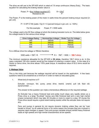
The drive we will use is the SP1405 which is rated at 7.6 amps continuous (Heavy Duty). The basic
equation for calculating the braking resistor value is:
Power, P = Bus Voltage squared (V2
) R = (Vb)2
Resistance (R) P
The Power, P is the braking power of the motor in watts times the percent braking torque required (in
per unit)
P = 5 HP X 746 (watts / Hp) X 1.5 (percent torque in per unit, i.e. 150%)
For this example: Power, P = 5595 watts
The voltage used is the DC Bus voltage at which the braking transistor turns on. The table below gives
the voltage levels for the various drive ratings
Drive Voltage Rating Nominal Bus Voltage Brake Turn On Voltage
240 340vdc 390vdc
480 680vdc 780vdc
575 813vdc 930vdc
690 976vdc 1120vdc
For a 480vac drive the voltage is 780vdc therefore:
5595 watts = 7802
/ R R = 7802
/ 5595 = 108.7 ohms
The minimum resistance allowable for the SP1405 is 58 ohms, therefore 108.7 ohms is ok. In this
case a standard 100 ohm resistor would be fine instead of ordering a custom value. In the case of a
Vector or Servo drive, the drive allows 175% peak torque. A resistance value of 93.2 ohms would be
required.
2. Wattage Value
This is the tricky part because the wattage required will be based on the application. A few basic
questions need to be answered as a minimum in order to make an educated guess.
1. What kind of machine is it?
Extruder, conveyor, fan, pump, press drive, rewind, unwind, pull roll, feed roll,
dynamometer ….
The answer to this question can make a tremendous difference on the required wattage.
An Extruder has a heavy frictional load and pretty much stops very rapidly where as a
Press drive is a large “fly-wheel” having very little frictional load and a very high inertial
(mass) component which may take 30 minutes or more to coast to a stop. Of course the
Press drive would require a good sized braking resistor while the extruder does not require
any.
Fans and pumps in general do not require dynamic braking unless they can be “over
hauled or driven” by an external force or for some reason the process they are involved in
requires rapid changes in speed. Fans and pumps (variable torque) exhibit heavy frictional
loads at high speeds and high inertial characteristics at low speeds.
CTAN291 V1.1 Page 3 of 10 12/8/2010
2. How often is the machine stopped?
Again, the size of the braking resistor can be greatly affected by frequency of stopping.
For applications requiring an occasional stop, a resistor rated at 5-10% of the drive rating is
adequate where as an indexing application, may require as much as a 50% to 75% of the
drive rating.
3. a) How long does it take the machine to coast from full speed to zero?
b) How long does it take the machine to accelerate from one speed to another speed at a
specific torque level?
c) How much motor load is there when the machine is running?
Knowing these Items help characterize the machine, i.e. frictional load and inertia.
4. Is the braking used to absorb energy during a speed change?
In this application you might want to know how often the speed is changed and what the
speed change is. This would be very similar to an indexing application.
5. Is the motor being used to provide hold back torque or to prevent the motor from being
overhauled?
This would typically be a continuous duty application where the wattage would be directly
proportional to the required “hold-back” torque.
6. What is the machine Inertia?
Knowing this allows you to calculate the stored energy of the machine and thus more easily
determine the required wattage of the brake resistor. This is commonly the case with
indexing applications.
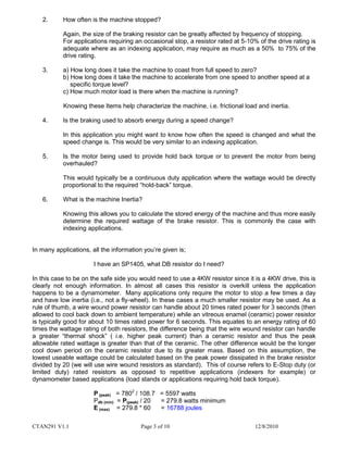
In many applications, all the information you’re given is;
I have an SP1405, what DB resistor do I need?
In this case to be on the safe side you would need to use a 4KW resistor since it is a 4KW drive, this is
clearly not enough information. In almost all cases this resistor is overkill unless the application
happens to be a dynamometer. Many applications only require the motor to stop a few times a day
and have low inertia (i.e., not a fly-wheel). In these cases a much smaller resistor may be used. As a
rule of thumb, a wire wound power resistor can handle about 20 times rated power for 3 seconds (then
allowed to cool back down to ambient temperature) while an vitreous enamel (ceramic) power resistor
is typically good for about 10 times rated power for 6 seconds. This equates to an energy rating of 60
times the wattage rating of both resistors, the difference being that the wire wound resistor can handle
a greater “thermal shock” ( i.e. higher peak current) than a ceramic resistor and thus the peak
allowable rated wattage is greater than that of the ceramic. The other difference would be the longer
cool down period on the ceramic resistor due to its greater mass. Based on this assumption, the
lowest useable wattage could be calculated based on the peak power dissipated in the brake resistor
divided by 20 (we will use wire wound resistors as standard). This of course refers to E-Stop duty (or
limited duty) rated resistors as opposed to repetitive applications (indexers for example) or
dynamometer based applications (load stands or applications requiring hold back torque).
P (peak) = 7802
/ 108.7 = 5597 watts
Pdb (min) = P(peak) / 20 = 279.8 watts minimum
E (max) = 279.8 * 60 = 16788 joules
CTAN291 V1.1 Page 4 of 10 12/8/2010
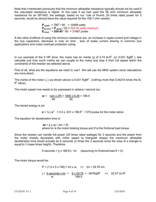
Note that I mentioned previously that the minimum allowable resistance typically should not be used if
the calculated resistance is higher. In this case if we had used the 58 ohm minimum allowable
resistance for an SP1405, the wattage, based on our “rule of thumb; 20 times rated power for 3
seconds, would be almost twice the value required for the 108.7 ohm resistor.
P (peak) = 7802
/ 58 = 10489 watts
Pdb (min) = P (peak) / 20 = 524.45 watts minimum
E (max) = 524.45 * 60 = 31467 joules
A few other ill effects of using the minimum resistance are, an increase in ripple current and voltage in
the bus capacitors, decrease in max on time , lack of brake current sharing in common bus
applications and motor overload protection sizing.
In our example of the 5 HP drive, the motor has an inertia (j) of 0.74 lb-ft2
(or 0.031 KgM2
), lets
calculate just how much inertia we can couple to the motor and stop it from full speed within the
constraints of the resistor we selected above.
First of all, what are the equations we need to use? We will use the MKS system since calculations
are more direct.
The inertia of the motor ( j ) as shown above is 0.031 KgM2
(nothing more that 0.04214 times the lb-
ft2
value).
The motor speed now needs to be expressed in radians / second (w).
w = rpm x 2Pi = 1800 x 6.28 = 188.5
60 60
The stored energy is (e):
e = ½ j w2
= 0.5 x .031 x 188.52
= 570 joules for the motor alone
The equation for deceleration time is:
td = (j x w) / (tm + tf)
where tm is the motor braking torque and tf is the frictional load torque
Since the resistor can handle full power (20 times rated wattage) for 3 seconds and the power from
the motor linearly decreases with motor speed (a triangular shape) the maximum allowable
deceleration time would actually be 6 seconds (2 times the 3 seconds since the area of a triangle is
equal to ½ base times height). Therefore:
6 seconds = (j x 188.5) / tm (assuming no frictional load tf = 0)
The motor torque would be:
P = (1.5 x 5 x 746) = tm x w, => tm = 29.76 nm
j = 6 seconds x tm = 6 x 29.76 = .947KgM2
=> 22.47 Lb-ft2
w 188.5
CTAN291 V1.1 Page 5 of 10 12/8/2010
This is equal to 30 times the motor inertia. A flywheel made of steel with a 1 inch thickness and 20
inch diameter would have about this amount of inertia compared to a motor rotor size of 6.3 inches
thick and 5 inches in diameter.
As a comparison, the motor by itself could be stopped in less than 0.2 seconds @ 150% braking
torque.
A system with this amount of inertia would take about 3 minutes to ramp down to zero speed with 5%
braking torque (frictional and drive losses) as opposed to 6 seconds when 150% braking torque is
available.
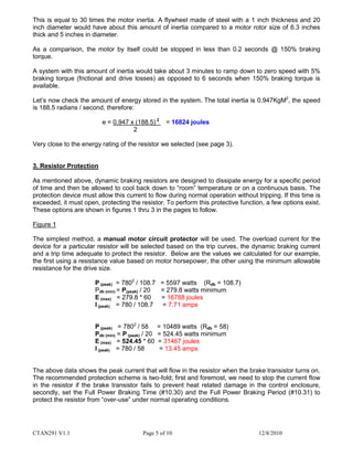
Let’s now check the amount of energy stored in the system. The total inertia is 0.947KgM2
, the speed
is 188.5 radians / second, therefore:
e = 0.947 x (188.5) 2
= 16824 joules
2
Very close to the energy rating of the resistor we selected (see page 3).
3. Resistor Protection
As mentioned above, dynamic braking resistors are designed to dissipate energy for a specific period
of time and then be allowed to cool back down to “room” temperature or on a continuous basis. The
protection device must allow this current to flow during normal operation without tripping. If this time is
exceeded, it must open, protecting the resistor. To perform this protective function, a few options exist.
These options are shown in figures 1 thru 3 in the pages to follow.
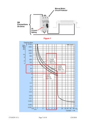
Figure 1
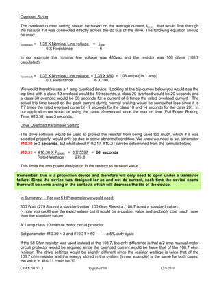
The simplest method, a manual motor circuit protector will be used. The overload current for the
device for a particular resistor will be selected based on the trip curves, the dynamic braking current
and a trip time adequate to protect the resistor. Below are the values we calculated for our example,
the first using a resistance value based on motor horsepower, the other using the minimum allowable
resistance for the drive size.
P (peak) = 7802
/ 108.7 = 5597 watts (Rdb = 108.7)
Pdb (min) = P(peak) / 20 = 279.8 watts minimum
E (max) = 279.8 * 60 = 16788 joules
I (peak) = 780 / 108.7 = 7.71 amps
P (peak) = 7802
/ 58 = 10489 watts (Rdb = 58)
Pdb (min) = P (peak) / 20 = 524.45 watts minimum
E (max) = 524.45 * 60 = 31467 joules
I (peak) = 780 / 58 = 13.45 amps
The above data shows the peak current that will flow in the resistor when the brake transistor turns on.
The recommended protection scheme is two-fold; first and foremost, we need to stop the current flow
in the resistor if the brake transistor fails to prevent heat related damage in the control enclosure,
secondly, set the Full Power Braking Time (#10.30) and the Full Power Braking Period (#10.31) to
protect the resistor from “over-use” under normal operating conditions.
CTAN291 V1.1 Page 6 of 10 12/8/2010
Overload Sizing
The overload current setting should be based on the average current, I(ave) , that would flow through
the resistor if it was connected directly across the dc bus of the drive. The following equation should
be used:
I(overload) = 1.35 X Nominal Line voltage = I(ave)
6 X Resistance 6
In our example the nominal line voltage was 480vac and the resistor was 100 ohms (108.7
calculated).
I(overload) = 1.35 X Nominal Line voltage = 1.35 X 480 = 1.08 amps ( ie 1 amp)
6 X Resistance 6 X 100
We would therefore use a 1 amp overload device. Looking at the trip curves below you would see the
trip time with a class 10 overload would be 10 seconds, a class 20 overload would be 20 seconds and
a class 30 overload would be 30 seconds for a current of 6 times the rated overload current. The
actual trip time based on the peak current during normal braking would be somewhat less since it is
7.7 times the rated overload current (~ 7 seconds for the class 10 and 14 seconds for the class 20). In
our application we would be using the class 10 overload since the max on time (Full Power Braking
Time, #10.30) was 3 seconds.
Drive Overload Parameter Setting
The drive software would be used to protect the resistor from being used too much, which if it was
selected properly, would only be due to some abnormal condition. We know we need to set parameter
#10.30 to 3 seconds, but what about #10.31? #10.31 can be determined from the formula below;
#10.31 = #10.30 X P(peak) = 3 X 5597 = 60 seconds
Rated Wattage 279.8
This limits the rms power dissipation in the resistor to its rated value.
In Summary: For our 5 HP example we would need:
300 Watt (279.8 is not a standard value) 100 Ohm Resistor (108.7 is not a standard value)
(- note you could use the exact values but it would be a custom value and probably cost much more
than the standard value)
A 1 amp class 10 manual motor circuit protector
Set parameter #10.30 = 3 and #10.31 = 60 --- a 5% duty cycle
If the 58 Ohm resistor was used instead of the 108.7, the only difference is that a 2 amp manual motor
circuit protector would be required since the overload current would be twice that of the 108.7 ohm
resistor. The drive settings would be slightly different since the resistor wattage is twice that of the
108.7 ohm resistor and the energy stored in the system (in our example) is the same for both cases,
the value in #10.31 could be 30.
Remember, this is a protection device and therefore will only need to open under a transistor
failure. Since the device was designed for ac and not dc current, each time the device opens
there will be some arcing in the contacts which will decrease the life of the device.
CTAN291 V1.1 Page 7 of 10 12/8/2010
DB
Connections
On Drive
Manual Motor
Circuit Protector
Figure 1
OL
Current
Setting
CTAN291 V1.1 Page 8 of 10 12/8/2010
DB
Connections
On Drive
Motor
Thermal
Overload
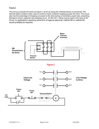
Figure 2
Figure 2
This set up is exactly the same as Figure 1 as far as sizing the overload device is concerned. The
thermal switch contact is then used to control a motor contactor supplying power the drive. This circuit
also has the advantage of dropping out power to the drive during a momentary power loss; preventing
damage to drive’s capacitor pre-charging circuit. An IEC AC-1 rating may be used in the input of AC
Drives. In applications requiring some form of agency approval, method #2 or method #3
would probably be required.
Thermal
Switch
Input Line
Voltage
L1
L2
L3
1L1
1L2
1L3
Line Voltage
to Drive
Power
ON
C
C
115
VAC
Thermal Switch
Power
Off
CTAN291 V1.1 Page 9 of 10 12/8/2010
DB
Connections
On Drive
Thermal
Switch
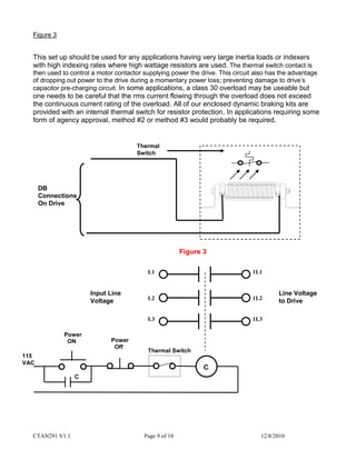
Figure 3
Figure 3
This set up should be used for any applications having very large inertia loads or indexers
with high indexing rates where high wattage resistors are used. The thermal switch contact is
then used to control a motor contactor supplying power the drive. This circuit also has the advantage
of dropping out power to the drive during a momentary power loss; preventing damage to drive’s
capacitor pre-charging circuit. In some applications, a class 30 overload may be useable but
one needs to be careful that the rms current flowing through the overload does not exceed
the continuous current rating of the overload. All of our enclosed dynamic braking kits are
provided with an internal thermal switch for resistor protection. In applications requiring some
form of agency approval, method #2 or method #3 would probably be required.
Input Line
Voltage
L1
L2
L3
1L1
1L2
1L3
Line Voltage
to Drive
C
C
115
VAC
Thermal Switch
Power
Off
Power
ON
CTAN291 V1.1 Page 10 of 10 12/8/2010
4. Overload / Braking Resistor Wiring Guide
In order to determine the appropriate wire size to connect a dynamic braking resistor to an AC
Drive, you need to know the resistance value and voltage class of the drive. The resistance can
either be measured with a digital multi-meter or if it was obtained from Control Techniques, the
part number of the kit contains the resistance value.
DBR-0100-03000-enc This would be a 10 Ohm , 3000 Watt resistor
DBR-XXX.X (ohms) – XXXXX (watts)- enc (enclosed unit)
The current through the resistor can then be calculated based on the resistance value and the
“Nominal Bus Voltage” in the table below.
For a 480vac drive with the 10 Ohm resistor, the current would be 680/10 = 68 amps. The wire
gauge would be based on this current, the maximum ambient temperature whether the wires
are run in “free air” or conduit. This info can be found in the National Electrical Code handbook
and or Local electrical codes.
Drive Voltage Rating Nominal Bus Voltage Brake Turn On Voltage
240 340vdc 390vdc
480 680vdc 780vdc
575 813vdc 930vdc
690 976vdc 1120vdc
When referring to wiring within the resistor enclosure (not exiting the enclosure) the following
applies (note that this wire is still useable to wire to the drive as well, its advantage is the
smaller gauge size) ;
Internal wiring connecting to heating circuits shall have a temperature rating of 200°C per
UL508A 2005 Edition, 26.4.4.
Wire Gage / Current Rating* HP @ 240 VAC HP @ 480 VAC
14 awg / 54 1 - 15 1 - 30
12 awg / 68 20 - 60 40 - 125
10 awg / 90 75 150
Table based on highest HP in column and the drives minimum allowable resistance
Based on single conductor in free air
Questions: Ask the author??
Steve Zaleski Email: mailto:steve.zaleski@emerson.com Tel: 800-367-8067

More Related Content

What's hot

star delta auto starter with forward reverse and motor protection
star delta auto starter with forward reverse and motor protectionstar delta auto starter with forward reverse and motor protection
star delta auto starter with forward reverse and motor protection
BHUPATI PRADHAN
 
Transformer maintenance
Transformer maintenance Transformer maintenance
Transformer maintenance
Molla Morshad
 
Power transformer protection
Power transformer protectionPower transformer protection
Power transformer protection
michaeljmack
 
Presentation on Power transformer
Presentation on Power transformerPresentation on Power transformer
Presentation on Power transformer
Sudarshan Pandey
 
srm
srmsrm
ABB ACS 800 SERIES VFD TRAINNING GUIDE BY DEEPAK GORAI
ABB ACS 800 SERIES VFD TRAINNING GUIDE BY DEEPAK GORAIABB ACS 800 SERIES VFD TRAINNING GUIDE BY DEEPAK GORAI
ABB ACS 800 SERIES VFD TRAINNING GUIDE BY DEEPAK GORAI
DEEPAK GORAI
 
Motor starter
Motor starterMotor starter
Motor starter
BHAGWAN PRASAD
 
Maintenance schedule of Substation.
Maintenance schedule of Substation.Maintenance schedule of Substation.
Maintenance schedule of Substation.
Sheikh Nazmul Islam
 
Relay coordination
Relay coordinationRelay coordination
Relay coordination
D Målîk
 
Automatic voltaer regulator and it's modelling
Automatic voltaer regulator and it's modellingAutomatic voltaer regulator and it's modelling
Automatic voltaer regulator and it's modelling
rajani51
 
Energy Savings with Variable Frequency Drives
Energy Savings with Variable Frequency DrivesEnergy Savings with Variable Frequency Drives
Energy Savings with Variable Frequency Drives
Azizah Kassim
 
Protection & switchgear
Protection & switchgear   Protection & switchgear
Protection & switchgear
johny renoald
 
Tap Changer
Tap ChangerTap Changer
Tap Changer
Pankaj Singh
 
RTCC & AVR
RTCC & AVRRTCC & AVR
RTCC & AVR
Indiran K
 
MCC PANEL WIRING, GA and BOM Sample
MCC PANEL WIRING, GA and BOM SampleMCC PANEL WIRING, GA and BOM Sample
MCC PANEL WIRING, GA and BOM Sample
Shashi Kant
 
Operation and maintenance of transformer
Operation and maintenance of transformerOperation and maintenance of transformer
Operation and maintenance of transformer
Kapil Singh
 
Presentation on starter
Presentation on starterPresentation on starter
Presentation on starter
aftab alam
 
Safe Operation and Maintenance of Circuit Breakers and Switchgear
Safe Operation and Maintenance of Circuit Breakers and SwitchgearSafe Operation and Maintenance of Circuit Breakers and Switchgear
Safe Operation and Maintenance of Circuit Breakers and Switchgear
Living Online
 
Energy efficient motors
Energy efficient motorsEnergy efficient motors
Energy efficient motors
Jagadeesh Madhura
 
Moulded Case Circuit Breaker (Mccb) & air circuit breaker (acb)
Moulded Case Circuit Breaker (Mccb) & air circuit breaker (acb)Moulded Case Circuit Breaker (Mccb) & air circuit breaker (acb)
Moulded Case Circuit Breaker (Mccb) & air circuit breaker (acb)
Hazem El-Henawy
 

What's hot (20)

star delta auto starter with forward reverse and motor protection
star delta auto starter with forward reverse and motor protectionstar delta auto starter with forward reverse and motor protection
star delta auto starter with forward reverse and motor protection
 
Transformer maintenance
Transformer maintenance Transformer maintenance
Transformer maintenance
 
Power transformer protection
Power transformer protectionPower transformer protection
Power transformer protection
 
Presentation on Power transformer
Presentation on Power transformerPresentation on Power transformer
Presentation on Power transformer
 
srm
srmsrm
srm
 
ABB ACS 800 SERIES VFD TRAINNING GUIDE BY DEEPAK GORAI
ABB ACS 800 SERIES VFD TRAINNING GUIDE BY DEEPAK GORAIABB ACS 800 SERIES VFD TRAINNING GUIDE BY DEEPAK GORAI
ABB ACS 800 SERIES VFD TRAINNING GUIDE BY DEEPAK GORAI
 
Motor starter
Motor starterMotor starter
Motor starter
 
Maintenance schedule of Substation.
Maintenance schedule of Substation.Maintenance schedule of Substation.
Maintenance schedule of Substation.
 
Relay coordination
Relay coordinationRelay coordination
Relay coordination
 
Automatic voltaer regulator and it's modelling
Automatic voltaer regulator and it's modellingAutomatic voltaer regulator and it's modelling
Automatic voltaer regulator and it's modelling
 
Energy Savings with Variable Frequency Drives
Energy Savings with Variable Frequency DrivesEnergy Savings with Variable Frequency Drives
Energy Savings with Variable Frequency Drives
 
Protection & switchgear
Protection & switchgear   Protection & switchgear
Protection & switchgear
 
Tap Changer
Tap ChangerTap Changer
Tap Changer
 
RTCC & AVR
RTCC & AVRRTCC & AVR
RTCC & AVR
 
MCC PANEL WIRING, GA and BOM Sample
MCC PANEL WIRING, GA and BOM SampleMCC PANEL WIRING, GA and BOM Sample
MCC PANEL WIRING, GA and BOM Sample
 
Operation and maintenance of transformer
Operation and maintenance of transformerOperation and maintenance of transformer
Operation and maintenance of transformer
 
Presentation on starter
Presentation on starterPresentation on starter
Presentation on starter
 
Safe Operation and Maintenance of Circuit Breakers and Switchgear
Safe Operation and Maintenance of Circuit Breakers and SwitchgearSafe Operation and Maintenance of Circuit Breakers and Switchgear
Safe Operation and Maintenance of Circuit Breakers and Switchgear
 
Energy efficient motors
Energy efficient motorsEnergy efficient motors
Energy efficient motors
 
Moulded Case Circuit Breaker (Mccb) & air circuit breaker (acb)
Moulded Case Circuit Breaker (Mccb) & air circuit breaker (acb)Moulded Case Circuit Breaker (Mccb) & air circuit breaker (acb)
Moulded Case Circuit Breaker (Mccb) & air circuit breaker (acb)
 

Similar to dynamic braking resistor selection calculation

SURVEY OF CONVENTIONAL &NEW GENERATION ADVANCED D.C.BRAKING SYSTEM OF 3-PHASE...
SURVEY OF CONVENTIONAL &NEW GENERATION ADVANCED D.C.BRAKING SYSTEM OF 3-PHASE...SURVEY OF CONVENTIONAL &NEW GENERATION ADVANCED D.C.BRAKING SYSTEM OF 3-PHASE...
SURVEY OF CONVENTIONAL &NEW GENERATION ADVANCED D.C.BRAKING SYSTEM OF 3-PHASE...
IJCI JOURNAL
 
Variable Frequency Drives and Energy Savings: It‘s More Than Just Fan and Pum...
Variable Frequency Drives and Energy Savings: It‘s More Than Just Fan and Pum...Variable Frequency Drives and Energy Savings: It‘s More Than Just Fan and Pum...
Variable Frequency Drives and Energy Savings: It‘s More Than Just Fan and Pum...
Instrument Specialties, Inc.
 
Vfd drive motor load
Vfd drive motor loadVfd drive motor load
Vfd drive motor load
Zhaoyi Fang
 
Major faults in an alternator and their protection.
Major faults in an alternator and their protection.Major faults in an alternator and their protection.
Major faults in an alternator and their protection.
javid iqbal sodagar
 
4.5 assessment of motors n
4.5 assessment of  motors n4.5 assessment of  motors n
4.5 assessment of motors n
priya3757
 
Abb technical guide no.08 revb
Abb technical guide no.08 revbAbb technical guide no.08 revb
Abb technical guide no.08 revb
Cesar Enrique Gutierrez Candia
 
chapter 7.pdf
chapter 7.pdfchapter 7.pdf
chapter 7.pdf
SushantPoudel11
 
three phase induction motor drive
three phase induction motor drivethree phase induction motor drive
three phase induction motor drive
Ratnesh Verma
 
Nidec asi electric power solutions for pipeline applications
Nidec asi electric power solutions for pipeline applicationsNidec asi electric power solutions for pipeline applications
Nidec asi electric power solutions for pipeline applications
Nidec Corporation
 
IRJET- Adaptive Observer-Based Fault Estimation for DFIG based Wind Turbine S...
IRJET- Adaptive Observer-Based Fault Estimation for DFIG based Wind Turbine S...IRJET- Adaptive Observer-Based Fault Estimation for DFIG based Wind Turbine S...
IRJET- Adaptive Observer-Based Fault Estimation for DFIG based Wind Turbine S...
IRJET Journal
 
Braking of Three Phase Induction Motorsby Controlling Applied Voltage and Fre...
Braking of Three Phase Induction Motorsby Controlling Applied Voltage and Fre...Braking of Three Phase Induction Motorsby Controlling Applied Voltage and Fre...
Braking of Three Phase Induction Motorsby Controlling Applied Voltage and Fre...
IJPEDS-IAES
 
Vsd3
Vsd3Vsd3
Switched Reluctance Motor Initial Design for Electric Vehicle using RMxprt
Switched Reluctance Motor Initial Design for Electric Vehicle using RMxprtSwitched Reluctance Motor Initial Design for Electric Vehicle using RMxprt
Switched Reluctance Motor Initial Design for Electric Vehicle using RMxprt
International Journal of Power Electronics and Drive Systems
 
Thor power, technical summary, 1210
Thor power, technical summary, 1210Thor power, technical summary, 1210
Thor power, technical summary, 1210
Thor Power Corporation
 
Elspec equalizer st-the_ultimate_motor_start-up_solution_datasheet
Elspec equalizer st-the_ultimate_motor_start-up_solution_datasheetElspec equalizer st-the_ultimate_motor_start-up_solution_datasheet
Elspec equalizer st-the_ultimate_motor_start-up_solution_datasheet
Angus Sankaran
 
Kada003 ac drives_diagnostics_report
Kada003 ac drives_diagnostics_reportKada003 ac drives_diagnostics_report
Kada003 ac drives_diagnostics_report
brumaller
 
PMSM.pdf
PMSM.pdfPMSM.pdf
Single phase-induction-motor(eee499.blogspot.com)
Single phase-induction-motor(eee499.blogspot.com)Single phase-induction-motor(eee499.blogspot.com)
Single phase-induction-motor(eee499.blogspot.com)
slmnsvn
 
powerfactor.pdf
powerfactor.pdfpowerfactor.pdf
powerfactor.pdf
Saravanan A
 
Power Factor.ppt
Power Factor.pptPower Factor.ppt
Power Factor.ppt
Vidya Sagar
 

Similar to dynamic braking resistor selection calculation (20)

SURVEY OF CONVENTIONAL &NEW GENERATION ADVANCED D.C.BRAKING SYSTEM OF 3-PHASE...
SURVEY OF CONVENTIONAL &NEW GENERATION ADVANCED D.C.BRAKING SYSTEM OF 3-PHASE...SURVEY OF CONVENTIONAL &NEW GENERATION ADVANCED D.C.BRAKING SYSTEM OF 3-PHASE...
SURVEY OF CONVENTIONAL &NEW GENERATION ADVANCED D.C.BRAKING SYSTEM OF 3-PHASE...
 
Variable Frequency Drives and Energy Savings: It‘s More Than Just Fan and Pum...
Variable Frequency Drives and Energy Savings: It‘s More Than Just Fan and Pum...Variable Frequency Drives and Energy Savings: It‘s More Than Just Fan and Pum...
Variable Frequency Drives and Energy Savings: It‘s More Than Just Fan and Pum...
 
Vfd drive motor load
Vfd drive motor loadVfd drive motor load
Vfd drive motor load
 
Major faults in an alternator and their protection.
Major faults in an alternator and their protection.Major faults in an alternator and their protection.
Major faults in an alternator and their protection.
 
4.5 assessment of motors n
4.5 assessment of  motors n4.5 assessment of  motors n
4.5 assessment of motors n
 
Abb technical guide no.08 revb
Abb technical guide no.08 revbAbb technical guide no.08 revb
Abb technical guide no.08 revb
 
chapter 7.pdf
chapter 7.pdfchapter 7.pdf
chapter 7.pdf
 
three phase induction motor drive
three phase induction motor drivethree phase induction motor drive
three phase induction motor drive
 
Nidec asi electric power solutions for pipeline applications
Nidec asi electric power solutions for pipeline applicationsNidec asi electric power solutions for pipeline applications
Nidec asi electric power solutions for pipeline applications
 
IRJET- Adaptive Observer-Based Fault Estimation for DFIG based Wind Turbine S...
IRJET- Adaptive Observer-Based Fault Estimation for DFIG based Wind Turbine S...IRJET- Adaptive Observer-Based Fault Estimation for DFIG based Wind Turbine S...
IRJET- Adaptive Observer-Based Fault Estimation for DFIG based Wind Turbine S...
 
Braking of Three Phase Induction Motorsby Controlling Applied Voltage and Fre...
Braking of Three Phase Induction Motorsby Controlling Applied Voltage and Fre...Braking of Three Phase Induction Motorsby Controlling Applied Voltage and Fre...
Braking of Three Phase Induction Motorsby Controlling Applied Voltage and Fre...
 
Vsd3
Vsd3Vsd3
Vsd3
 
Switched Reluctance Motor Initial Design for Electric Vehicle using RMxprt
Switched Reluctance Motor Initial Design for Electric Vehicle using RMxprtSwitched Reluctance Motor Initial Design for Electric Vehicle using RMxprt
Switched Reluctance Motor Initial Design for Electric Vehicle using RMxprt
 
Thor power, technical summary, 1210
Thor power, technical summary, 1210Thor power, technical summary, 1210
Thor power, technical summary, 1210
 
Elspec equalizer st-the_ultimate_motor_start-up_solution_datasheet
Elspec equalizer st-the_ultimate_motor_start-up_solution_datasheetElspec equalizer st-the_ultimate_motor_start-up_solution_datasheet
Elspec equalizer st-the_ultimate_motor_start-up_solution_datasheet
 
Kada003 ac drives_diagnostics_report
Kada003 ac drives_diagnostics_reportKada003 ac drives_diagnostics_report
Kada003 ac drives_diagnostics_report
 
PMSM.pdf
PMSM.pdfPMSM.pdf
PMSM.pdf
 
Single phase-induction-motor(eee499.blogspot.com)
Single phase-induction-motor(eee499.blogspot.com)Single phase-induction-motor(eee499.blogspot.com)
Single phase-induction-motor(eee499.blogspot.com)
 
powerfactor.pdf
powerfactor.pdfpowerfactor.pdf
powerfactor.pdf
 
Power Factor.ppt
Power Factor.pptPower Factor.ppt
Power Factor.ppt
 

Recently uploaded

Low power architecture of logic gates using adiabatic techniques
Low power architecture of logic gates using adiabatic techniquesLow power architecture of logic gates using adiabatic techniques
Low power architecture of logic gates using adiabatic techniques
nooriasukmaningtyas
 
Properties Railway Sleepers and Test.pptx
Properties Railway Sleepers and Test.pptxProperties Railway Sleepers and Test.pptx
Properties Railway Sleepers and Test.pptx
MDSABBIROJJAMANPAYEL
 
DEEP LEARNING FOR SMART GRID INTRUSION DETECTION: A HYBRID CNN-LSTM-BASED MODEL
DEEP LEARNING FOR SMART GRID INTRUSION DETECTION: A HYBRID CNN-LSTM-BASED MODELDEEP LEARNING FOR SMART GRID INTRUSION DETECTION: A HYBRID CNN-LSTM-BASED MODEL
DEEP LEARNING FOR SMART GRID INTRUSION DETECTION: A HYBRID CNN-LSTM-BASED MODEL
gerogepatton
 
Manufacturing Process of molasses based distillery ppt.pptx
Manufacturing Process of molasses based distillery ppt.pptxManufacturing Process of molasses based distillery ppt.pptx
Manufacturing Process of molasses based distillery ppt.pptx
Madan Karki
 
A SYSTEMATIC RISK ASSESSMENT APPROACH FOR SECURING THE SMART IRRIGATION SYSTEMS
A SYSTEMATIC RISK ASSESSMENT APPROACH FOR SECURING THE SMART IRRIGATION SYSTEMSA SYSTEMATIC RISK ASSESSMENT APPROACH FOR SECURING THE SMART IRRIGATION SYSTEMS
A SYSTEMATIC RISK ASSESSMENT APPROACH FOR SECURING THE SMART IRRIGATION SYSTEMS
IJNSA Journal
 
spirit beverages ppt without graphics.pptx
spirit beverages ppt without graphics.pptxspirit beverages ppt without graphics.pptx
spirit beverages ppt without graphics.pptx
Madan Karki
 
[JPP-1] - (JEE 3.0) - Kinematics 1D - 14th May..pdf
[JPP-1] - (JEE 3.0) - Kinematics 1D - 14th May..pdf[JPP-1] - (JEE 3.0) - Kinematics 1D - 14th May..pdf
[JPP-1] - (JEE 3.0) - Kinematics 1D - 14th May..pdf
awadeshbabu
 
14 Template Contractual Notice - EOT Application
14 Template Contractual Notice - EOT Application14 Template Contractual Notice - EOT Application
14 Template Contractual Notice - EOT Application
SyedAbiiAzazi1
 
Iron and Steel Technology Roadmap - Towards more sustainable steelmaking.pdf
Iron and Steel Technology Roadmap - Towards more sustainable steelmaking.pdfIron and Steel Technology Roadmap - Towards more sustainable steelmaking.pdf
Iron and Steel Technology Roadmap - Towards more sustainable steelmaking.pdf
RadiNasr
 
Modelagem de um CSTR com reação endotermica.pdf
Modelagem de um CSTR com reação endotermica.pdfModelagem de um CSTR com reação endotermica.pdf
Modelagem de um CSTR com reação endotermica.pdf
camseq
 
ACEP Magazine edition 4th launched on 05.06.2024
ACEP Magazine edition 4th launched on 05.06.2024ACEP Magazine edition 4th launched on 05.06.2024
ACEP Magazine edition 4th launched on 05.06.2024
Rahul
 
6th International Conference on Machine Learning & Applications (CMLA 2024)
6th International Conference on Machine Learning & Applications (CMLA 2024)6th International Conference on Machine Learning & Applications (CMLA 2024)
6th International Conference on Machine Learning & Applications (CMLA 2024)
ClaraZara1
 
DfMAy 2024 - key insights and contributions
DfMAy 2024 - key insights and contributionsDfMAy 2024 - key insights and contributions
DfMAy 2024 - key insights and contributions
gestioneergodomus
 
Electric vehicle and photovoltaic advanced roles in enhancing the financial p...
Electric vehicle and photovoltaic advanced roles in enhancing the financial p...Electric vehicle and photovoltaic advanced roles in enhancing the financial p...
Electric vehicle and photovoltaic advanced roles in enhancing the financial p...
IJECEIAES
 
IEEE Aerospace and Electronic Systems Society as a Graduate Student Member
IEEE Aerospace and Electronic Systems Society as a Graduate Student MemberIEEE Aerospace and Electronic Systems Society as a Graduate Student Member
IEEE Aerospace and Electronic Systems Society as a Graduate Student Member
VICTOR MAESTRE RAMIREZ
 
Technical Drawings introduction to drawing of prisms
Technical Drawings introduction to drawing of prismsTechnical Drawings introduction to drawing of prisms
Technical Drawings introduction to drawing of prisms
heavyhaig
 
Swimming pool mechanical components design.pptx
Swimming pool  mechanical components design.pptxSwimming pool  mechanical components design.pptx
Swimming pool mechanical components design.pptx
yokeleetan1
 
New techniques for characterising damage in rock slopes.pdf
New techniques for characterising damage in rock slopes.pdfNew techniques for characterising damage in rock slopes.pdf
New techniques for characterising damage in rock slopes.pdf
wisnuprabawa3
 
Presentation of IEEE Slovenia CIS (Computational Intelligence Society) Chapte...
Presentation of IEEE Slovenia CIS (Computational Intelligence Society) Chapte...Presentation of IEEE Slovenia CIS (Computational Intelligence Society) Chapte...
Presentation of IEEE Slovenia CIS (Computational Intelligence Society) Chapte...
University of Maribor
 
KuberTENes Birthday Bash Guadalajara - K8sGPT first impressions
KuberTENes Birthday Bash Guadalajara - K8sGPT first impressionsKuberTENes Birthday Bash Guadalajara - K8sGPT first impressions
KuberTENes Birthday Bash Guadalajara - K8sGPT first impressions
Victor Morales
 

Recently uploaded (20)

Low power architecture of logic gates using adiabatic techniques
Low power architecture of logic gates using adiabatic techniquesLow power architecture of logic gates using adiabatic techniques
Low power architecture of logic gates using adiabatic techniques
 
Properties Railway Sleepers and Test.pptx
Properties Railway Sleepers and Test.pptxProperties Railway Sleepers and Test.pptx
Properties Railway Sleepers and Test.pptx
 
DEEP LEARNING FOR SMART GRID INTRUSION DETECTION: A HYBRID CNN-LSTM-BASED MODEL
DEEP LEARNING FOR SMART GRID INTRUSION DETECTION: A HYBRID CNN-LSTM-BASED MODELDEEP LEARNING FOR SMART GRID INTRUSION DETECTION: A HYBRID CNN-LSTM-BASED MODEL
DEEP LEARNING FOR SMART GRID INTRUSION DETECTION: A HYBRID CNN-LSTM-BASED MODEL
 
Manufacturing Process of molasses based distillery ppt.pptx
Manufacturing Process of molasses based distillery ppt.pptxManufacturing Process of molasses based distillery ppt.pptx
Manufacturing Process of molasses based distillery ppt.pptx
 
A SYSTEMATIC RISK ASSESSMENT APPROACH FOR SECURING THE SMART IRRIGATION SYSTEMS
A SYSTEMATIC RISK ASSESSMENT APPROACH FOR SECURING THE SMART IRRIGATION SYSTEMSA SYSTEMATIC RISK ASSESSMENT APPROACH FOR SECURING THE SMART IRRIGATION SYSTEMS
A SYSTEMATIC RISK ASSESSMENT APPROACH FOR SECURING THE SMART IRRIGATION SYSTEMS
 
spirit beverages ppt without graphics.pptx
spirit beverages ppt without graphics.pptxspirit beverages ppt without graphics.pptx
spirit beverages ppt without graphics.pptx
 
[JPP-1] - (JEE 3.0) - Kinematics 1D - 14th May..pdf
[JPP-1] - (JEE 3.0) - Kinematics 1D - 14th May..pdf[JPP-1] - (JEE 3.0) - Kinematics 1D - 14th May..pdf
[JPP-1] - (JEE 3.0) - Kinematics 1D - 14th May..pdf
 
14 Template Contractual Notice - EOT Application
14 Template Contractual Notice - EOT Application14 Template Contractual Notice - EOT Application
14 Template Contractual Notice - EOT Application
 
Iron and Steel Technology Roadmap - Towards more sustainable steelmaking.pdf
Iron and Steel Technology Roadmap - Towards more sustainable steelmaking.pdfIron and Steel Technology Roadmap - Towards more sustainable steelmaking.pdf
Iron and Steel Technology Roadmap - Towards more sustainable steelmaking.pdf
 
Modelagem de um CSTR com reação endotermica.pdf
Modelagem de um CSTR com reação endotermica.pdfModelagem de um CSTR com reação endotermica.pdf
Modelagem de um CSTR com reação endotermica.pdf
 
ACEP Magazine edition 4th launched on 05.06.2024
ACEP Magazine edition 4th launched on 05.06.2024ACEP Magazine edition 4th launched on 05.06.2024
ACEP Magazine edition 4th launched on 05.06.2024
 
6th International Conference on Machine Learning & Applications (CMLA 2024)
6th International Conference on Machine Learning & Applications (CMLA 2024)6th International Conference on Machine Learning & Applications (CMLA 2024)
6th International Conference on Machine Learning & Applications (CMLA 2024)
 
DfMAy 2024 - key insights and contributions
DfMAy 2024 - key insights and contributionsDfMAy 2024 - key insights and contributions
DfMAy 2024 - key insights and contributions
 
Electric vehicle and photovoltaic advanced roles in enhancing the financial p...
Electric vehicle and photovoltaic advanced roles in enhancing the financial p...Electric vehicle and photovoltaic advanced roles in enhancing the financial p...
Electric vehicle and photovoltaic advanced roles in enhancing the financial p...
 
IEEE Aerospace and Electronic Systems Society as a Graduate Student Member
IEEE Aerospace and Electronic Systems Society as a Graduate Student MemberIEEE Aerospace and Electronic Systems Society as a Graduate Student Member
IEEE Aerospace and Electronic Systems Society as a Graduate Student Member
 
Technical Drawings introduction to drawing of prisms
Technical Drawings introduction to drawing of prismsTechnical Drawings introduction to drawing of prisms
Technical Drawings introduction to drawing of prisms
 
Swimming pool mechanical components design.pptx
Swimming pool  mechanical components design.pptxSwimming pool  mechanical components design.pptx
Swimming pool mechanical components design.pptx
 
New techniques for characterising damage in rock slopes.pdf
New techniques for characterising damage in rock slopes.pdfNew techniques for characterising damage in rock slopes.pdf
New techniques for characterising damage in rock slopes.pdf
 
Presentation of IEEE Slovenia CIS (Computational Intelligence Society) Chapte...
Presentation of IEEE Slovenia CIS (Computational Intelligence Society) Chapte...Presentation of IEEE Slovenia CIS (Computational Intelligence Society) Chapte...
Presentation of IEEE Slovenia CIS (Computational Intelligence Society) Chapte...
 
KuberTENes Birthday Bash Guadalajara - K8sGPT first impressions
KuberTENes Birthday Bash Guadalajara - K8sGPT first impressionsKuberTENes Birthday Bash Guadalajara - K8sGPT first impressions
KuberTENes Birthday Bash Guadalajara - K8sGPT first impressions
 

dynamic braking resistor selection calculation

  • 1. CTAN291 V1.1 Page 1 of 10 12/8/2010 Application Note CTAN #291 The Application Note All AC Drives A Guide to Sizing and Protecting Dynamic Braking Resistors for AC Drives The intention of this application note is to provide some basic guidance in applying, sizing and protecting dynamic braking resistors applied to Control Techniques Drives. Dynamic braking is a very common option used with both AC and DC drives. Calculating the wattage for both type drives can sometimes be difficult and to some degree may require a bit of guesswork. This is because in many cases there is not enough information about the machine inertia and frictional load. In general, for most applications (barring indexing and press drives) an “e-stop” duty rated braking resistor is sufficient for applications requiring occasional stops and some regeneration. In dc drive applications, resistor protection is not needed since once the motor is stopped, there is no longer a source of energy to the resistor. In ac drives on the other hand, even though the motor is stopped, the resistor is still connected across the dc bus of the drive through the braking transistor and the bus is powered directly across the ac line. If for some reason the braking transistor fails (which can be a short); the resistor will be tied directly across the dc bus and thus will continuously dissipate energy. This can equate to 3 -20 times the rated wattage of the resistor depending upon the particular kit. Thus the reason for providing some form of overload protection. Dynamic Braking Resistor Selection In order to properly apply dynamic braking resistors three items must be determined: 1. Resistance 2. Wattage 3. Protection Scheme 1. Resistance Value The value of the resistor sets the maximum value of braking torque. Once this value is chosen, it must be compared to “minimum” allowable resistance for the particular drive model. If it works out to be a value below the “minimum” allowable resistance a decision must be made. The first step is to calculate what torque you can get and determine if that value is sufficient for the application. Remember, if you are close, these calculations do not include the motor and drive losses which can easily be 10% of the motor horsepower. If the resistance works out to be greater than the minimum value, use the value calculated. Using the minimum value can unnecessarily increases the peak power requirements of the resistor which in turn can decrease the maximum allowable “on” time. An example will be used to show the “mechanics” of a typical calculation. This example will be used throughout this document. Motor Data: 5 HP, 460 vac, 6.8 amps, 1760 rpm, 0.857 pf, 0.90 eff, rotor inertia = 0.74 lb-ft2 (TEFC frame vector duty) Braking Requirements: 150 % of motor rated torque
  • 2. CTAN291 V1.1 Page 2 of 10 12/8/2010 The drive we will use is the SP1405 which is rated at 7.6 amps continuous (Heavy Duty). The basic equation for calculating the braking resistor value is: Power, P = Bus Voltage squared (V2 ) R = (Vb)2 Resistance (R) P The Power, P is the braking power of the motor in watts times the percent braking torque required (in per unit) P = 5 HP X 746 (watts / Hp) X 1.5 (percent torque in per unit, i.e. 150%) For this example: Power, P = 5595 watts The voltage used is the DC Bus voltage at which the braking transistor turns on. The table below gives the voltage levels for the various drive ratings Drive Voltage Rating Nominal Bus Voltage Brake Turn On Voltage 240 340vdc 390vdc 480 680vdc 780vdc 575 813vdc 930vdc 690 976vdc 1120vdc For a 480vac drive the voltage is 780vdc therefore: 5595 watts = 7802 / R R = 7802 / 5595 = 108.7 ohms The minimum resistance allowable for the SP1405 is 58 ohms, therefore 108.7 ohms is ok. In this case a standard 100 ohm resistor would be fine instead of ordering a custom value. In the case of a Vector or Servo drive, the drive allows 175% peak torque. A resistance value of 93.2 ohms would be required. 2. Wattage Value This is the tricky part because the wattage required will be based on the application. A few basic questions need to be answered as a minimum in order to make an educated guess. 1. What kind of machine is it? Extruder, conveyor, fan, pump, press drive, rewind, unwind, pull roll, feed roll, dynamometer …. The answer to this question can make a tremendous difference on the required wattage. An Extruder has a heavy frictional load and pretty much stops very rapidly where as a Press drive is a large “fly-wheel” having very little frictional load and a very high inertial (mass) component which may take 30 minutes or more to coast to a stop. Of course the Press drive would require a good sized braking resistor while the extruder does not require any. Fans and pumps in general do not require dynamic braking unless they can be “over hauled or driven” by an external force or for some reason the process they are involved in requires rapid changes in speed. Fans and pumps (variable torque) exhibit heavy frictional loads at high speeds and high inertial characteristics at low speeds.
  • 3. CTAN291 V1.1 Page 3 of 10 12/8/2010 2. How often is the machine stopped? Again, the size of the braking resistor can be greatly affected by frequency of stopping. For applications requiring an occasional stop, a resistor rated at 5-10% of the drive rating is adequate where as an indexing application, may require as much as a 50% to 75% of the drive rating. 3. a) How long does it take the machine to coast from full speed to zero? b) How long does it take the machine to accelerate from one speed to another speed at a specific torque level? c) How much motor load is there when the machine is running? Knowing these Items help characterize the machine, i.e. frictional load and inertia. 4. Is the braking used to absorb energy during a speed change? In this application you might want to know how often the speed is changed and what the speed change is. This would be very similar to an indexing application. 5. Is the motor being used to provide hold back torque or to prevent the motor from being overhauled? This would typically be a continuous duty application where the wattage would be directly proportional to the required “hold-back” torque. 6. What is the machine Inertia? Knowing this allows you to calculate the stored energy of the machine and thus more easily determine the required wattage of the brake resistor. This is commonly the case with indexing applications. In many applications, all the information you’re given is; I have an SP1405, what DB resistor do I need? In this case to be on the safe side you would need to use a 4KW resistor since it is a 4KW drive, this is clearly not enough information. In almost all cases this resistor is overkill unless the application happens to be a dynamometer. Many applications only require the motor to stop a few times a day and have low inertia (i.e., not a fly-wheel). In these cases a much smaller resistor may be used. As a rule of thumb, a wire wound power resistor can handle about 20 times rated power for 3 seconds (then allowed to cool back down to ambient temperature) while an vitreous enamel (ceramic) power resistor is typically good for about 10 times rated power for 6 seconds. This equates to an energy rating of 60 times the wattage rating of both resistors, the difference being that the wire wound resistor can handle a greater “thermal shock” ( i.e. higher peak current) than a ceramic resistor and thus the peak allowable rated wattage is greater than that of the ceramic. The other difference would be the longer cool down period on the ceramic resistor due to its greater mass. Based on this assumption, the lowest useable wattage could be calculated based on the peak power dissipated in the brake resistor divided by 20 (we will use wire wound resistors as standard). This of course refers to E-Stop duty (or limited duty) rated resistors as opposed to repetitive applications (indexers for example) or dynamometer based applications (load stands or applications requiring hold back torque). P (peak) = 7802 / 108.7 = 5597 watts Pdb (min) = P(peak) / 20 = 279.8 watts minimum E (max) = 279.8 * 60 = 16788 joules
  • 4. CTAN291 V1.1 Page 4 of 10 12/8/2010 Note that I mentioned previously that the minimum allowable resistance typically should not be used if the calculated resistance is higher. In this case if we had used the 58 ohm minimum allowable resistance for an SP1405, the wattage, based on our “rule of thumb; 20 times rated power for 3 seconds, would be almost twice the value required for the 108.7 ohm resistor. P (peak) = 7802 / 58 = 10489 watts Pdb (min) = P (peak) / 20 = 524.45 watts minimum E (max) = 524.45 * 60 = 31467 joules A few other ill effects of using the minimum resistance are, an increase in ripple current and voltage in the bus capacitors, decrease in max on time , lack of brake current sharing in common bus applications and motor overload protection sizing. In our example of the 5 HP drive, the motor has an inertia (j) of 0.74 lb-ft2 (or 0.031 KgM2 ), lets calculate just how much inertia we can couple to the motor and stop it from full speed within the constraints of the resistor we selected above. First of all, what are the equations we need to use? We will use the MKS system since calculations are more direct. The inertia of the motor ( j ) as shown above is 0.031 KgM2 (nothing more that 0.04214 times the lb- ft2 value). The motor speed now needs to be expressed in radians / second (w). w = rpm x 2Pi = 1800 x 6.28 = 188.5 60 60 The stored energy is (e): e = ½ j w2 = 0.5 x .031 x 188.52 = 570 joules for the motor alone The equation for deceleration time is: td = (j x w) / (tm + tf) where tm is the motor braking torque and tf is the frictional load torque Since the resistor can handle full power (20 times rated wattage) for 3 seconds and the power from the motor linearly decreases with motor speed (a triangular shape) the maximum allowable deceleration time would actually be 6 seconds (2 times the 3 seconds since the area of a triangle is equal to ½ base times height). Therefore: 6 seconds = (j x 188.5) / tm (assuming no frictional load tf = 0) The motor torque would be: P = (1.5 x 5 x 746) = tm x w, => tm = 29.76 nm j = 6 seconds x tm = 6 x 29.76 = .947KgM2 => 22.47 Lb-ft2 w 188.5
  • 5. CTAN291 V1.1 Page 5 of 10 12/8/2010 This is equal to 30 times the motor inertia. A flywheel made of steel with a 1 inch thickness and 20 inch diameter would have about this amount of inertia compared to a motor rotor size of 6.3 inches thick and 5 inches in diameter. As a comparison, the motor by itself could be stopped in less than 0.2 seconds @ 150% braking torque. A system with this amount of inertia would take about 3 minutes to ramp down to zero speed with 5% braking torque (frictional and drive losses) as opposed to 6 seconds when 150% braking torque is available. Let’s now check the amount of energy stored in the system. The total inertia is 0.947KgM2 , the speed is 188.5 radians / second, therefore: e = 0.947 x (188.5) 2 = 16824 joules 2 Very close to the energy rating of the resistor we selected (see page 3). 3. Resistor Protection As mentioned above, dynamic braking resistors are designed to dissipate energy for a specific period of time and then be allowed to cool back down to “room” temperature or on a continuous basis. The protection device must allow this current to flow during normal operation without tripping. If this time is exceeded, it must open, protecting the resistor. To perform this protective function, a few options exist. These options are shown in figures 1 thru 3 in the pages to follow. Figure 1 The simplest method, a manual motor circuit protector will be used. The overload current for the device for a particular resistor will be selected based on the trip curves, the dynamic braking current and a trip time adequate to protect the resistor. Below are the values we calculated for our example, the first using a resistance value based on motor horsepower, the other using the minimum allowable resistance for the drive size. P (peak) = 7802 / 108.7 = 5597 watts (Rdb = 108.7) Pdb (min) = P(peak) / 20 = 279.8 watts minimum E (max) = 279.8 * 60 = 16788 joules I (peak) = 780 / 108.7 = 7.71 amps P (peak) = 7802 / 58 = 10489 watts (Rdb = 58) Pdb (min) = P (peak) / 20 = 524.45 watts minimum E (max) = 524.45 * 60 = 31467 joules I (peak) = 780 / 58 = 13.45 amps The above data shows the peak current that will flow in the resistor when the brake transistor turns on. The recommended protection scheme is two-fold; first and foremost, we need to stop the current flow in the resistor if the brake transistor fails to prevent heat related damage in the control enclosure, secondly, set the Full Power Braking Time (#10.30) and the Full Power Braking Period (#10.31) to protect the resistor from “over-use” under normal operating conditions.
  • 6. CTAN291 V1.1 Page 6 of 10 12/8/2010 Overload Sizing The overload current setting should be based on the average current, I(ave) , that would flow through the resistor if it was connected directly across the dc bus of the drive. The following equation should be used: I(overload) = 1.35 X Nominal Line voltage = I(ave) 6 X Resistance 6 In our example the nominal line voltage was 480vac and the resistor was 100 ohms (108.7 calculated). I(overload) = 1.35 X Nominal Line voltage = 1.35 X 480 = 1.08 amps ( ie 1 amp) 6 X Resistance 6 X 100 We would therefore use a 1 amp overload device. Looking at the trip curves below you would see the trip time with a class 10 overload would be 10 seconds, a class 20 overload would be 20 seconds and a class 30 overload would be 30 seconds for a current of 6 times the rated overload current. The actual trip time based on the peak current during normal braking would be somewhat less since it is 7.7 times the rated overload current (~ 7 seconds for the class 10 and 14 seconds for the class 20). In our application we would be using the class 10 overload since the max on time (Full Power Braking Time, #10.30) was 3 seconds. Drive Overload Parameter Setting The drive software would be used to protect the resistor from being used too much, which if it was selected properly, would only be due to some abnormal condition. We know we need to set parameter #10.30 to 3 seconds, but what about #10.31? #10.31 can be determined from the formula below; #10.31 = #10.30 X P(peak) = 3 X 5597 = 60 seconds Rated Wattage 279.8 This limits the rms power dissipation in the resistor to its rated value. In Summary: For our 5 HP example we would need: 300 Watt (279.8 is not a standard value) 100 Ohm Resistor (108.7 is not a standard value) (- note you could use the exact values but it would be a custom value and probably cost much more than the standard value) A 1 amp class 10 manual motor circuit protector Set parameter #10.30 = 3 and #10.31 = 60 --- a 5% duty cycle If the 58 Ohm resistor was used instead of the 108.7, the only difference is that a 2 amp manual motor circuit protector would be required since the overload current would be twice that of the 108.7 ohm resistor. The drive settings would be slightly different since the resistor wattage is twice that of the 108.7 ohm resistor and the energy stored in the system (in our example) is the same for both cases, the value in #10.31 could be 30. Remember, this is a protection device and therefore will only need to open under a transistor failure. Since the device was designed for ac and not dc current, each time the device opens there will be some arcing in the contacts which will decrease the life of the device.
  • 7. CTAN291 V1.1 Page 7 of 10 12/8/2010 DB Connections On Drive Manual Motor Circuit Protector Figure 1 OL Current Setting
  • 8. CTAN291 V1.1 Page 8 of 10 12/8/2010 DB Connections On Drive Motor Thermal Overload Figure 2 Figure 2 This set up is exactly the same as Figure 1 as far as sizing the overload device is concerned. The thermal switch contact is then used to control a motor contactor supplying power the drive. This circuit also has the advantage of dropping out power to the drive during a momentary power loss; preventing damage to drive’s capacitor pre-charging circuit. An IEC AC-1 rating may be used in the input of AC Drives. In applications requiring some form of agency approval, method #2 or method #3 would probably be required. Thermal Switch Input Line Voltage L1 L2 L3 1L1 1L2 1L3 Line Voltage to Drive Power ON C C 115 VAC Thermal Switch Power Off
  • 9. CTAN291 V1.1 Page 9 of 10 12/8/2010 DB Connections On Drive Thermal Switch Figure 3 Figure 3 This set up should be used for any applications having very large inertia loads or indexers with high indexing rates where high wattage resistors are used. The thermal switch contact is then used to control a motor contactor supplying power the drive. This circuit also has the advantage of dropping out power to the drive during a momentary power loss; preventing damage to drive’s capacitor pre-charging circuit. In some applications, a class 30 overload may be useable but one needs to be careful that the rms current flowing through the overload does not exceed the continuous current rating of the overload. All of our enclosed dynamic braking kits are provided with an internal thermal switch for resistor protection. In applications requiring some form of agency approval, method #2 or method #3 would probably be required. Input Line Voltage L1 L2 L3 1L1 1L2 1L3 Line Voltage to Drive C C 115 VAC Thermal Switch Power Off Power ON
  • 10. CTAN291 V1.1 Page 10 of 10 12/8/2010 4. Overload / Braking Resistor Wiring Guide In order to determine the appropriate wire size to connect a dynamic braking resistor to an AC Drive, you need to know the resistance value and voltage class of the drive. The resistance can either be measured with a digital multi-meter or if it was obtained from Control Techniques, the part number of the kit contains the resistance value. DBR-0100-03000-enc This would be a 10 Ohm , 3000 Watt resistor DBR-XXX.X (ohms) – XXXXX (watts)- enc (enclosed unit) The current through the resistor can then be calculated based on the resistance value and the “Nominal Bus Voltage” in the table below. For a 480vac drive with the 10 Ohm resistor, the current would be 680/10 = 68 amps. The wire gauge would be based on this current, the maximum ambient temperature whether the wires are run in “free air” or conduit. This info can be found in the National Electrical Code handbook and or Local electrical codes. Drive Voltage Rating Nominal Bus Voltage Brake Turn On Voltage 240 340vdc 390vdc 480 680vdc 780vdc 575 813vdc 930vdc 690 976vdc 1120vdc When referring to wiring within the resistor enclosure (not exiting the enclosure) the following applies (note that this wire is still useable to wire to the drive as well, its advantage is the smaller gauge size) ; Internal wiring connecting to heating circuits shall have a temperature rating of 200°C per UL508A 2005 Edition, 26.4.4. Wire Gage / Current Rating* HP @ 240 VAC HP @ 480 VAC 14 awg / 54 1 - 15 1 - 30 12 awg / 68 20 - 60 40 - 125 10 awg / 90 75 150 Table based on highest HP in column and the drives minimum allowable resistance Based on single conductor in free air Questions: Ask the author?? Steve Zaleski Email: mailto:steve.zaleski@emerson.com Tel: 800-367-8067