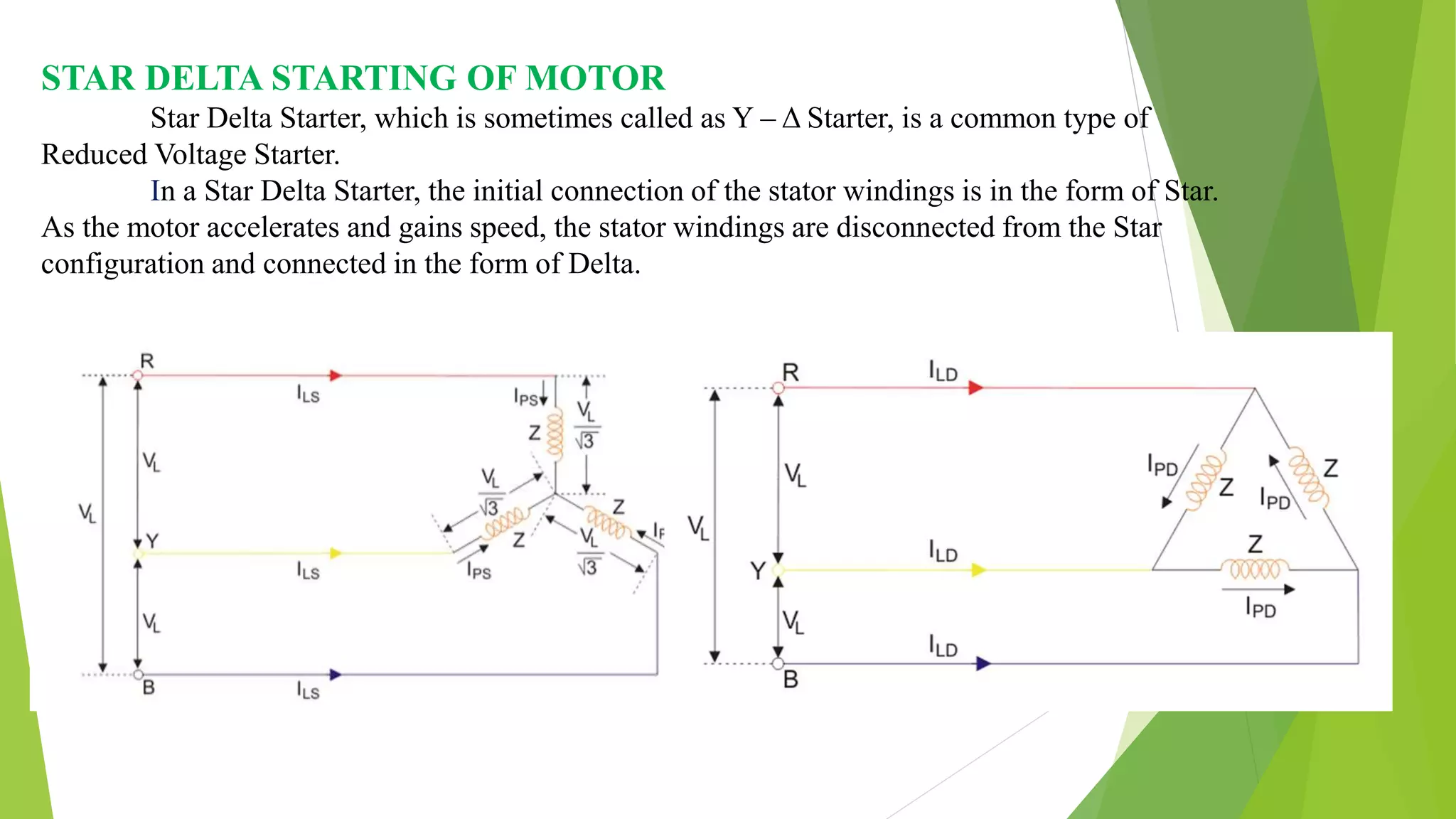
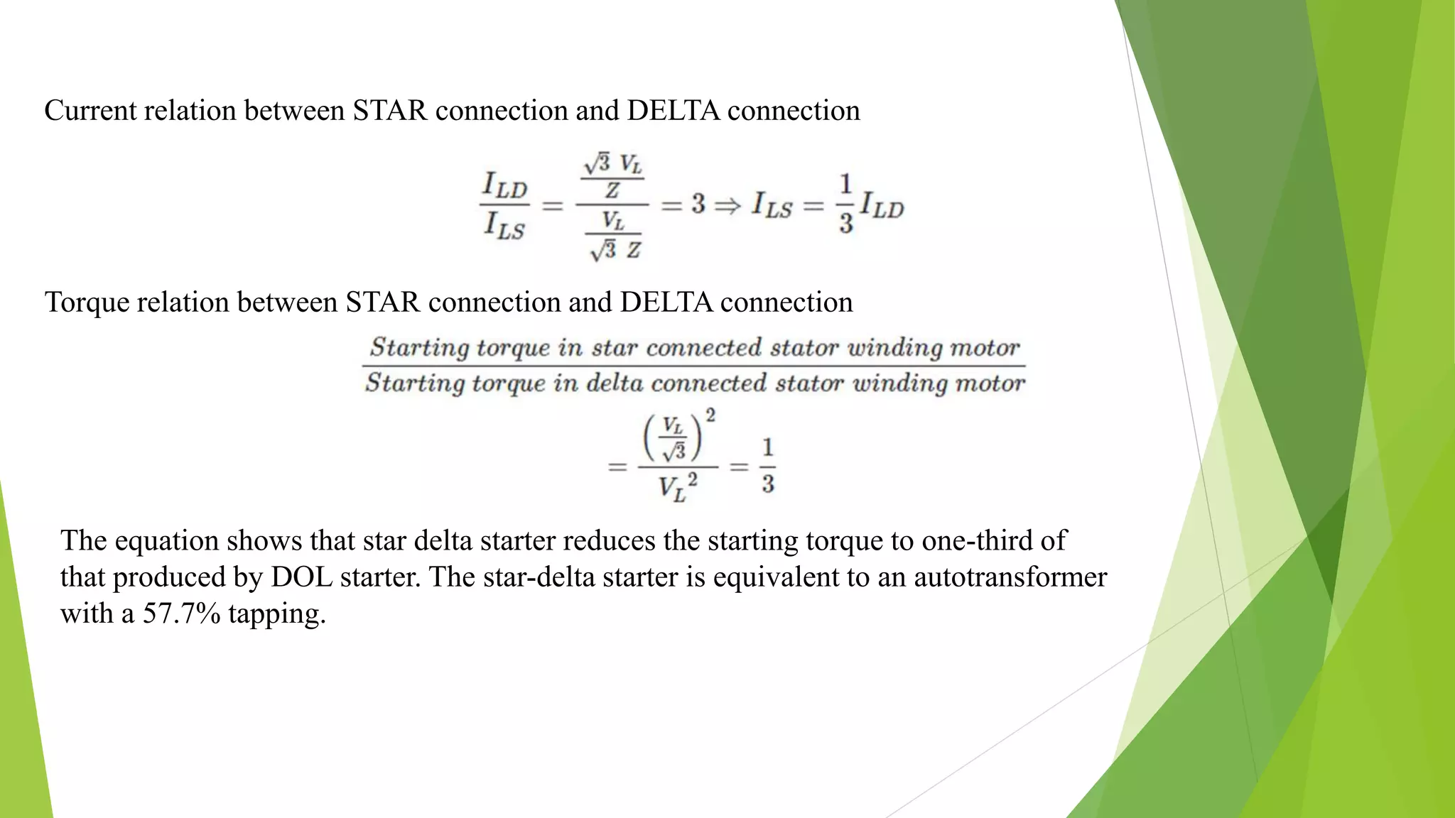
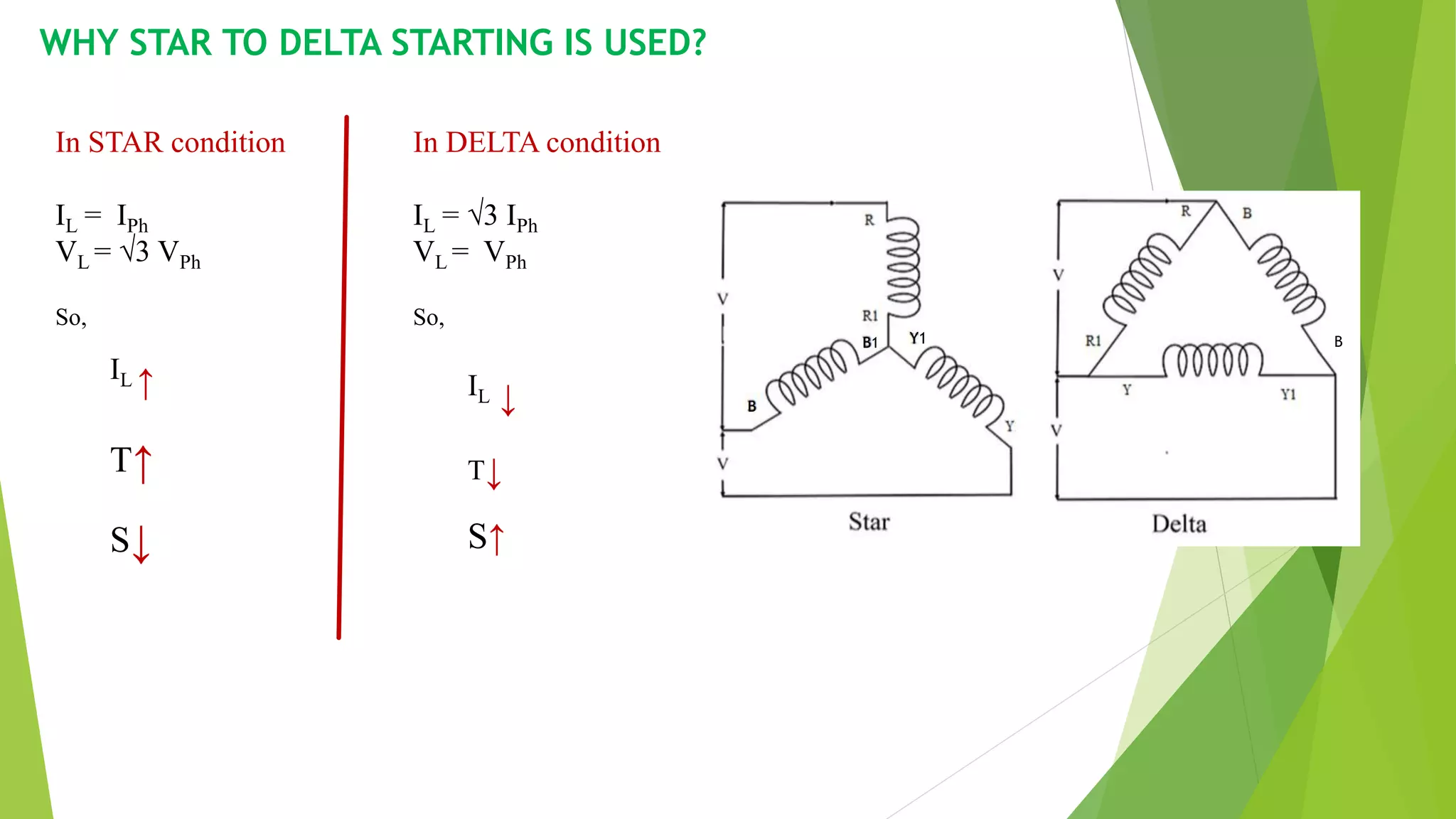
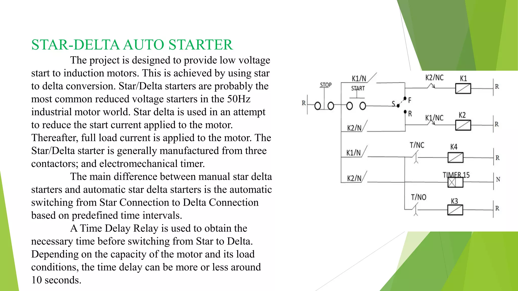
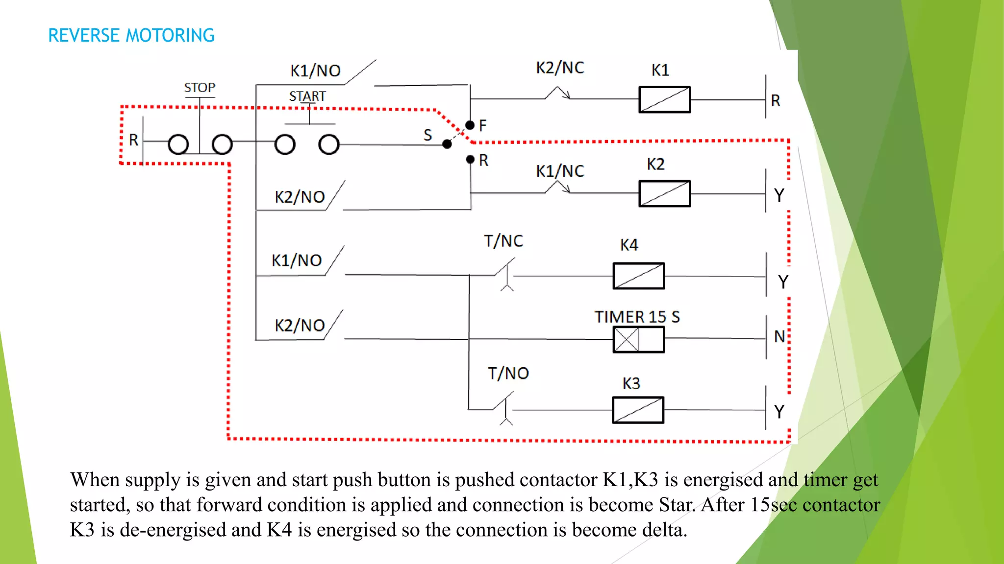
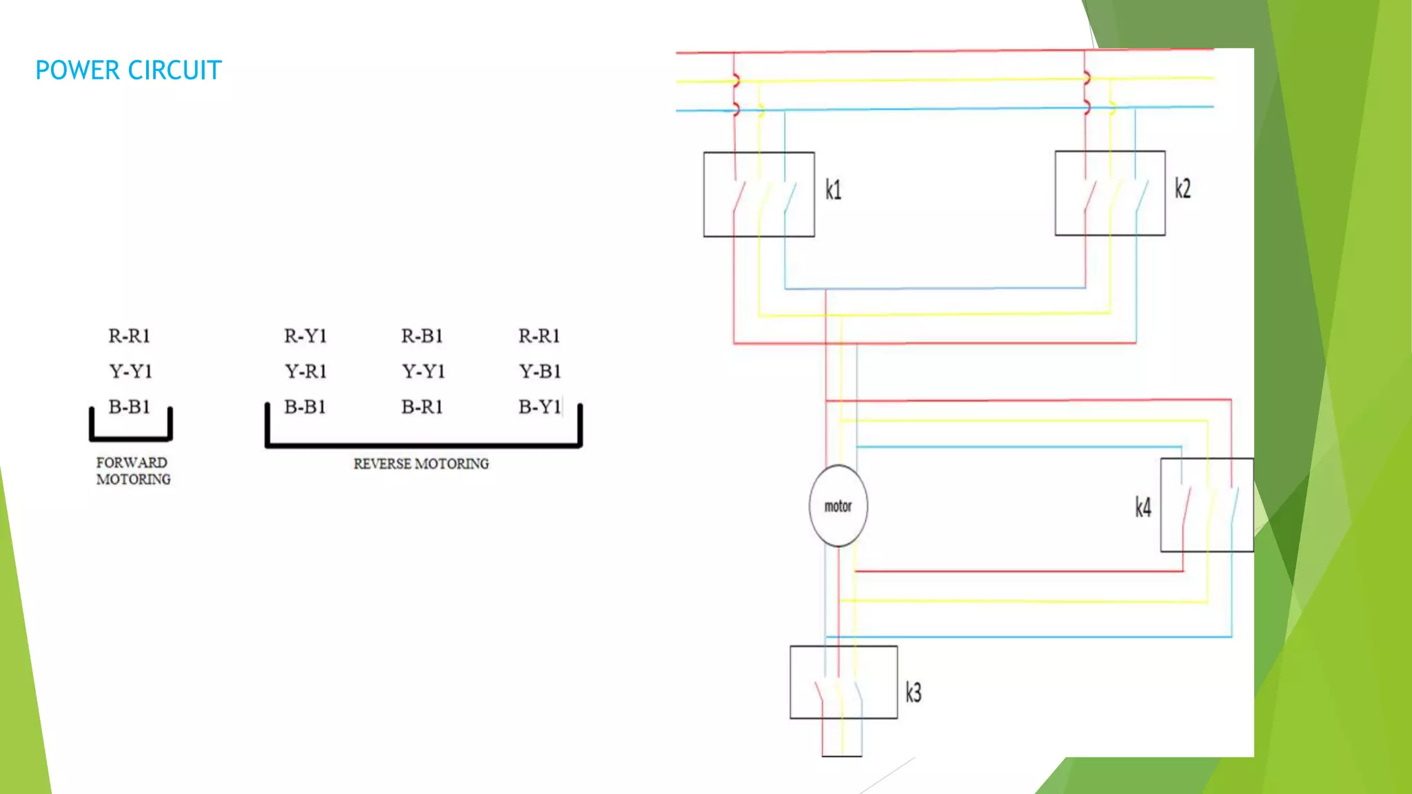
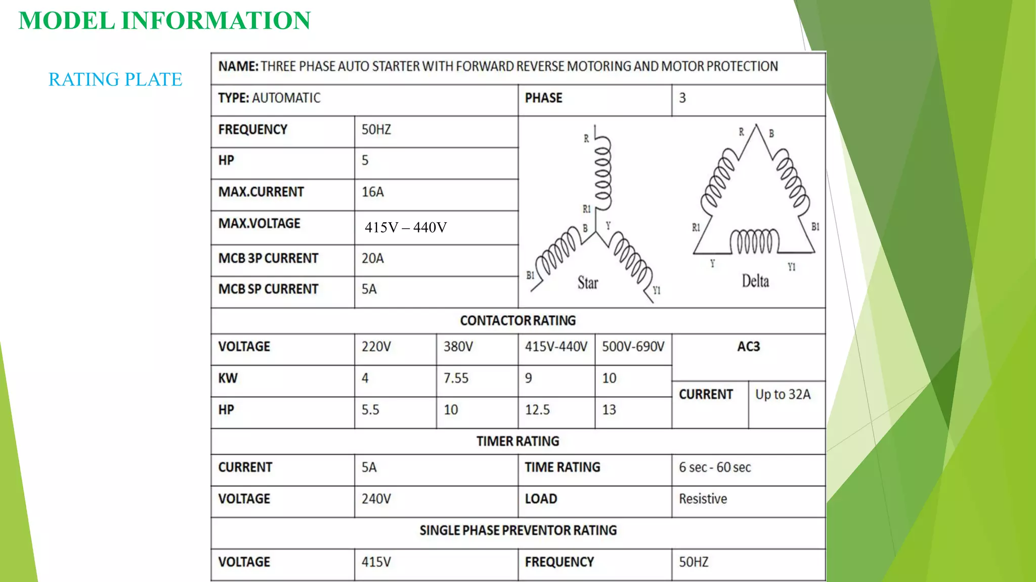
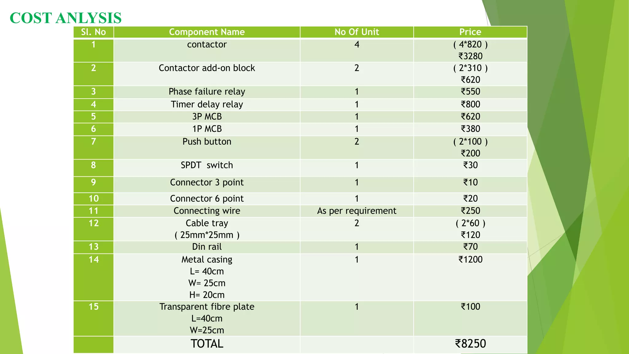
PROJECT GUIDE :-
Prof . Sibananda Mishra (HOD Dept.EE)
PREPAIRED BY:-
Bhupatibhakti manas Pradhan (1501298212)
Arabinda Sahoo (1621298008)
Jagannath Sahoo (1621298062)
Trilochan Gochhayat (1621298051)
CONTENTS
• INTRODUCTION
• OBJECTIVES OF PROJECT
• STAR DELTA STARTING OF MOTOR
• WHY STAR TO DELTA IS USED
• STAR-DELTAAUTO STARTER
• FORWARD AND REVERSE OPERATION OF MOTOR
• PROTECTION OF MOTOR
• COMPONENTS AND THEIR WORKING
• METHOD OF OPERATION
• STEPS TO OPERATE
• ADVANTAGES OF AUTO STARTER OVER DOL STARTER
• MODEL INFORMATION
• COST ANALYSIS
• CONCLUSION
• REFERENCES
INTRODUCTION
Main purpose of any starter is to reduce the requirement of high starting
current. Normally the starting current of an induction motor is 6 to 7 times of the full
load current. Starters are employed to reduce the starting current.
The forward reverse motor control is used in a system where forward and
backward or upward and downward movement in the operation are needed.
Forward and Reverse Operation of motor can be obtained by interchanging any two of
its three terminals.
Motor protection is used to prevent damage to the electrical motor, such as
internal faults in the motor. Faults like single phase protection, overload protection
and over current protection.
OBJECTIVES OF PROJECT
• Perform forward and reverse operation of motor.
• Auto starting of motor from star to delta.
• Single switch operation.
• Provide protection to the motor.
I. Single phase protection
II. Over current protection / Overload protection
III. Short circuit protection
STAR DELTA STARTING OF MOTOR
Star Delta Starter, which is sometimes called as Y – Δ Starter, is a common type of
Reduced Voltage Starter.
In a Star Delta Starter, the initial connection of the stator windings is in the form of Star.
As the motor accelerates and gains speed, the stator windings are disconnected from the Star
configuration and connected in the form of Delta.
The equation shows that star delta starter reduces the starting torque to one-third of
that produced by DOL starter. The star-delta starter is equivalent to an autotransformer
with a 57.7% tapping.
Current relation between STAR connection and DELTA connection
Torque relation between STAR connection and DELTA connection
WHY STAR TO DELTA STARTING IS USED?
In STAR condition
IL = IPh
VL = √3 VPh
So,
IL ↑
T↑
S↓
In DELTA condition
IL = √3 IPh
VL = VPh
So,
IL ↓
T↓
S↑
B1 B
B1
Y1
Advantages of Star Delta Starter
1. Inexpensive
2. No heat is produced, or tap changing device needs to be used, hence efficiency
increases.
3. Starting current reduced to 1/3 of direct online starting current.
4. Produce less torque.
5. Disadvantages of Star Delta Starter
6. Starting torque is reduced to 1/3 of full load torque.
7. A particular set of motors required.
STAR-DELTA AUTO STARTER
The project is designed to provide low voltage
start to induction motors. This is achieved by using star
to delta conversion. Star/Delta starters are probably the
most common reduced voltage starters in the 50Hz
industrial motor world. Star delta is used in an attempt
to reduce the start current applied to the motor.
Thereafter, full load current is applied to the motor. The
Star/Delta starter is generally manufactured from three
contactors; and electromechanical timer.
The main difference between manual star delta
starters and automatic star delta starters is the automatic
switching from Star Connection to Delta Connection
based on predefined time intervals.
A Time Delay Relay is used to obtain the
necessary time before switching from Star to Delta.
Depending on the capacity of the motor and its load
conditions, the time delay can be more or less around
10 seconds.
FORWARD AND REVERSE OPERATION OF MOTOR
The forward reverse motor control is used in a system where
forward and backward or upward and downward movement in the
operation are needed.
Forward and Reverse Operation of motor can be obtained by
interchanging any two of its three terminals.
PROTECTION OF MOTOR
1. Phase Loss Protection / Phase Imbalance Protection
A three-phase motor can continue operating if one of the phases is lost. However, this
causes a considerable mechanical stress on the equipment while also increasing the current of the
two operational phases. This condition may cause a motor to fail prematurely.
Protection against phase loss and imbalance is accomplished with an auxiliary circuit,
just like phase failure relay is used. Typically, phase imbalance must not exceed 2% in order to
guarantee optimal motor performance.
2.Over load / over current protection
An overload is a condition in which currents above the rated value are present, but
unlike a fault current, overloads may be of just a few amperes over the rated current.
Nevertheless, overloads can cause irreversible damage due to the amount of heat released.
3.Short-circuit protection
A short circuit occurs when current travels along an unintended path, often where
essentially no (or a very low) electrical impedance is encountered. Short circuit protection is
protection against excessive currents or current beyond the acceptable current rating of equipment
and it operates instantly. As soon as an overcurrent is detected, the device trips and breaks the
circuit.
4.Under Voltage Protection / Over Voltage Protection
Electric motors are designed to operate within a specific voltage range, and any voltage
outside that range will cause problems that shorten the service life of the motor:
• Under-voltage makes the motor draw a higher current, to be able to keep up with the
load. Over time, this damages the motor and it also causes the inrush current to be
higher.
• Over-voltage saturates the ferromagnetic cores, which also increases the line current.
5.Bidirectional protection
When a motor running in one direction it is impossible to reverse the direction of
motor immediately due to interlocking condition.
COMPONENTS AND THEIR WORKING
1.Contactor
Unlike general-purpose relays, contactors are designed
to be directly connected to high-current load devices. Relays
tend to be of lower capacity and are usually designed for
both normally closed and normally open applications. Unlike
relays, contactors are designed with features to control and
suppress the arc produced when interrupting heavy motor
currents.
when current passes through the electromagnet a
magnetic field is produced which attracts the moving core of the
contactor.
2.Timer
time delay relays (TDRs) can provide simple, reliable, and economical
control. Adjusting the delay time is often as simple as turning a knob. Providing
time-delayed switching to start a motor, control a load, or affect a process, TDRs
are typically used in industrial applications. Additionally, they play an important
role for targeted logic needs, such as in a small panel or in sub-panels. They have
a variety of features and operating characteristics, such as compactness,
economy, simplicity, and ease-of-use.
ON Delay timer
OFF Delay timer
3.Singlephase failure
The Phase Failure Relay is a phase-voltage-
balance monitoring device designed for use
with magnetic controls to automatically prevent
three phase motors or other equipment from
operating or attempting to start up under open
phase or single-phase conditions, thereby
eliminating burnouts and consequent down-time
frequently incurred by phase failure
Phase Failure Relay is not a thermal device.
It operates on the principle of phase voltage
unbalance which may occur in a three phase
system. It also protects against phase loss.
4.Miniature circuit breaker (MCB)
We use more commonly miniature circuit breaker or MCB in
low voltage electrical network instead of fuse. The MCB has some
advantages compared to fuse.
It automatically switches off the electrical circuit during
abnormal condition of the network means in over load condition as well
as faulty condition. The fuse does not sense but miniature circuit breaker
does it in more reliable way. MCB is much more sensitive to over
current than fuse.
The operating principle of MCB is simple. An MCB function
by interrupting the stability of electrical flow through the circuit once an
error is detected. In simple conditions this circuit breaker is a switch
which routinely turns off when the current flows through it and passes
the maximum acceptable limit.
3 Pole MCB
Single Pole MCB
5.DPDT Switch
6.Push button
In industrial and commercial applications, push buttons can be
connected together by a mechanical linkage so that the act of
pushing one button causes the other button to be released. In this
way, a stop button can "force" a start button to be released. This
method of linkage is used in simple manual operations in which the
machine or process has no electrical circuits for control.
7.Contactor Add-On block
It is used for adding an NO / NC to the contactor according to
the requirement. Add-on block work as an extension of
contactor.
8.Cable tray
In the electrical wiring of buildings, a cable tray system is used to support
insulated electrical cables used for power distribution, control, and communication.
Cable trays are used as an alternative to open wiring or electrical conduit systems, and
are commonly used for cable management in commercial and industrial construction.
9.Din rail
A DIN rail is a metal rail of a standard type widely used for mounting circuit
breakers and industrial control equipment inside equipment racks. These
products are typically made from cold rolled carbon steel sheet with a zinc-
plated or chromated bright surface finish. Although metallic, they are meant
only for mechanical support, and are not used as a bus bar to conduct electric
current, although they may provide a chassis grounding connection
10.Metal casing
Metal casing means a
structure made up of metal where the
components are placed for safety and
maintenance purposes.
L= 40cm
W= 25cm
H= 20cm
11.Connector
A connector is a device used to join
electrical circuits and are also referred to
as electrical connectors.
METHOD OF OPERATION
In this starter there is two type of connection is established, one is called control circuit and
another is power circuit.
Control circuit is for controlling and switching purposes. And power circuit is used for three phase
supply according to requirement.
CONTROL CIRCUIT
K1- Contactor 1 S- Selector switch
K2- Contactor 2 F- Forward motoring
K3- Contactor 3 R- Reverse motoring
K4- Contactor 4
NO- Normally Open
NC- Normally close
S- Selector switch
F- Forward motoring
R- Reverse motoring
n
e
FORWARD MOTORING
When supply is given and start push button is pushed contactor K1,K3 is energised and
timer get started, so that forward condition is applied and connection is become Star.
After 15sec contactor K3 is de-energised and K4 is energised so the connection is
become delta.
Y
Y
Y
Y
REVERSE MOTORING
When supply is given and start push button is pushed contactor K1,K3 is energised and timer get
started, so that forward condition is applied and connection is become Star. After 15sec contactor
K3 is de-energised and K4 is energised so the connection is become delta.
Y
Y
Y
POWER CIRCUIT
STEPS TO OPERATE
Step 1: Provide the supply to the circuit.
Step 1: Select the mode of operation i.e. forward motoring or reverse motoring by using a SPDT switch.
Step 2: Check the phase failure relay, whether red LED is glowing or not. If LED is turn red then everything is
ok to start the process, otherwise there is a fault in three phase supply.
Step 3: Start the process by pushing START push button.
Step 3: Wait 15sec to turn the connection from star to delta automatically.
Step 4: After the work is done press the Stop push button.
ADVANTAGES OF AUTO STARTER OVER DOL STARTER
• It is an automatic process where Start connection is converted to Delta
connection automatically after 15sec.
• Star Delta auto starter reduces the starting torque 1/3 of the DOL starter.
• Due to inter-locking system when a motor is running in on direction , It is
impossible to reverse the direction of motor by switching the SPDT switch.
• Single switch operation.
• Operation is smooth and simple.
• It provides protection to the motor followed by the auto starter.
• It is modified easily according to the motor requirement.
• Low maintenance.
MODEL INFORMATION
RATING PLATE
415V – 440V
PHYSICAL OVERVIEW
COST ANLYSIS
Sl. No Component Name No Of Unit Price
1 contactor 4 ( 4*820 )
₹3280
2 Contactor add-on block 2 ( 2*310 )
₹620
3 Phase failure relay 1 ₹550
4 Timer delay relay 1 ₹800
5 3P MCB 1 ₹620
6 1P MCB 1 ₹380
7 Push button 2 ( 2*100 )
₹200
8 SPDT switch 1 ₹30
9 Connector 3 point 1 ₹10
10 Connector 6 point 1 ₹20
11 Connecting wire As per requirement ₹250
12 Cable tray
( 25mm*25mm )
2 ( 2*60 )
₹120
13 Din rail 1 ₹70
14 Metal casing
L= 40cm
W= 25cm
H= 20cm
1 ₹1200
15 Transparent fibre plate
L=40cm
W=25cm
1 ₹100
TOTAL ₹8250
CONCLUSION
In this project a three phase device is designed or constructed, due to
which starting of a three phase sq cage induction motor is done automatically. It
also gives an option to choose between forward motoring and reverse motoring. In
other hand it provides protection to the motor.
Three phase auto starter converts STAR connection into DELTA
connection after 15sec from the starting of device. Star Delta auto starter reduces
the starting torque 1/3 of the DOL starter.
It provides options to select forward motoring and reverse motoring
according to the requirement.
In addition to this process it provides the protection to the three phase
motor are; Phase protection, over voltage protection, over current protection, short
circuit protection , Bidirectional protection .etc.
REFERENCES
• STAR-DELTA STARTER ,Islamic university of gaza,PLC lab, Eng.Mohammed s. jouda.
• ENERGY CONSERVATION USING STAR-DELTA STARTER, IRJET, D.M. Bokde, S.S.
Jalkote, M.V. Birajdar, Asst. Prof. R.S.Biradar.
• AUTOMATIC STAR DELTA STARTER USING RELAY AND ADJUSTABLE
ELECTRONIC TIMER FOR 3 PHASE INDUCTION MOTOR ,Apoorva, anurag dwivedi,
vishwas chaudhri, pradnya chauhan, R.s. deasi.
• AUTOMATIC STAR DELTA STARTER USING RELAY WITH AN ELECTRONIC
ADJUSTABLE TIMER,TRPCS, Swapnil R. Badge, Nitin M. Sonune, Akshay P. Wakekar,
Hemant S. Ulmale, Rugved R. Deshmukh.
• THREE PHASE INDUCTION MOTOR, module 8, IIT Kharagpur.
• ELECTRICAL MACHINE-II,vssut.
• CLOSE DIFFERENTIAL UNDER VOLTAGE RELAY, LAKESHORE electric corporation.
• PHASE FAILURE RELAY, RMS technology.
• PHASE FAILURE RELAY-PHASE PHEE, Prok devices private limited.
• TIMER AND TIMES SWITCHES, CSM technology.
• CONTACTORS AND RELAYS, Eaton wiring manual 06/11.
• MOTOR PROTECTION PRINCIPLES, craig wester, ge multilin.
• AN INTRODUCTION TO ELECTRIC MOTORS, life augmented.
ANY
QUERY ?

star delta auto starter with forward reverse and motor protection

  • 2.
    PROJECT GUIDE :- Prof. Sibananda Mishra (HOD Dept.EE) PREPAIRED BY:- Bhupatibhakti manas Pradhan (1501298212) Arabinda Sahoo (1621298008) Jagannath Sahoo (1621298062) Trilochan Gochhayat (1621298051)
  • 3.
    CONTENTS • INTRODUCTION • OBJECTIVESOF PROJECT • STAR DELTA STARTING OF MOTOR • WHY STAR TO DELTA IS USED • STAR-DELTAAUTO STARTER • FORWARD AND REVERSE OPERATION OF MOTOR • PROTECTION OF MOTOR • COMPONENTS AND THEIR WORKING • METHOD OF OPERATION • STEPS TO OPERATE • ADVANTAGES OF AUTO STARTER OVER DOL STARTER • MODEL INFORMATION • COST ANALYSIS • CONCLUSION • REFERENCES
  • 4.
    INTRODUCTION Main purpose ofany starter is to reduce the requirement of high starting current. Normally the starting current of an induction motor is 6 to 7 times of the full load current. Starters are employed to reduce the starting current. The forward reverse motor control is used in a system where forward and backward or upward and downward movement in the operation are needed. Forward and Reverse Operation of motor can be obtained by interchanging any two of its three terminals. Motor protection is used to prevent damage to the electrical motor, such as internal faults in the motor. Faults like single phase protection, overload protection and over current protection.
  • 5.
    OBJECTIVES OF PROJECT •Perform forward and reverse operation of motor. • Auto starting of motor from star to delta. • Single switch operation. • Provide protection to the motor. I. Single phase protection II. Over current protection / Overload protection III. Short circuit protection
  • 6.
    STAR DELTA STARTINGOF MOTOR Star Delta Starter, which is sometimes called as Y – Δ Starter, is a common type of Reduced Voltage Starter. In a Star Delta Starter, the initial connection of the stator windings is in the form of Star. As the motor accelerates and gains speed, the stator windings are disconnected from the Star configuration and connected in the form of Delta.
  • 7.
    The equation showsthat star delta starter reduces the starting torque to one-third of that produced by DOL starter. The star-delta starter is equivalent to an autotransformer with a 57.7% tapping. Current relation between STAR connection and DELTA connection Torque relation between STAR connection and DELTA connection
  • 8.
    WHY STAR TODELTA STARTING IS USED? In STAR condition IL = IPh VL = √3 VPh So, IL ↑ T↑ S↓ In DELTA condition IL = √3 IPh VL = VPh So, IL ↓ T↓ S↑ B1 B B1 Y1
  • 9.
    Advantages of StarDelta Starter 1. Inexpensive 2. No heat is produced, or tap changing device needs to be used, hence efficiency increases. 3. Starting current reduced to 1/3 of direct online starting current. 4. Produce less torque. 5. Disadvantages of Star Delta Starter 6. Starting torque is reduced to 1/3 of full load torque. 7. A particular set of motors required.
  • 10.
    STAR-DELTA AUTO STARTER Theproject is designed to provide low voltage start to induction motors. This is achieved by using star to delta conversion. Star/Delta starters are probably the most common reduced voltage starters in the 50Hz industrial motor world. Star delta is used in an attempt to reduce the start current applied to the motor. Thereafter, full load current is applied to the motor. The Star/Delta starter is generally manufactured from three contactors; and electromechanical timer. The main difference between manual star delta starters and automatic star delta starters is the automatic switching from Star Connection to Delta Connection based on predefined time intervals. A Time Delay Relay is used to obtain the necessary time before switching from Star to Delta. Depending on the capacity of the motor and its load conditions, the time delay can be more or less around 10 seconds.
  • 11.
    FORWARD AND REVERSEOPERATION OF MOTOR The forward reverse motor control is used in a system where forward and backward or upward and downward movement in the operation are needed. Forward and Reverse Operation of motor can be obtained by interchanging any two of its three terminals.
  • 12.
    PROTECTION OF MOTOR 1.Phase Loss Protection / Phase Imbalance Protection A three-phase motor can continue operating if one of the phases is lost. However, this causes a considerable mechanical stress on the equipment while also increasing the current of the two operational phases. This condition may cause a motor to fail prematurely. Protection against phase loss and imbalance is accomplished with an auxiliary circuit, just like phase failure relay is used. Typically, phase imbalance must not exceed 2% in order to guarantee optimal motor performance. 2.Over load / over current protection An overload is a condition in which currents above the rated value are present, but unlike a fault current, overloads may be of just a few amperes over the rated current. Nevertheless, overloads can cause irreversible damage due to the amount of heat released. 3.Short-circuit protection A short circuit occurs when current travels along an unintended path, often where essentially no (or a very low) electrical impedance is encountered. Short circuit protection is protection against excessive currents or current beyond the acceptable current rating of equipment and it operates instantly. As soon as an overcurrent is detected, the device trips and breaks the circuit.
  • 13.
    4.Under Voltage Protection/ Over Voltage Protection Electric motors are designed to operate within a specific voltage range, and any voltage outside that range will cause problems that shorten the service life of the motor: • Under-voltage makes the motor draw a higher current, to be able to keep up with the load. Over time, this damages the motor and it also causes the inrush current to be higher. • Over-voltage saturates the ferromagnetic cores, which also increases the line current. 5.Bidirectional protection When a motor running in one direction it is impossible to reverse the direction of motor immediately due to interlocking condition.
  • 14.
    COMPONENTS AND THEIRWORKING 1.Contactor Unlike general-purpose relays, contactors are designed to be directly connected to high-current load devices. Relays tend to be of lower capacity and are usually designed for both normally closed and normally open applications. Unlike relays, contactors are designed with features to control and suppress the arc produced when interrupting heavy motor currents. when current passes through the electromagnet a magnetic field is produced which attracts the moving core of the contactor.
  • 15.
    2.Timer time delay relays(TDRs) can provide simple, reliable, and economical control. Adjusting the delay time is often as simple as turning a knob. Providing time-delayed switching to start a motor, control a load, or affect a process, TDRs are typically used in industrial applications. Additionally, they play an important role for targeted logic needs, such as in a small panel or in sub-panels. They have a variety of features and operating characteristics, such as compactness, economy, simplicity, and ease-of-use. ON Delay timer OFF Delay timer
  • 16.
    3.Singlephase failure The PhaseFailure Relay is a phase-voltage- balance monitoring device designed for use with magnetic controls to automatically prevent three phase motors or other equipment from operating or attempting to start up under open phase or single-phase conditions, thereby eliminating burnouts and consequent down-time frequently incurred by phase failure Phase Failure Relay is not a thermal device. It operates on the principle of phase voltage unbalance which may occur in a three phase system. It also protects against phase loss.
  • 17.
    4.Miniature circuit breaker(MCB) We use more commonly miniature circuit breaker or MCB in low voltage electrical network instead of fuse. The MCB has some advantages compared to fuse. It automatically switches off the electrical circuit during abnormal condition of the network means in over load condition as well as faulty condition. The fuse does not sense but miniature circuit breaker does it in more reliable way. MCB is much more sensitive to over current than fuse. The operating principle of MCB is simple. An MCB function by interrupting the stability of electrical flow through the circuit once an error is detected. In simple conditions this circuit breaker is a switch which routinely turns off when the current flows through it and passes the maximum acceptable limit. 3 Pole MCB Single Pole MCB
  • 18.
    5.DPDT Switch 6.Push button Inindustrial and commercial applications, push buttons can be connected together by a mechanical linkage so that the act of pushing one button causes the other button to be released. In this way, a stop button can "force" a start button to be released. This method of linkage is used in simple manual operations in which the machine or process has no electrical circuits for control.
  • 19.
    7.Contactor Add-On block Itis used for adding an NO / NC to the contactor according to the requirement. Add-on block work as an extension of contactor. 8.Cable tray In the electrical wiring of buildings, a cable tray system is used to support insulated electrical cables used for power distribution, control, and communication. Cable trays are used as an alternative to open wiring or electrical conduit systems, and are commonly used for cable management in commercial and industrial construction. 9.Din rail A DIN rail is a metal rail of a standard type widely used for mounting circuit breakers and industrial control equipment inside equipment racks. These products are typically made from cold rolled carbon steel sheet with a zinc- plated or chromated bright surface finish. Although metallic, they are meant only for mechanical support, and are not used as a bus bar to conduct electric current, although they may provide a chassis grounding connection
  • 20.
    10.Metal casing Metal casingmeans a structure made up of metal where the components are placed for safety and maintenance purposes. L= 40cm W= 25cm H= 20cm 11.Connector A connector is a device used to join electrical circuits and are also referred to as electrical connectors.
  • 21.
    METHOD OF OPERATION Inthis starter there is two type of connection is established, one is called control circuit and another is power circuit. Control circuit is for controlling and switching purposes. And power circuit is used for three phase supply according to requirement. CONTROL CIRCUIT K1- Contactor 1 S- Selector switch K2- Contactor 2 F- Forward motoring K3- Contactor 3 R- Reverse motoring K4- Contactor 4 NO- Normally Open NC- Normally close S- Selector switch F- Forward motoring R- Reverse motoring n e
  • 22.
    FORWARD MOTORING When supplyis given and start push button is pushed contactor K1,K3 is energised and timer get started, so that forward condition is applied and connection is become Star. After 15sec contactor K3 is de-energised and K4 is energised so the connection is become delta. Y Y Y Y
  • 23.
    REVERSE MOTORING When supplyis given and start push button is pushed contactor K1,K3 is energised and timer get started, so that forward condition is applied and connection is become Star. After 15sec contactor K3 is de-energised and K4 is energised so the connection is become delta. Y Y Y
  • 24.
  • 25.
    STEPS TO OPERATE Step1: Provide the supply to the circuit. Step 1: Select the mode of operation i.e. forward motoring or reverse motoring by using a SPDT switch. Step 2: Check the phase failure relay, whether red LED is glowing or not. If LED is turn red then everything is ok to start the process, otherwise there is a fault in three phase supply. Step 3: Start the process by pushing START push button. Step 3: Wait 15sec to turn the connection from star to delta automatically. Step 4: After the work is done press the Stop push button.
  • 26.
    ADVANTAGES OF AUTOSTARTER OVER DOL STARTER • It is an automatic process where Start connection is converted to Delta connection automatically after 15sec. • Star Delta auto starter reduces the starting torque 1/3 of the DOL starter. • Due to inter-locking system when a motor is running in on direction , It is impossible to reverse the direction of motor by switching the SPDT switch. • Single switch operation. • Operation is smooth and simple. • It provides protection to the motor followed by the auto starter. • It is modified easily according to the motor requirement. • Low maintenance.
  • 27.
  • 28.
  • 29.
    COST ANLYSIS Sl. NoComponent Name No Of Unit Price 1 contactor 4 ( 4*820 ) ₹3280 2 Contactor add-on block 2 ( 2*310 ) ₹620 3 Phase failure relay 1 ₹550 4 Timer delay relay 1 ₹800 5 3P MCB 1 ₹620 6 1P MCB 1 ₹380 7 Push button 2 ( 2*100 ) ₹200 8 SPDT switch 1 ₹30 9 Connector 3 point 1 ₹10 10 Connector 6 point 1 ₹20 11 Connecting wire As per requirement ₹250 12 Cable tray ( 25mm*25mm ) 2 ( 2*60 ) ₹120 13 Din rail 1 ₹70 14 Metal casing L= 40cm W= 25cm H= 20cm 1 ₹1200 15 Transparent fibre plate L=40cm W=25cm 1 ₹100 TOTAL ₹8250
  • 30.
    CONCLUSION In this projecta three phase device is designed or constructed, due to which starting of a three phase sq cage induction motor is done automatically. It also gives an option to choose between forward motoring and reverse motoring. In other hand it provides protection to the motor. Three phase auto starter converts STAR connection into DELTA connection after 15sec from the starting of device. Star Delta auto starter reduces the starting torque 1/3 of the DOL starter. It provides options to select forward motoring and reverse motoring according to the requirement. In addition to this process it provides the protection to the three phase motor are; Phase protection, over voltage protection, over current protection, short circuit protection , Bidirectional protection .etc.
  • 31.
    REFERENCES • STAR-DELTA STARTER,Islamic university of gaza,PLC lab, Eng.Mohammed s. jouda. • ENERGY CONSERVATION USING STAR-DELTA STARTER, IRJET, D.M. Bokde, S.S. Jalkote, M.V. Birajdar, Asst. Prof. R.S.Biradar. • AUTOMATIC STAR DELTA STARTER USING RELAY AND ADJUSTABLE ELECTRONIC TIMER FOR 3 PHASE INDUCTION MOTOR ,Apoorva, anurag dwivedi, vishwas chaudhri, pradnya chauhan, R.s. deasi. • AUTOMATIC STAR DELTA STARTER USING RELAY WITH AN ELECTRONIC ADJUSTABLE TIMER,TRPCS, Swapnil R. Badge, Nitin M. Sonune, Akshay P. Wakekar, Hemant S. Ulmale, Rugved R. Deshmukh. • THREE PHASE INDUCTION MOTOR, module 8, IIT Kharagpur. • ELECTRICAL MACHINE-II,vssut. • CLOSE DIFFERENTIAL UNDER VOLTAGE RELAY, LAKESHORE electric corporation. • PHASE FAILURE RELAY, RMS technology. • PHASE FAILURE RELAY-PHASE PHEE, Prok devices private limited. • TIMER AND TIMES SWITCHES, CSM technology. • CONTACTORS AND RELAYS, Eaton wiring manual 06/11. • MOTOR PROTECTION PRINCIPLES, craig wester, ge multilin. • AN INTRODUCTION TO ELECTRIC MOTORS, life augmented.
  • 33.