Three main microgrid control strategies are described:
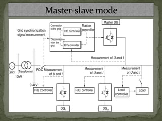
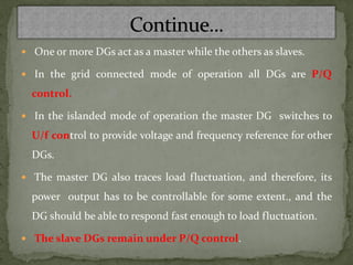
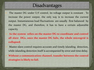
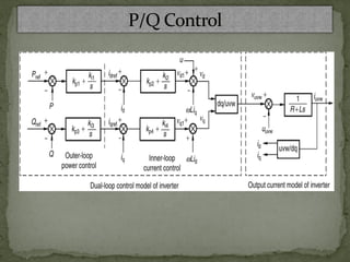
1. Master-slave mode where one DG acts as the voltage/frequency master and others follow as slaves under P/Q control.
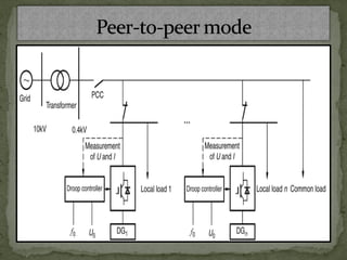
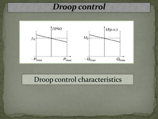
2. Peer-to-peer mode where all DGs use droop control to cooperatively regulate voltage and frequency without a master.
3. Combined mode using aspects of both by assigning control roles based on DG type.
These slides presents the different challenges and issues related to DG integration to Micro-grid distribution systems. The possible solutions are also presented. Later of the class I will try to upload the mathematical presentations and simulation results related to each protection scheme. However, your suggestions are always welcome.
This slide presents an introduction to microgrid. This is the second class for the subject 'Distribution Generation and Smart Grid'. Class wise I will provide all the discussions and analysis.
In microgrid, if fault occurs or any other contingency happens, then the problems would be created which are related to power flow, also there are various protection schemes are used for minimize or eliminate these problems.
Voltage control is used for reactive power balance and P-f control is used for active power control.
Various protection schemes such as, over current protection, differential protection scheme, zoning of network in adaptive protection scheme are used in microgrid system .
Role of storage in smart grid
Different types of storage technologies
USE OF BATTERIES IN GRID
TYPES OF BATTERIES
SMES {SUPERCONDUCTING MAGNETIC ENERGY STORAGE}
Communication, Measurement and Monitoring Technologies for Smart Grid
Real time pricing
Smart Meters
CLOUD Computing
cyber security for smart grid
Phasor Measurement Units (PMU)
Design & Analysis of Grid Connected Photovoltaic SystemSulaman Muhammad
Aim of this project was to boost the DC voltage generated by the photovoltaic system to the required DC value through DC-DC boost converter and then to invert that DC voltage to AC voltage through H-bridge inverter. The output of the inverter is then filtered through a low pass filter to get a pure sinusoidal wave form. This output is then synchronized with the grid by converting the sine wave of grid into square wave and then compare that square wave with the PWM and then give that output wave of comparator to H-bridge, so if there is any change in the grid as a result the output of inverter will also have same change.
Smart Grid: Definition
• Need of smart grid
• Smart grid functions
• How Smart Grid Works
• Smart Grid: Benefits
• Smart grid components and its Benefits
• Issues and Challenges
• Opportunities in future
• Smart Grid Projects in India and Gujarat
• Question-Answer
• References
What is islanding ?
Consider the power network as shown in fig.1
Now if we disconnect the line AB from the infinite transmission grid there will be an isolated region . The D1, D2 are power sources (eg : inverter , solar power cells ). The power generated in this region is fed to the island only.
We see that there no longer is any control over the island voltage at the bus X . Also there is no mechanism here for control of frequency.
This state is referred to as islanding.
Smart Grid
Why do we need Smart Grid?
What is Smart Grid?
Smart Grid conceptual model
Wide Area Monitoring systems
What is WAMs
WAMS Architecture
Applications of Phasor Measurement Unit (PMU)
Concluding Remarks
As the world’s electricity systems face a number of challenges
such as
New dynamics of future demand and supply
Ageing infrastructure
Complex interconnected grids
Integration of large number of renewable generation sources
Need to lower carbon emissions
New type of loads such as Electric Vehicles
Exponential growth in the energy demand on account of rising population and economic growth,
increasing apprehensions of energy security coupled with climate change and global warming concerns are some
of the major drivers for pushing the renewable energy (RE) to the top of the energy portfolio. Among various
renewable energy resources, wind and solar PV systems are experiencing rapid growth since 2010. By the end of
2016, the world total capacity of wind power generation was 487 GW and that of solar PV was 303 GW,
aggregating to a penetration level of 4.0% and 1.5% respectively. Global renewable energy penetration till Dec.
2016, excluding conventional hydro share (of 16.6%) was only around 8.0%. However, many countries have set
target of 30% RE based electricity generation by 2030. India has an ambitious target of achieving 175 GW of RE
power by 2022, with 100 GW from solar, 60 GW from wind, 10 GW from biomass and 5 GW from small hydro.
Power generation from renewables often takes place through distributed generation (DG). These units, mostly
located in remote locations, are not centrally planned or dispatched, and are usually connected to distribution grids
at LV or MV levels. In few cases, large capacity RE generation are also connected to transmission networks. As a
result, the power generation structure is moving from the large, centralized plants to a mixed generation pool
consisting of traditional large plants and many smaller DG units. Most of the RE generators have electrical
characteristics that are different from the synchronous machines. Since a large group of DG technologies use
power electronics converters for grid connectivity, they introduce many technical issues related to the operation,
control and protection of the power system, impacting generators, transmission system and consumer devices.
This paper presents some of the technical issues and challenges that need to be addressed for the effective
grid integration of RE based power generators so that eventually, our reliance on polluting and expensive fossilbased
hydro-carbon driven power generation can be reduced substantially.
Phasor measurement unit and it's application pptKhurshid Parwez
The effective operation of power systems in the present and the future depends to a large extent on how well the emerging challenges are met today. Power systems continue to be stressed as they are operated in many instances at or near their full capacities. In order to keep power systems operating in secure and economic conditions, it is necessary to further improve power system protection and control system. Phasor measurement unit (PMUs), introduced into power system as a useful tool for monitoring the performance of power system, has been proved its value in the extensive applications of electric power system. In response, a research program that is specifically aimed at using PMU to improve the power system protection and control. To ensure that the proposed research program is responsive to particular industry needs in this area, and participants of the workshop identified two major research areas in which technological and institutional solutions are needed: 1) PMU implementation, 2) PMU applications. It’s recommends research, design, and development (RD&D) projects in this report. The objective of these projects is to improve the reliability of local and wide transmission grid by enabling and enhancing the system protection and control schemes by using PMU measurement data, reduce the economic burden of utilizes to implement PMUs.
IJERA (International journal of Engineering Research and Applications) is International online, ... peer reviewed journal. For more detail or submit your article, please visit www.ijera.com
International Journal of Engineering Research and Applications (IJERA) is an open access online peer reviewed international journal that publishes research and review articles in the fields of Computer Science, Neural Networks, Electrical Engineering, Software Engineering, Information Technology, Mechanical Engineering, Chemical Engineering, Plastic Engineering, Food Technology, Textile Engineering, Nano Technology & science, Power Electronics, Electronics & Communication Engineering, Computational mathematics, Image processing, Civil Engineering, Structural Engineering, Environmental Engineering, VLSI Testing & Low Power VLSI Design etc.
This presentation begins with a discussion of the generator as a source feeding a very large remote system (the "single-machine infinite-bus" representation).
In the past few years we have experienced big disturbances in
the power system which caused complete blackout and million
of users including industry have suffered big economical
losses. These disturbances cause big oscillations in active and
reactive power, low voltage, voltage instability and phase or
angular instability between the generated and consumed power
which results in loss of generation and load which effected both
the power generation and the end customers.
During the steady state condition, power systems operate on
the nominal frequency (50Hz or 60Hz). The complete synchronism
of nominal frequency and voltage at the sending and
receiving ends cause complete balance of active and reactive
power between generated and consumed active and reactive
powers. In steady state operating condition Frequency=
Nominal frequency (50 or 60 Hz) +/– 0.02 Hz and
Voltage=Nominal voltage +/– 5% [1].
Power system faults, line switching, generator disconnection,
and the loss or application of large blocks of load result in
sudden changes to electrical power, which is due to the causes
shown
What is Power Swing | Power Swing What is Power Swing | Power Swing What is Power Swing | Power Swing What is Power Swing | Power Swing What is Power Swing | Power Swing What is Power Swing | Power Swing What is Power Swing | Power Swing What is Power Swing | Power Swing What is Power Swing | Power Swing What is Power Swing | Power Swing What is Power Swing | Power Swing What is Power Swing | Power Swing What is Power Swing | Power Swing What is Power Swing | Power Swing What is Power Swing | Power Swing What is Power Swing | Power Swing What is Power Swing | Power Swing What is Power Swing | Power Swing What is Power Swing | Power Swing What is Power Swing | Power Swing What is Power Swing | Power Swing What is Power Swing | Power Swing What is Power Swing | Power Swing What is Power Swing | Power Swing What is Power Swing | Power Swing What is Power Swing | Power Swing What is Power Swing | Power Swing What is Power Swing | Power Swing What is Power Swing | Power Swing What is Power Swing | Power Swing What is Power Swing | Power Swing What is Power Swing | Power Swing What is Power Swing | Power Swing What is Power Swing | Power Swing What is Power Swing | Power Swing What is Power Swing | Power Swing What is Power Swing | Power Swing What is Power Swing | Power Swing What is Power Swing | Power Swing What is Power Swing | Power Swing What is Power Swing | Power Swing What is Power Swing | Power Swing What is Power Swing | Power Swing What is Power Swing | Power Swing What is Power Swing | Power Swing What is Power Swing | Power Swing What is Power Swing | Power Swing What is Power Swing | Power Swing What is Power Swing | Power Swing What is Power Swing | Power Swing What is Power Swing | Power Swing
Power System Frequency Power System Frequency Power System Frequency Power System Frequency Power System Frequency Power System Frequency Power System Frequency Power System Frequency Power System Frequency Power System Frequency Power System Frequency Power System Frequency Power System Frequency Power System Frequency Power System Frequency Power System Frequency Power System Frequency Power System Frequency Power System Frequency Power System Frequency Power System Frequency Power System Frequency Power System Frequency Power System Frequency Power System Frequency Power System Frequency Power System Frequency Power System Frequency Power System Frequency Power System Frequency Power System Frequency Power System Frequency Power System Frequency Power System Frequency Power System Frequency Power System Frequency Power System Frequency Power System Frequency Power System Frequency Power System Frequency Power System Frequency Power System Frequency Power System Frequency Power System Frequency Power System Frequency Power System Frequency Power System Frequency Power System Frequency Power System Frequency Power System Frequency Power System Frequency Power System Frequency
In electric power systems that serve the load continuously should the voltage and frequency must remain constant, but if there is interference on one of the generators or the rail, then it is undeniable there will be disruption to the power supply. It is necessary to conduct a Research on the Stability of Power Systems relating to the Determination of Critical Breaking Angle and Critical Breaker Time on the generator, to find out how much the Critical Breaker Angle and how much
Stabilization and Frequency Regulation in Microgrid by Controlling Pitch Angleijtsrd
PID controller based pitch angle controller for the frequency regulation and active power control in a wind turbine and diesel engine powered hybrid power system, is presented in this paper. For testing the prosed controller, variable wind speed pattern is used for realization of real time wind behavior. Furthermore, the variable load is also connected to the hybrid power system to test the efficacy of the prosed controller. The system is modelled and simulated in MATLAB environment and results obtained are compared with and without pitch angle controller. The frequency deviations in PID based pitch angle controller is less than the without controller. Aman Malik | Kavita Sharma "Stabilization and Frequency Regulation in Microgrid by Controlling Pitch Angle" Published in International Journal of Trend in Scientific Research and Development (ijtsrd), ISSN: 2456-6470, Volume-4 | Issue-6 , October 2020, URL: https://www.ijtsrd.com/papers/ijtsrd33303.pdf Paper Url: https://www.ijtsrd.com/engineering/electrical-engineering/33303/stabilization-and-frequency-regulation-in-microgrid-by-controlling-pitch-angle/aman-malik
Introduction
Inter-area oscillations involve wide areas of the power grid and numerous power system components. Therefore, identifying the components influencing negatively the oscillations damping is extremely important. Power system oscillations usually contain multiple frequency components (modes), which are determined by generator inertia, transmission line impedance, governor, and excitation control, etc.
The oscillation behavior is sensitive to the following parameters:
The load model
The operating conditions
The presence of fast exciters
The topology
Power Swing Phenomena and Comparative Study of Its Detection on Transmission ...ijsrd.com
Power systems are subject to a wide range of small or large disturbances during operating conditions. Small changes in loading conditions occur continually. The power system must adjust to these changing conditions and continue to operate satisfactorily and within the desired limits of voltage and frequency. The power system should be designed to survive larger types of disturbances, such as faults, loss of a large generator, or line switching. Certain system disturbances may cause loss of synchronism between a generator and rest of the utility system, or between interconnected power systems of neighboring utilities. If such a loss of synchronism occurs, it is imperative that the generator or system areas operating asynchronously are separated immediately to avoid widespread outages and equipment damage. Here it is described to distinguish between power swing and real fault. It is also discussed recent enhancements in the design of out of step tripping and blocking protection functions that improve the security and reliability of the power system. In addition to that the behavior of distance relay element during power swing and during fault is simulated using MATLAB and SIMULINK simulations.
Introduction to small signal stability and low frequency oscillationPower System Operation
The stability of the power system when subjected to small disturbances is called small signal stability in power system. Due to small changes in the system, the operating point is always changing. However, there are some operating conditions, which cause the system to go in oscillatory instability mode due to these small changes. The stability of the system during such oscillatory period can be quantified in terms of the damping ratio of the system. If the damping ratio is negative, the system becomes oscillatory unstable. While if the damping ratio is positive, the system becomes stable after few oscillations.
Introduction to Small Signal Stability and Low Frequency OscillationPower System Operation
The stability of the power system when subjected to small disturbances is called small signal stability in power system. Due to small changes in the system, the operating point is always changing. However, there are some operating conditions, which cause the system to go in oscillatory instability mode due to these small changes. The stability of the system during such oscillatory period can be quantified in terms of the damping ratio of the system. If the damping ratio is negative, the system becomes oscillatory unstable. While if the damping ratio is positive, the system becomes stable after few oscillations.
Similar to Microgrid stability and control modes (20)
This presentation presents for the following purposes
1: It covers the chapter of Research Problem formulation in the subject Research methodology
2: Defining the research problem
3: Significance of the research problem
4: Necessity of the research problem
5: How to find out the research problem
6: Why research problem is very important
7: How a bad formulation of the research problem affects the project or research study
This presentation helps to the students how to write the Thesis or Project report. The presentation can be taken as a general tips or guidelines for the students to write their report in a technical and better way for the readers and for the visibility of their work. It covers all the standard procedure to write a technical research article, paper and Thesis
This slides are the Ph.D. work presentation on Active Power Filter design and implementation for harmonic elimination in micro-grid and electric vehicle
This is Ph.D. Thesis. The title reflects the work. Topologies and Controls for Optimal Energy Bifurcation in AC, DC, and Hybrid Microgrid. It will help to all the researchers work in this field
Defuzzification is the process of producing a quantifiable result in Crisp logic, given fuzzy sets and corresponding membership degrees. It is the process that maps a fuzzy set to a crisp set. It is typically needed in fuzzy control systems.
Explore the innovative world of trenchless pipe repair with our comprehensive guide, "The Benefits and Techniques of Trenchless Pipe Repair." This document delves into the modern methods of repairing underground pipes without the need for extensive excavation, highlighting the numerous advantages and the latest techniques used in the industry.
Learn about the cost savings, reduced environmental impact, and minimal disruption associated with trenchless technology. Discover detailed explanations of popular techniques such as pipe bursting, cured-in-place pipe (CIPP) lining, and directional drilling. Understand how these methods can be applied to various types of infrastructure, from residential plumbing to large-scale municipal systems.
Ideal for homeowners, contractors, engineers, and anyone interested in modern plumbing solutions, this guide provides valuable insights into why trenchless pipe repair is becoming the preferred choice for pipe rehabilitation. Stay informed about the latest advancements and best practices in the field.
Welcome to WIPAC Monthly the magazine brought to you by the LinkedIn Group Water Industry Process Automation & Control.
In this month's edition, along with this month's industry news to celebrate the 13 years since the group was created we have articles including
A case study of the used of Advanced Process Control at the Wastewater Treatment works at Lleida in Spain
A look back on an article on smart wastewater networks in order to see how the industry has measured up in the interim around the adoption of Digital Transformation in the Water Industry.
NO1 Uk best vashikaran specialist in delhi vashikaran baba near me online vas...Amil Baba Dawood bangali
Contact with Dawood Bhai Just call on +92322-6382012 and we'll help you. We'll solve all your problems within 12 to 24 hours and with 101% guarantee and with astrology systematic. If you want to take any personal or professional advice then also you can call us on +92322-6382012 , ONLINE LOVE PROBLEM & Other all types of Daily Life Problem's.Then CALL or WHATSAPP us on +92322-6382012 and Get all these problems solutions here by Amil Baba DAWOOD BANGALI
#vashikaranspecialist #astrologer #palmistry #amliyaat #taweez #manpasandshadi #horoscope #spiritual #lovelife #lovespell #marriagespell#aamilbabainpakistan #amilbabainkarachi #powerfullblackmagicspell #kalajadumantarspecialist #realamilbaba #AmilbabainPakistan #astrologerincanada #astrologerindubai #lovespellsmaster #kalajaduspecialist #lovespellsthatwork #aamilbabainlahore#blackmagicformarriage #aamilbaba #kalajadu #kalailam #taweez #wazifaexpert #jadumantar #vashikaranspecialist #astrologer #palmistry #amliyaat #taweez #manpasandshadi #horoscope #spiritual #lovelife #lovespell #marriagespell#aamilbabainpakistan #amilbabainkarachi #powerfullblackmagicspell #kalajadumantarspecialist #realamilbaba #AmilbabainPakistan #astrologerincanada #astrologerindubai #lovespellsmaster #kalajaduspecialist #lovespellsthatwork #aamilbabainlahore #blackmagicforlove #blackmagicformarriage #aamilbaba #kalajadu #kalailam #taweez #wazifaexpert #jadumantar #vashikaranspecialist #astrologer #palmistry #amliyaat #taweez #manpasandshadi #horoscope #spiritual #lovelife #lovespell #marriagespell#aamilbabainpakistan #amilbabainkarachi #powerfullblackmagicspell #kalajadumantarspecialist #realamilbaba #AmilbabainPakistan #astrologerincanada #astrologerindubai #lovespellsmaster #kalajaduspecialist #lovespellsthatwork #aamilbabainlahore #Amilbabainuk #amilbabainspain #amilbabaindubai #Amilbabainnorway #amilbabainkrachi #amilbabainlahore #amilbabaingujranwalan #amilbabainislamabad
Saudi Arabia stands as a titan in the global energy landscape, renowned for its abundant oil and gas resources. It's the largest exporter of petroleum and holds some of the world's most significant reserves. Let's delve into the top 10 oil and gas projects shaping Saudi Arabia's energy future in 2024.
CFD Simulation of By-pass Flow in a HRSG module by R&R Consult.pptxR&R Consult
CFD analysis is incredibly effective at solving mysteries and improving the performance of complex systems!
Here's a great example: At a large natural gas-fired power plant, where they use waste heat to generate steam and energy, they were puzzled that their boiler wasn't producing as much steam as expected.
R&R and Tetra Engineering Group Inc. were asked to solve the issue with reduced steam production.
An inspection had shown that a significant amount of hot flue gas was bypassing the boiler tubes, where the heat was supposed to be transferred.
R&R Consult conducted a CFD analysis, which revealed that 6.3% of the flue gas was bypassing the boiler tubes without transferring heat. The analysis also showed that the flue gas was instead being directed along the sides of the boiler and between the modules that were supposed to capture the heat. This was the cause of the reduced performance.
Based on our results, Tetra Engineering installed covering plates to reduce the bypass flow. This improved the boiler's performance and increased electricity production.
It is always satisfying when we can help solve complex challenges like this. Do your systems also need a check-up or optimization? Give us a call!
Work done in cooperation with James Malloy and David Moelling from Tetra Engineering.
More examples of our work https://www.r-r-consult.dk/en/cases-en/
Sachpazis:Terzaghi Bearing Capacity Estimation in simple terms with Calculati...Dr.Costas Sachpazis
Terzaghi's soil bearing capacity theory, developed by Karl Terzaghi, is a fundamental principle in geotechnical engineering used to determine the bearing capacity of shallow foundations. This theory provides a method to calculate the ultimate bearing capacity of soil, which is the maximum load per unit area that the soil can support without undergoing shear failure. The Calculation HTML Code included.
Forklift Classes Overview by Intella PartsIntella Parts
Discover the different forklift classes and their specific applications. Learn how to choose the right forklift for your needs to ensure safety, efficiency, and compliance in your operations.
For more technical information, visit our website https://intellaparts.com
2. Power system stability is the ability of an electric power system, for a
given initial operating condition, to regain a state of operating
equilibrium after being subjected to a physical disturbance, with
most system variables bounded so that practically the entire system
remains intact.
3.
4. Rotor angle stability refers to the ability of synchronous machines of
an interconnected power system to remain in synchronism after being
subjected to a disturbance.
It depends on the ability to maintain/restore equilibrium between
electromagnetic torque and mechanical torque of each
synchronous machine in the system.
Instability that may result occurs in the form of increasing angular
swings of some generators leading to their loss of synchronism with
other generators.
5. The rotor angle stability problem involves the study of the electromechanical
oscillations inherent in power systems. A fundamental factor in this problem is the
manner in which the power outputs of synchronous machines vary as their rotor
angles change.
The power-angle relationship is highly nonlinear. Beyond a certain limit, an increase
in angular separation is accompanied by a decrease in power transfer such that the
angular separation is increased further. Instability results if the system cannot absorb the
kinetic energy corresponding to these rotor speed differences.
For any given situation, the stability of the system depends on whether or not the
deviations in angular positions of the rotors result in sufficient restoring torques.
Loss of synchronism can occur between one machine and the rest of the system, or
between groups of machines, with synchronism maintained within each group after
separating from each other.
6. The change in electromagnetic torque of a synchronous machine
following a perturbation can be resolved into two components:
1. Synchronizing torque component, in phase with rotor angle
deviation.
2. Damping torque component, in phase with the speed deviation.
System stability depends on the existence of both components of
torque for each of the synchronous machines.
Lack of sufficient synchronizing torque results in aperiodic or
non-oscillatory instability, whereas lack of damping torque
results in oscillatory instability.
7. It is concerned with the ability of the power system to maintain
synchronism under small disturbances.
The disturbances are considered to be sufficiently small that
linearization of system equations is permissible for purposes of
analysis .
They involve oscillations of a group of generators in one area swinging
against a group of generators in another area. Such oscillations are
called inter-area mode oscillations.
8. - Small-disturbance stability depends on the initial operating
state of the system. Instability that may result can be of two forms:
1. Increase in rotor angle through a non-oscillatory or
aperiodic mode due to lack of synchronizing torque, or
2. Rotor oscillations of increasing amplitude due to lack of
sufficient damping torque.
The time frame of interest in small-disturbance stability studies is
on the order of 10 to 20 seconds following a disturbance.
9. It is commonly referred to, is concerned with the ability of the
power system to maintain synchronism when subjected to a
severe disturbance, such as a short circuit on a transmission
line.
The resulting system response involves large excursions of
generator rotor angles and is influenced by the nonlinear power-
angle relationship.
The time frame of interest in transient stability studies is usually
3 to 5 seconds following the disturbance. It may extend to 10–20
seconds for very large systems with dominant inter-area swings.
10. Voltage stability refers to the ability of a power system to maintain
steady voltages at all buses in the system after being subjected to a
disturbance from a given initial operating condition.
It depends on the ability to maintain/restore equilibrium between
load demand and load supply from the power system.
Instability that may result occurs in the form of a progressive fall or rise
of voltages of some buses.
A possible outcome of voltage instability is loss of load in an area, or
tripping of transmission lines and other elements by their protective
systems leading to cascading outages.
Loss of synchronism of some generators may result from these outages or
from operating conditions that violate field current limit.
11. Large-disturbance voltage stability refers to the system’s ability to
maintain steady voltages following large disturbances such as system
faults, loss of generation, or circuit contingencies.
Small-disturbance voltage stability refers to the system’s ability to
maintain steady voltages when subjected to small perturbations such as
incremental changes in system load.
Short-term voltage stability involves dynamics of fast acting load
components such as induction motors, electronically controlled loads,
and HVDC converters.
Long-term voltage stability involves slower acting equipment such as
tap-changing transformers thermostatically controlled loads, and
generator current limiters.
12. Frequency stability refers to the ability of a power system to
maintain steady frequency following a severe system upset resulting
in a significant imbalance between generation and load.
It depends on the ability to maintain/restore equilibrium between
system generation and load, with minimum unintentional loss of load.
Instability that may result occurs in the form of sustained frequency
swings leading to tripping of generating units and/or loads.
13.
14.
15.
16.
17. The production of electricity from the solar becomes un-predictable
with the presence of the cloud on the solar panel.
1. Due to the cloud, enough light can not fall on the solar panel, which
reduces the production of the electricity.
2. Rain is the other drawback for the production of the electricity from
the solar system.
3. Again the generation of electricity is correlated with the daily
condition, seasonal condition and the characteristics of the area.
18. These uncertainties and variability of the solar system produce a
challenge to control the main grid and requires an additional technique
to control the system.
Again little adaptation is required for installing a small solar PV. But
with the increasing of solar panel, the adaptation increases and thus,
increases the cost and complexity.
Distributed solar plants do not provide real-time generation data
which make the operation complex.
Voltage oscillation has an impact on the solar generation.
19. Wind generation is less predictable as compared to the solar system .
The wind turbine is placed in an isolated and remote area from the
main grid. This increases the economic cost and transmission losses.
If the voltage loss is not calculated properly, the load voltage would be
low.
The motion of the wind is not constant over the day or season. The
wind blows strongly at night and in the winter. When the production is
excess than the demand, the current flow in the opposite direction
which reduces the protection of the loads.
20. To solve these problems, an extra control is required to step
down the voltage.
Capacitor banks are used which store the electric power and
inject the reactive power into the main grid.
The load current is decreased which increases the load voltage.
Any variation of the wind produces fluctuation of the voltage.
This fluctuation can not be solved by the capacitor bank alone. It
is replaced by a static var compensator (SVR).
21. The microgrid generally very nonlinear in nature due to the
nonlinear dynamics of the various distributed generations (DGs)
and unknown behaviour of loads.
As many DGs are integrated with the microgrid having different
characteristics, the coordination control with mutual influence is
difficult.
To improve the fault ride through condition, the energy storage
devices have to be controlled along with DGs. This leads to develop a
complex control strategy.
22. The reactive power support regulation is another factor in microgrid
with DGs not producing the reactive power.
Power quality issues are to be emphasized more, as the harmonic
injection level is high due to many reasons form power electronics
devices and nonlinear loads particularly.
Topological changes makes difficult to formulate a control strategy
to cope with the system changes.
23. Three microgrid control strategies are generally used.
Master-slave mode
Peer-to-peer mode
Combined mode
24.
25. One or more DGs act as a master while the others as slaves.
In the grid connected mode of operation all DGs are P/Q
control.
In the islanded mode of operation the master DG switches to
U/f control to provide voltage and frequency reference for other
DGs.
The master DG also traces load fluctuation, and therefore, its
power output has to be controllable for some extent., and the
DG should be able to respond fast enough to load fluctuation.
The slave DGs remain under P/Q control.
26. The master DG under U/f control, its voltage output is constant . To
increase the power output, the only way is to increase the current
output. Instantaneous load fluctuations are usually first balanced by
the master DG, and therefore, it has to have a certain adjustable
capacity.
As the system relies on the master DG to coordinate and control
all slave DGs, once the master DG fails, the whole microgrid is
collapsed.
Master-slave control requires accurate and timely islanding detection,
while islanding detection itself is accompanied by error and time delay.
Without a communication channel, transfer between the control
strategies is likely to fail.
27.
28. Peer-to-peer is a control strategy based on the ideas of “plug-and-play”
and “peer-to-to” used in power electronics technologies.
In this mode, all DGs in the microgrid are equal and there is no
master and slave DG.
All DGs participate in regulation of active power and reactive power in
a preset control mode to maintain the stability of the system voltage
and frequency.
Droop control is adopted in the peer-to-peer mode.
In this mode, all DGs under droop control participate in voltage and
frequency regulation of the microgrid in islanded operation.
29. When the load changes, the changes will be automatically distributed
among the DGs according to the droop factor., that is, all DGs will
adjust the frequency and amplitude of their output voltage to
establish a new steady state for the microgrid and finally achieve
reasonable distribution of output power.
The droop control model enables automatic distribution of load
variations among DGs, but the voltage and frequency of the system also
vary after load variation, and therefore, this control mode is actually
a proportional control.
The droop control model of the DGs can remain unchanged for grid
connected operation and islanded operation, making it easy for
smooth transfer between the two modes.
30. ✓The droop control model allows for independent control of DGs
according to the voltage and frequency at the PCC, thus making it possible
for automatic regulation of voltage and frequency, plug-and-play of DG
without communication links, and flexible and convenient deployment of
the microgrid.
✓Unlike the master–slave mode where power imbalance is compensated
by the master DG, power imbalance is dynamically distributed to all DGs in
the peer-to-peer mode.
✓This kind of control is simple, reliable, and easy to deploy, but at the
sacrifice of voltage and frequency stability; it is currently under
laboratory test.
31. Master–slave control and peer-to-peer control have advantages and
disadvantages. A microgrid may contain multiple types of DGs, such as
DG of randomness (e.g., PV and wind), or stable and easily controlled
DG or ES (e.g., micro-turbine and fuel cell). Control characteristics
differ greatly for different types of DG.
Apparently, a single control mode cannot meet the operation
requirements of a microgrid. In view of the dispersive DGs and loads
within a microgrid, different control strategies may be adopted for
different types of DGs, that is, master–slave control and peer-to-peer
control could be used in conjunction in a microgrid.
32. The DGs integrated to a microgrid may operate either in parallel with
the grid or in islanded mode. In the former case, the DGs only need to
control their own power output to maintain balance within the
microgrid.
As the total capacity of a microgrid is much smaller than that of a grid,
the rated voltage and frequency are supported and regulated by the
grid, and the inverters are usually under P/Q control. In the latter
case, the microgrid is isolated from the grid.
To maintain the rated voltage and frequency within the microgrid, one
or more DGs need to play the role of the grid to provide rated
voltage and frequency. These DGs are usually under U/f and
droop control.
33.
34. As the interface between the microgrid and macro-grid, the basic
function of inverters is to control the active and reactive output.
In P/Q control, the inverters can produce active power and
reactive power, and the determination of reference power is the
prerequisite for power control.
For purpose of power control, the DGs with a mediate or small capacity
can be integrated to the grid with a constant power, the grid provides
rigid support for voltage and frequency, and the DGs do not participate
in frequency and voltage regulation and just inject or absorb power.
This can avoid direct participation of DG in the regulation of feeder
voltage, thus eliminating adverse impacts on the electric power system.
35. P/Q control is based on the grid voltage oriented P/Q decoupled
control strategy, in which the outer loop adopts power control and the
inner loop adopts current control.
The mathematical model is like this: the three-phase voltage is first
rotated to the d-q coordinate through Park transformation to get the
following inverter voltage equation:
where ud and uq are the voltage at the
inverter terminal, and wLiq and wLid are
cross-coupling terms. They will be
eliminated by feed-forward compensation
in subsequent control.
36. The PI controller is usually used for outer-loop power control. Its
mathematical model is expressed as follows:
where Pref and Qref are the reference active power and reference reactive
power, respectively, and idref and iqref are the d-axis reference current
and qaxisreference current, respectively.
If the grid voltage u is constant, the active output of the inverter is
proportional to d-axis current id and the reactive output
proportional to q-axis current iq, respectively.
37. The transfer function between vd1/vq1 and id/iq is a first-order
lag, which means that the d-axis and q-axis voltages can be
controlled by the d-axis and q-axis currents. On this basis, the
inner-loop current controller, usually PI controller, can be designed. Its
mathematic model is expressed as follows:
Then, by adding compensation terms, the effects of grid voltage and d–q cross-
coupling can be eliminated and current decoupling control can be achieved. The
inverter control wave can be obtained by reverse Park transformation of d-axis and
q-axis voltages, and then the three-phase voltage output of the inverter can be
derived by sinusoidal pulse width modulation.
38.
39. In U/f control, the inverters output constant voltage and frequency
to ensure continual operation of slave DGs and sensitive loads after
the microgrid is isolated from the grid. Given the limited capacity of
the microgrid in islanded operation, once power shortfall occurs, it
is necessary to shed some less important loads to ensure continuous
supply to sensitive loads. As such, this control mode requires the ability
to respond to and trace load switching.
40. In this control mode, the AC-side voltage is regulated according to
voltage feedback from the inverter to maintain a constant output, and
the dual loop control scheme with outer-loop voltage control and
inner-loop current control is often adopted.
Outer-loop voltage control can maintain stable voltage output,
and inner-loop current control constitutes the current
servomechanism system, and can significantly accelerate the
dynamic process to defend against disturbances.
This dual-loop control can make the best use of system status
information, and has a high dynamic performance and steady-state
precision.
41. Furthermore, inner-loop current control increases the bandwidth
of the inverter control system, thereby speeding up the dynamic
response of the inverter, enhancing the inverter’s adaptability to
nonlinear load disturbance, and reducing harmonic distortion of the
output voltage.
The U/f control is similar to P/Q control in terms of
decoupling and control mechanism. The outer-loop voltage
control and inner-loop current control are adopted and the
reference voltages Uldd * and Uldq* and measured voltages Uldd and
Uldq are specified.
43. Droop control is realized by simulating the droop characteristic of
generators in a traditional grid and controlling the output voltage and
frequency of the voltage source inverter (VSI) according to variation of
the output power.
The control strategy is based on inverter parallel-connection technology.
As all DGs are integrated to the microgrid via inverters, the microgrid in
islanded operation is equivalent to multiple inverters being connected in
parallel, and the active and reactive output of individual inverters are,
respectively
where U is the integration voltage, Un the
output voltage of the inverter power supply, Xn
the output impedance of the inverter power
supply, and dn the included angle between Un
and U.
44. According to the above equation (previous slide), the delivery of active
power mainly depends on dn and that of reactive power mainly
depends on the output voltage amplitude of the inverter power supply
Un. Un can be directly controlled, and the phase can be controlled by
adjusting the output angular frequency or frequency of the inverter:
It is evident that the output voltage of the inverter can be regulated by
regulating its reactive output, and the output frequency can be
regulated by regulating its active output.
45. Reverse droop control is to control the active and reactive outputs by
measuring grid voltage amplitude and frequency to trace the predefined
droop characteristic.
This is a total reversion of the control mode where the output voltage is
regulated by measuring the output power and therefore called reverse
droop control. As the name implies, the reactive output and active output
of the inverter are regulated by regulating the output voltage amplitude
and output frequency, respectively.
To make the microgrid operational, inverters may adopt P/Q control, droop
control or reverse droop control, and with these control modes, the output
power of DG can be controlled by simply measuring local data.
46. Li, F., Li, R., & Zhou, F. (2015). Microgrid technology and engineering
application. Elsevier.
Kundur, P., Paserba, J., Ajjarapu, V., Andersson, G., Bose, A., Canizares, C.,
... & Van Cutsem, T. (2004). Definition and classification of power system
stability IEEE/CIGRE joint task force on stability terms and
definitions. IEEE transactions on Power Systems, 19(3), 1387-1401.
Shuai, Z., Sun, Y., Shen, Z. J., Tian, W., Tu, C., Li, Y., & Yin, X. (2016).
Microgrid stability: Classification and a review. Renewable and Sustainable
Energy Reviews, 58, 167-179.
Majumder, R. (2013). Some aspects of stability in microgrids. IEEE
Transactions on power systems, 28(3), 3243-3252.
47. Explain in detail the Master-slave microgrid control mode?
Explain in detail the Peer-to-peer microgrid control mode?
Explain in detail P/Q inverter control mode?
Explain in detail U/f inverter control mode?
Explain in detail droop inverter control mode?
What are the major three stability issues in microgrid? Define
these stability and present the real time conditions in microgrid
environment.