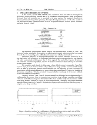
The paper discusses a droop control technique for achieving equal power sharing in islanded microgrids, specifically using a modified robust droop controller integrated with fuzzy logic for frequency control. The study aims to eliminate frequency sharing errors among parallel-connected inverters, ensuring stable operation at a reference frequency of 50 Hz. Simulation results demonstrate that the proposed controller effectively improves frequency stability and power sharing performance under inductive line impedance conditions.
![International Journal of Power Electronics and Drive System (IJPEDS)
Vol. 10, No. 1, March 2019, pp. 530~537
ISSN: 2088-8694, DOI: 10.11591/ijpeds.v10.i1.pp530-537 530
Journal homepage: http://iaescore.com/journals/index.php/IJPEDS
Droop control technique for equal power sharing in islanded
microgrid
A. W. N. Husna1
, M. A. Roslan2
, M. H. Mat3
1Centre of Excellent for Renewable Energy, School of Electrical Systems Engineering,
Universiti Malaysia Perlis, Malaysia
2School of Electrical Systems Engineering, Universiti Malaysia Perlis, Malaysia
3Centre for Diploma Studies, Universiti Malaysia Perlis, Malaysia
Article Info ABSTRACT
Article history:
Received Sep 17, 2018
Revised Nov 29, 2018
Accepted Dec 14, 2018
This paper presents a droop control technique for equal power sharing in
islanded microgrid. In this study, the proposed controller is based on the
frequency droop method, is applied to a robust droop controller in parallel
connected inverters. The previous robust droop controller deals with voltage
droop method. A modification has been formed against this controller by
adding a fuzzy logic controller with the frequency droop method. The only
sharing error which is concentrated in this paper is the error in sharing the
rated frequency among the inverters. By adapting fuzzy in the robust droop,
it tries to eliminate the frequency error, hence that the frequency reference of
the inverters keeps maintain at 50Hz. A derivation of generalized models of a
single-phase parallel-connected inverter system is shown. The simulation
results show that the proposed controller with FLC is able to improve the
stability of frequency reference and the performance of power sharing
between the inverters under the inductive line impedance.
Keywords:
Fuzzy control
Robust droop
Islanded microgrid
Parallel-connected inverters
Proportional load sharing
Frequency regulation
Reduction block
Copyright © 2019 Institute of Advanced Engineering and Science.
All rights reserved.
Corresponding Author:
A.W.N. Husna,
Centre of Excellent for Renewable Energy,
School of Electrical Systems Engineering, Universiti Malaysia Perlis,
Pauh Putra Campus, 02600 Arau, Perlis, Malaysia.
Email: nurulhusna.awb@gmail.comW
1. INTRODUCTION
Advanced development of distributed generation (DG) units in many countries nowadays has
attracted most researchers in all over the world due to the availability of different energy resources such as
photovoltaic panels, fuel cells, and wind turbines [1]. Through the concept of a microgrid which is the best
option to reduce a dependency on the local utility, consists of at least one DG, energy storage devices and
associated loads. Microgrid with two mode operations either in grid connected or islanded; has been
considered as one of the nominess to support smooth installation of DGs as the installation of many DGs
itself could be harmful to the power quality of utility power systems [2]–[4]. A details correlation between
microgrid and DG already discovered by Ping et al [5]. Basically, microgrid control in an islanded mode is
more complex than grid connected mode. The voltage and frequency of the microgrid are supported by the
main grid if in the grid connected mode. In contrast, the voltage and frequency control and even power
management process will be generated by DG units in islanded mode. The occurrence of power mismatch
between the DG and the load will lead to the unbalanced allowed value of the load voltage and frequency
deviation as well as unstable behaviours especially the existence of circulating current. Thus, it is necessary
to have a good controller to support voltage and frequency stability as well as suitable power sharing among
DG units in islanded mode operation [6].](https://image.slidesharecdn.com/5329nov1816897editnindi-210622024717/85/Droop-control-technique-for-equal-power-sharing-in-islanded-microgrid-1-320.jpg)
![International Journal of Power Electronics and Drive System (IJPEDS)
Vol. 10, No. 1, March 2019, pp. 530~537
ISSN: 2088-8694, DOI: 10.11591/ijpeds.v10.i1.pp530-537 530
Journal homepage: http://iaescore.com/journals/index.php/IJPEDS
Droop control technique for equal power sharing in islanded
microgrid
A. W. N. Husna1
, M. A. Roslan2
, M. H. Mat3
1Centre of Excellent for Renewable Energy, School of Electrical Systems Engineering,
Universiti Malaysia Perlis, Malaysia
2School of Electrical Systems Engineering, Universiti Malaysia Perlis, Malaysia
3Centre for Diploma Studies, Universiti Malaysia Perlis, Malaysia
Article Info ABSTRACT
Article history:
Received Sep 17, 2018
Revised Nov 29, 2018
Accepted Dec 14, 2018
This paper presents a droop control technique for equal power sharing in
islanded microgrid. In this study, the proposed controller is based on the
frequency droop method, is applied to a robust droop controller in parallel
connected inverters. The previous robust droop controller deals with voltage
droop method. A modification has been formed against this controller by
adding a fuzzy logic controller with the frequency droop method. The only
sharing error which is concentrated in this paper is the error in sharing the
rated frequency among the inverters. By adapting fuzzy in the robust droop,
it tries to eliminate the frequency error, hence that the frequency reference of
the inverters keeps maintain at 50Hz. A derivation of generalized models of a
single-phase parallel-connected inverter system is shown. The simulation
results show that the proposed controller with FLC is able to improve the
stability of frequency reference and the performance of power sharing
between the inverters under the inductive line impedance.
Keywords:
Fuzzy control
Robust droop
Islanded microgrid
Parallel-connected inverters
Proportional load sharing
Frequency regulation
Reduction block
Copyright © 2019 Institute of Advanced Engineering and Science.
All rights reserved.
Corresponding Author:
A.W.N. Husna,
Centre of Excellent for Renewable Energy,
School of Electrical Systems Engineering, Universiti Malaysia Perlis,
Pauh Putra Campus, 02600 Arau, Perlis, Malaysia.
Email: nurulhusna.awb@gmail.comW
1. INTRODUCTION
Advanced development of distributed generation (DG) units in many countries nowadays has
attracted most researchers in all over the world due to the availability of different energy resources such as
photovoltaic panels, fuel cells, and wind turbines [1]. Through the concept of a microgrid which is the best
option to reduce a dependency on the local utility, consists of at least one DG, energy storage devices and
associated loads. Microgrid with two mode operations either in grid connected or islanded; has been
considered as one of the nominess to support smooth installation of DGs as the installation of many DGs
itself could be harmful to the power quality of utility power systems [2]–[4]. A details correlation between
microgrid and DG already discovered by Ping et al [5]. Basically, microgrid control in an islanded mode is
more complex than grid connected mode. The voltage and frequency of the microgrid are supported by the
main grid if in the grid connected mode. In contrast, the voltage and frequency control and even power
management process will be generated by DG units in islanded mode. The occurrence of power mismatch
between the DG and the load will lead to the unbalanced allowed value of the load voltage and frequency
deviation as well as unstable behaviours especially the existence of circulating current. Thus, it is necessary
to have a good controller to support voltage and frequency stability as well as suitable power sharing among
DG units in islanded mode operation [6].](https://image.slidesharecdn.com/5329nov1816897editnindi-210622024717/75/Droop-control-technique-for-equal-power-sharing-in-islanded-microgrid-1-2048.jpg)
![Int J Pow Elec & Dri Syst ISSN: 2088-8694
Droop control technique for equal power sharing in islanded microgrid (A. W. N. Husna)
531
The essential objective of an islanded mode is to keep up precise power sharing among various DG.
Whenever the operation of microgrid shifted to island mode, electric potential, E and frequency, are
considered to be maintained with several inverters working in parallel and sharing the load. These inverters
act in regulating the voltage; amplitude and frequency, instead of different mode of operation like other
converter [7]; besides providing the required current needed. However, the issue of power quality [8] that
contributed by the existence of transient circulating current in line impedance [9] will lead to the system
instability, thus can harmful the inverters [10] due to mismatch of the output voltage. In an islanded
microgrid, loads must be properly shared by multiple DG units. Generally, the control techniques for parallel
operation of inverters in islanded microgrid operation can be split into two categories; droop control
techniques[11], [12] and active load sharing techniques [13], [14].
Droop control is the common control that widely used in microgrid due to no dependenment on
communication among parallel-connected inverters thus making it highly modular and reliable [15]–[17]. It
is applicable when two or more inverters are applied. Generally, it detects the output power as a feedback
parameter while the deviation of DC voltage is controlled in proportion to the output power. Typically, the
voltage droop control results in poor reactive power sharing whilst the frequency droop control always
achieves accurate real power sharing. It is due to the different offsets of local loads as well as the mismatch
in feeder impedances.
This paper seeks to expand the method of robust droop presented in [18] by adapted with frequency
control instead of the voltage control using fuzzy logic control (FLC). It will retain the frequency reference of
50 Hz in parallel-connected inverters using inductive line impedance. The control approach presented by the
previous author applied Q− and P −E droop to the resistive line impedance with switching action of pulse-
width modulation (PWM) to improve the strategy that works for grid-connected applications via adding a
unit to regulate the load voltage. In this work, an FLC is adjusted to the robust control by putting through the
frequency droop precisely integrated in Q− . Practically, the operation of the controller is robust against
load perturbation and even an emergency circumstance such as disconnection of DG unit and the proposed
controller is actually being designed for frequency control indeed. The parallel-connected inverters
incorporate with a proportional-resonant controller (PR) and sinusoidal pulse-width modulation (SPWM)
instead of proportional-integral (PI) and PWM in the islanded microgrid. Various simulations have been
taken out to verify and analysis the capability of the proposed controller against the robust droop controller.
2. SYSTEM CONFIGURATION OF PARALLEL-CONNECTED INVERTER
In this section will explain in details of construction of single-phase full-bridge inverter and the
parallel-connected inverters used in the simulation.
2.1. Model of single-phase inverter
The single-phase inverter is an electronic circuit that enables a voltage to be applied across a load in
either direction. It can be simplified justified with a switching scheme of full-bridge converter. Typically, it
consists of a DC power source, and a bridge-type inverter with LCL filter as shown in Figure 1. The inverter
is a device which converts a DC input supply voltage into symmetrical AC voltage based on the modulation
signal from the SPWM modulation. The inductance, resistance, and capacitance are represented by Lf, Rf, and
Cf. The line impedance represented Rline and Lline between the inverter and the load is the equivalent
impedance due to connecting lines or cables.
Figure 1. Block diagram of an inverter
2.2. Parallel-connected inverter
Three parallel-connected inverters are used to fill in the microgrid configuration as depicted in
Figure 2. The model of parallel-connected inverters is a necessary in order to apply droop method in the
system. Previously, a conventional PI controller is used with the voltage feedback loop [13] to regulate the](https://image.slidesharecdn.com/5329nov1816897editnindi-210622024717/85/Droop-control-technique-for-equal-power-sharing-in-islanded-microgrid-2-320.jpg)
![ ISSN: 2088-8694
Int J Pow Elec & Dri Syst, Vol. 10, No. 1, March 2019 : 530 – 537
532
ouput voltage. Therefore, it is sensible to used PR controller instead of PI controller due to its superior
performance in terms of less steady-state error, good dynamic response, as well as its capability in reducing
steady-state deviation of frequency and amplitude [19]. In order to ensure in-phase similarity of the output
voltage of each inverter, the same voltage reference is used, 0
V
. PR controller gain the feedback values of
output voltage and current from the inverter, thus, generate a proper controlled signal before transmitted to
SPWM. Then, SPWM used to put through the switching process and pass a practical condition of the
microgrid. The active and reactive power of each inverter is obtained based on the voltage and current
measurement after filtering, later will be fed to the proposed controller block to produce new value of
reference voltage, Vref and angular frequency, i
which will be led to proportional power sharing.
Load
PR SPWM
+
-
Vo iref
+
-
+
+ Vo
Droop Control
Voltage
Controller
Inverter
Io
IL
PR SPWM
+
-
Vo iref
+
-
+
+ Vo
Droop Control
Voltage
Controller
Inverter
Io
IL
PR SPWM
+
-
Vo iref
+
-
+
+ Vo
Droop Control
Voltage
Controller
Inverter
Io
IL
Figure 2. Parallel-connected inverters in microgrid configuration
3. CONTROL SCHEME
3.1. Robust droop control
As presented in [18], the quantitative analysis of the error in power sharing has been carried out by
the author. From the paper, the sharing error which is from the error in measuring the load voltage is carried
out to adapt to the robust droop method. In practice, when there are errors in the voltage measured, a
fundamental tradeoff between the voltage drop and the sharing accuracy appears thus will lead to the errors
in proportional load sharing. Unsimilar with the conventional droop control, the author proposed a robust
droop controller by implementing Q−ω and P −E droop analysis and RMS voltage set-points for the
inverters through voltage droop. In order to make sure that the voltage remains within a certain required
range, the load voltage drop E*−Vo needs to be fed back in a certain way, according to the basic principles of
control theory. It can be added to ∆Ei via an amplifier, Ke and resulted the robust controller as indicated in
Figure 3 (a). This control scheme is a benchmarking to the proposed controller in this paper. However, in this
paper will be focusing on the frequency regulation; using the frequency droop. Therefore, the frequency
droop will be replacing the voltage droop method by modifying the equation of robust droop controller (1).
However, the possibility of measured frequency to remain within a certain required range in the parallel-
connected inverters usually are quite unmanageable and will conduct in contributing of error value.
sin( )
ref
V E t
(1)
In establishing the parallel-connected inverters enable to share the load, the representation of the
conventional droop controller in (2) and (3) are used. The angular frequency, ωi is widely utilized to generate
the frequency of the frequency reference for the inverters, where ω*
is the rated frequency and mi is a
droop coefficient.](https://image.slidesharecdn.com/5329nov1816897editnindi-210622024717/85/Droop-control-technique-for-equal-power-sharing-in-islanded-microgrid-3-320.jpg)
![Int J Pow Elec & Dri Syst ISSN: 2088-8694
Droop control technique for equal power sharing in islanded microgrid (A. W. N. Husna)
533
*
i i i
E E n P
(2)
*
i i i
m Q
(3)
From (3), the representation of the frequency droop control can be written as
*
i i i i
m Q
(4)
and the frequency ωi can be implemented via integrating Δωi as
0
t
i idt
(5)
ni
mi
1/s
Vref
E
ω t+δ
ω *
-
Q
P
i
vo
RMS
Ke
E*
-
ni
mi
1/s
Vref
E
ω t+δ
ω *
-
Q
P
i
vo
RMS
Ke
E*
-
Freq*
e
de
Gain
+
(a) (b)
Figure 3. Control scheme (a) Robust droop (b) Robust droop with FLC
3.2. FLC-based robust droop control
In order to improve the as mentioned controller in the previous section, some changes have been
made to realize it. Regarding to the proposed controller, the concept and modeling of the basic robust droop
controller are already highlighted in [18]. In this paper, FLC method is implemented based on frequency
error, rr
e of each inverter. The voltage reference, Vref and new frequency reference (based on the per unit of
output voltage) of voltage control unit is brought out by the frequency control unit as indicated in Figure 3
(b). The initiation of the frequency control unit is droop method. Previously, conventional droop control has
been used as voltage and frequency regulation and even power sharing process among DG units. In this
method, instantaneous active and reactive power components are received from the local measured of current
and voltage. Then, they are passed through a low pass filter with cutoff frequency, c
.
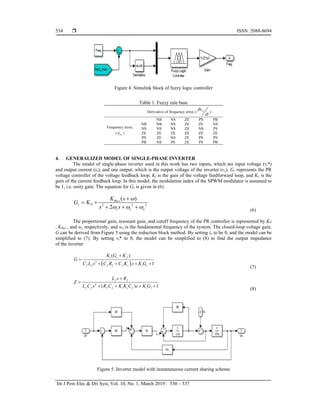
As illustrated in Figure 4, FLC with unity feedback is implemented with robust droop control. The
new reference frequency is the output of fuzzy system with respect to two inputs of frequency error (err) and
its derivative ( rr
de
dt
). The membership function for both input and output are considered to work with
triangular membership function. The applied rules are as in Table 1.](https://image.slidesharecdn.com/5329nov1816897editnindi-210622024717/85/Droop-control-technique-for-equal-power-sharing-in-islanded-microgrid-4-320.jpg)
![Int J Pow Elec & Dri Syst ISSN: 2088-8694
Droop control technique for equal power sharing in islanded microgrid (A. W. N. Husna)
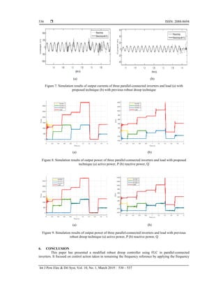
537
droop method. A simplified model of single-phase inverter is used to investigate system stability in terms of
output current and voltage. The rules of FLC are tuned to deal with the error and change of error of frequency
of the system. According to the results above, the proposed control strategy is able to provide a stable angular
frequency for microgrids working in the islanded mode. The limited scope of the previous robust droop
controller that analyzed with voltage droop has been noticed. Meanwhile, the proposed controller has proven
that it is capable of outperforming the lacks of the robust droop controller in providing a smooth and stable in
line response. Additionally, with less overshoot in response and dependable in a line perturbation show that
the proposed controller achieves good performance in system response with less circulating current as well as
better power sharing.
REFERENCES
[1] A. W. N. Husna, S. F. Siraj, and M. Z. Ab Muin, “Modeling of DC-DC converter for solar energy system
applications,” in 2012 IEEE Symposium on Computers and Informatics, ISCI 2012, 2012.
[2] T. Hornik and Q.-C. Zhong, “A Current-Control Strategy for Voltage-Source Inverters in Microgrids Based on
$H^{infty }$ and Repetitive Control,” IEEE Trans. Power Electron., vol. 26, no. 3, pp. 943–952, Mar. 2011.
[3] P. Tenti, H. K. M. Paredes, and P. Mattavelli, “Conservative Power Theory, a Framework to Approach Control and
Accountability Issues in Smart Microgrids,” IEEE Trans. Power Electron., vol. 26, no. 3, pp. 664–673, Mar. 2011.
[4] J. Rocabert, G. M. S. Azevedo, A. Luna, J. M. Guerrero, J. I. Candela, and P. Rodríguez, “Intelligent Connection
Agent for Three-Phase Grid-Connected Microgrids,” IEEE Trans. Power Electron., vol. 26, no. 10,
pp. 2993–3005, Oct. 2011.
[5] P. Ji, X. X. Zhou, and S. Wu, “Review on sustainable development of island microgrid,” in 2011 International
Conference on Advanced Power System Automation and Protection, 2011, pp. 1806–1813.
[6] M. S. Sadabadi, Q. Shafiee, and A. Karimi, “Plug-and-Play Voltage Stabilization in Inverter-Interfaced Microgrids
via a Robust Control Strategy,” IEEE Trans. Control Syst. Technol., vol. 25, no. 3, pp. 781–791, May 2017.
[7] A. W. N. Husna, S. F. Siraj, and M. H. Mat, “Effect of load variations in DC-DC converter,” in Proceedings -
CIMSim 2011: 3rd International Conference on Computational Intelligence, Modelling and Simulation, 2011.
[8] N. Bottrell, M. Prodanovic, and T. C. Green, “Dynamic Stability of a Microgrid With an Active Load,” IEEE
Trans. Power Electron., vol. 28, no. 11, pp. 5107–5119, Nov. 2013.
[9] M. A. Roslan, M. S. Ahmad, M. A. M. Isa, and N. H. A. Rahman, “Circulating current in parallel connected
inverter system,” in 2016 IEEE International Conference on Power and Energy (PECon), 2016, pp. 172–177.
[10] A. Vijayakumari, A. T. Devarajan, and N. Devarajan, “Decoupled control of grid connected inverter with dynamic
online grid impedance measurements for micro grid applications,” Int. J. Electr. Power Energy Syst., vol. 68,
pp. 1–14, Jun. 2015.
[11] M. R. Miveh, M. F. Rahmat, A. A. Ghadimi, and M. W. Mustafa, “Control techniques for three-phase four-leg
voltage source inverters in autonomous microgrids: A review,” Renew. Sustain. Energy Rev., vol. 54,
pp. 1592–1610, 2016.
[12] N. H. A. Wahab, M. H. Mat, and M. A. Roslan, “A Review on Optimization of Control Strategy on Paralleled
Connected Inverters in an Islanded Microgrid,” Adv. Sci. Lett., vol. 23, no. 6, pp. 5406–5409, Jun. 2017.
[13] P. Monica, M. Kowsalya, and P. C. Tejaswi, “Load sharing control of parallel operated single phase inverters,”
Energy Procedia, vol. 117, pp. 600–606, 2017.
[14] P. Sreekumar and V. Khadkikar, “Nonlinear load sharing in low voltage microgrid using negative virtual harmonic
impedance,” IECON 2015 - 41st Annu. Conf. IEEE Ind. Electron. Soc., no. 1, pp. 3353–3358, 2015.
[15] Institute of Electrical and Electronics Engineers. and IEEE-SA Standards Board., IEEE guide for design, operation,
and integration of distributed resource island systems with electric power systems. Institute of Electrical and
Electronics Engineers, 2011.
[16] Y. Mohamed and E. F. El-Saadany, “Adaptive Decentralized Droop Controller to Preserve Power Sharing Stability
of Paralleled Inverters in Distributed Generation Microgrids,” IEEE Trans. Power Electron., vol. 23, no. 6,
pp. 2806–2816, Nov. 2008.
[17] A. M. Bouzid, J. M. Guerrero, A. Cheriti, M. Bouhamida, P. Sicard, and M. Benghanem, “A survey on control of
electric power distributed generation systems for microgrid applications,” Renew. Sustain. Energy Rev., vol. 44,
pp. 751–766, 2015.
[18] Q. C. Zhong, “Robust droop controller for accurate proportional load sharing among inverters operated in parallel,”
IEEE Trans. Ind. Electron., vol. 60, no. 4, pp. 1281–1290, 2013.
[19] A. Hasanzadeh, O. C. Onar, H. Mokhtari, and A. Khaligh, “A Proportional-Resonant Controller-Based Wireless
Control Strategy With a Reduced Number of Sensors for Parallel-Operated UPSs,” IEEE Trans. Power Deliv., vol.
25, no. 1, pp. 468–478, Jan. 2010.](https://image.slidesharecdn.com/5329nov1816897editnindi-210622024717/85/Droop-control-technique-for-equal-power-sharing-in-islanded-microgrid-8-320.jpg)