Downloaded 12 times
![IJRET: International Journal of Research in Engineering and Technology eISSN: 2319-1163 | pISSN: 2321-7308
__________________________________________________________________________________________
Volume: 03 Special Issue: 07 | May-2014, Available @ http://www.ijret.org 598
PERFORMANCE ANALYSIS OF AUTONOMOUS MICROGRID SUBSEQUENT TO LINE - GROUND FAULT TRIGGERED CONDITION N. Chitra1, A. Senthil Kumar2, K.M. Shobana3 Abstract With the emergent expansion of micro grid, the performances of microgrid subsequent to the various fault conditions have become an attractive area to be examined. This paper investigates the dynamic performance of the microgrid during (i) addition of non-linear load and (ii) fault triggered events. The microgrid consists of two DGs which are interfaced through a PE converter. The interface converters are equipped with P-F and Q-V droop control. The impacts of the droop control on the microgrid stability has been analysed in this work. The performance of the controllers in MATLAB/SIMULINK platform is also presented. Keywords— Distributed Generation, Droop control, L-G Fault, Microgrid, Non-linear load
---------------------------------------------------------------------***------------------------------------------------------------------------- 1. INTRODUCTION WITH the Growing importance of clean energy technology and the interactions of power electronic devices with the renewable energy sources, the distribution network adapted a new concept of ―microgrids.‖ Distributed generation (DG), micro sources, controllers, loads and storage devices are composed together to form a microgrid structure [1]. Microsources like diesel genera- tor, fuel cells, solar cells, and wind turbine generator are used in microgrid [2]. DGs are commonly paired with the power elec- tronic devices like inverters to make in contact with the micro- grid. It supports the main grid by providing the reliable power supply independently without the requirement of generation expansion [1]. A microgrid system can function in two sorts based on the static transfer switch (STS) position namely, grid tied mode and auto- nomous mode. When a fault or any disturbances occurs, the microgrid automatically shifts to the isolated mode i.e., island mode. It is necessary for a microgrid to function even in iso- lated mode in order to maintain the load demand, power supply reliability and power quality [3]. Therefore, the problem related with enhancing the microgrid dynamic response to the un- planned events gathers attention [4]. In the existing scenario, the power companies face a tough competition in order to enhance the quality and reliability of never-ending power supply. Therefore it is more imperative to tackle the DG disconnection due to intentional or accidental events. In course of island function of microgrid, the DG has to sense instantly and switch over to the control modes, so that voltage is supplied uninterruptedly to the sensitive loads. [5]
In current scenario, the custom of the utility do not authorise the microgrid to function in an island mode. But it will permit in exceptional circumstances, which desperately need all the DGs to be detached when scheduled and accidental switching transients exist. The above mentioned criterion is applied on the basis of safety purpose and also to satisfy the present protection constraints in the distribution system. [6] During transition from grid connected mode to island mode, there is a possibility of microgrid to experience transient stabili- ty problem. This situation particularly occurs when the microgr- id is unable to satisfy the load demand due to system’s rotating kinetic energy reduces. Even though the micro sources are interfaced with power elec- tronic devices, but it is highly vulnerable to the transient over- loads. So it is obligatory to spot the transient instability and small signal instability [2]. Typically the microgrid is functioned parallel to the main grid but at the event of fault conditions it gets detached from the main grid and functioned independently. The most challenging subject in the microgrid is protection against the fault events [7]. The protection of microgrid relates with the issues of con- trol and operation of a microgrid.Among various control schemes, this paper highlight on droop control techniques like P-F droop control & Q-V droop control.
The primary focus of droop control is to retain the fundamental frequency & the voltage magnitude of microgrid with manifold DGs in autonomous mode so that the appropriate powers are shared [8]. Frequently used droop control technique to enhance power sharing and the voltage/ frequency synchronization are real power–frequency (P–F) droop control and reactive power– voltage magnitude (Q–V) droop control. Consequently its im- plementation is simple and it empowers decentralized control of](https://image.slidesharecdn.com/performanceanalysisofautonomousmicrogrid-140826223603-phpapp01/75/Performance-analysis-of-autonomous-microgrid-1-2048.jpg)
![IJRET: International Journal of Research in Engineering and Technology eISSN: 2319-1163 | pISSN: 2321-7308
__________________________________________________________________________________________
Volume: 03 Special Issue: 07 | May-2014, Available @ http://www.ijret.org 599
manifold distributed generations (DGs) It has been shown that inverter interfaced DG can damp fre- quency oscillations through it has fast control action. For the inverter-based DG, a control scheme based on the real/reactive power control concept is considered. This paper analyses the impact of different control approaches and schemes of an inver- ter-based DG on microgrid stability during and subsequent to fault-forced islanding conditions. Further, the microgrid stabili- ty performance is examined with different load types, IM loads. The significant contributions of this work include: 1) Cataloguing of the stability constraints for an inverter based generators and inverter coupled DG interface control schemes. 2) Investigation of the interface constraint of induction motor loads and DG on a microgrid subsequent to fault activated is- landing incidents. 2. CONTROL STRATEGIES The frequency and the active power are merely interrelated foe a generators. As the load increases, the load torque increase correspondingly which earns that the rotational speed and the system frequency to decrease [8]. The decreasing frequency with increasing load is maintained by the concept of droop con- trol. The control strategy used in this work is conventional droop control i.e., real power- frequency droop control (P-F) and reactive power – voltage droop control (Q-V). The frequency and voltage are being controlled respectively by the active and reactive power output of the DG sources. Thus the distributed power sharing in microgrid is based on maintain- ing the power output proportionally according to the DGs rating and power sharing among DGs [9]. 2.1 P-F Droop Control Method In a P-F droop control method, all DG in the system utilise its real power output and fix the frequency at its point of connec- tion (PC). So in order to share real power accurately, the fre- quency will perform as the common communication signal among all the DGs [8]. When the microgrid is switched to isl- and mode, each inverter experiences an error in the frequency generation. To resolve this, operating points of the power is altered to match the load. P-F droop functions at each micro- source can effectually resolve these difficulties without a com- munication linkage. During grid attached mode, the loads acquire power from the grid and the main power supply as per the utility requirement the microgrids safely switch over to the isolate mode in case of non-availability of main power supply due to fault, voltage transient, black outs, etc [9],[10]. During isolated mode, phase angle of the voltage at each DG will alter which results in nota- ble frequency reduction. In addition to this frequency reduction, the increase in power permits accurate power sharing at each DG.
2.2 Q-V Droop Control
The output voltage magnitude of a DG can be controlled to change the reactive power supplied to a system. However, in the presence of a number of DGs, maintaining a voltage to a pre-defined value can cause the reactive power circulation amongst these DGs. This becomes more prevalent when the microgrid has short line segments. This problem can be mini- mized by implementing voltage droop control in all the DGs [11]. Also, the voltage droop control results in reactive load power sharing in the microgrid. The conventional voltage droop characteristic. Voltage control must also insure that there are no large circulat- ing reactive currents between sources. With small errors in vol- tage set points, the circulating current can exceed the ratings of the microsources. This situation requires a voltage vs. reactive power droop con- troller so that, as the reactive power generated by the micro- source becomes more capacitive, the local voltage set point is reduced. Conversely, as Q becomes more inductive, the voltage set point is increased [12]. The relationship between P-f & Q-V droop control is f = f0 – Kp (P – P0) V = V0 – Kq (Q – Q0) Where, f, V = The frequency and Voltage at a new operating point P, Q = Active and reactive power at a new operating point f0 , V0 = Base frequency and voltage P0 , Q0 = temporary set points for the real and reactive power. Kp , Kq = UPC droop constant 3. STABILITY ANALYSIS Recently in the stream of microgrid, the stability analysis gains more importance on the researchers’ perception. The system planners and operators are primarily focusing on the reclama- tion of the power system when exposed to a severe disturbance. Classically the system must be planned and operated by con- cerning the uninterruptable power supply to the loads. Transient stability exploration can also be used for the dynamic analysis over time duration of few seconds toward few minutes based on the time constants of dynamic modeled[13],[14].](https://image.slidesharecdn.com/performanceanalysisofautonomousmicrogrid-140826223603-phpapp01/75/Performance-analysis-of-autonomous-microgrid-2-2048.jpg)
![IJRET: International Journal of Research in Engineering and Technology eISSN: 2319-1163 | pISSN: 2321-7308
__________________________________________________________________________________________
Volume: 03 Special Issue: 07 | May-2014, Available @ http://www.ijret.org 600
Fig 3.1 Different stability issues in microgrid 3.1 Transient Stability The microgrid is capable of functioning even after large distur- bances, which is the system will shift its functioning mode to island mode. The large disturbance occurs because of the switching of heavy loads suddenly, faults that occur on the transmission line, generating units tripping. This sudden distur- bance makes the system to lose its synchronism. This sort of stability is designated as transient stability. The system stability issues have been explored by the many researchers recently [15]. Various stability issues and the stability improvement me- thods are shown in Fig 3.1 and Fig 3.2. The stability aspect in- cludes the types of microgrid, micro sources, its parameters and control strategies. Since most of the micro sources are inter coupled with the power electronic devices i.e. voltage source inverter (VSI), the stability aspects of the microgrid mainly based on the control methods of the VSI [16],[17]. 3.2 L-G Fault The L-G faults are detected by the zero sequence current which is manipulated from the three phase current.In a fault, the sys- tem may lose stability very rapidly before the loads are cut off [18]. In a microgrid, storage plays an important role during is- landing. F
A
RF
G
B
C Fig 2 Single Line to Ground fault
Single line to ground fault is explored in this work. The fault is occurring at the phase A to ground as shown in the Fig 2.
4. SIMULATION MODEL
The microgrid is modelled with two micro sources which have a DC source as input and the P-F and Q-V droop control have been employed. At the time of starting, RL load is connected to the system as shown in Fig 3. In order to highlight the perfor- mance difference of microgrid when connected with normal load and nonlinear load, induction motor is connected at 0.75sec and disconnected at 2.5 sec. As a next, study about the activity of microgrid with RL load during fault triggered inci- dent for a period of analysed. To perform this activity, a LG fault was introduced for a period of 1 to 1.5 secs. This microgr- id system has been simulated under the Matlab/Simulink soft- ware environs.
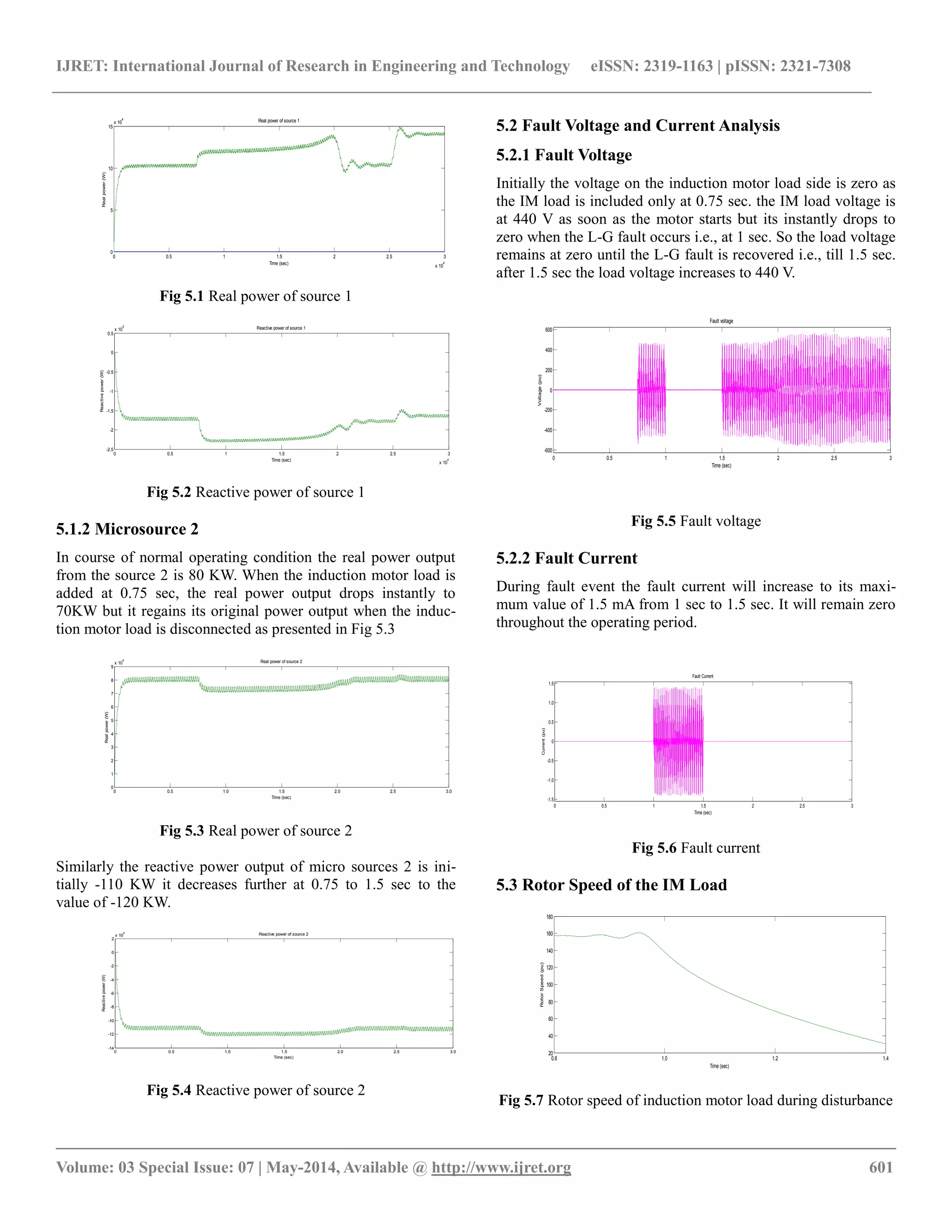
Fig 3 Single line layout of the utility and microgrid systems 5. SIMULATION RESULTS The simulation result includes real and reactive power of DG1 and DG2 respectively. Fault voltage, fault current and rotor speed of induction motor load is also analysed during the dis- turbance period. 5.1 Real and Reactive Power 5.1.1 Microsource 1 The simulation starts with RL load at 0.75 sec induction motor load is added so that the real power of source 1 increases from 100KW to 110KW whereas the reactive power of source 1 de- creases from -180KW to -240KW as cited in Fig 5.1 and Fig 5.2. At 2.5 sec the induction motor load is disconnected from the grid. So that the real and reactive power regains its original power output. As it is on the source side, the real and reactive power of the microsources does not affect because of the L-G fault.](https://image.slidesharecdn.com/performanceanalysisofautonomousmicrogrid-140826223603-phpapp01/75/Performance-analysis-of-autonomous-microgrid-3-2048.jpg)
![IJRET: International Journal of Research in Engineering and Technology eISSN: 2319-1163 | pISSN: 2321-7308
__________________________________________________________________________________________
Volume: 03 Special Issue: 07 | May-2014, Available @ http://www.ijret.org 602
Before fault, the rotor rotates at a rated speed. During L-G fault event, it is observable that the rotor speed drops to zero from its rated speed. So from 1 sec to 1.5 sec the IM load will starts to shut down. The rotor speed response of the IM load to the disturbance is exposed in Fig 5.7. During disturbance period the torque imbalance will occur so that the rotor speed suddenly reduces. 6. CONCLUSIONS In this paper, based on droop control scheme, which includes P- F and Q-V droop control is studied for microgrid stability. The proposed control scheme is demonstrated for a microgrid with two inverter interfaced DG units. This paper evaluates the im- pact of P-F and Q-V droop control strategies of microgrid under load change and subsequent to the fault incident. The impacts identified are 1. Load power is shared equally for inverter interfaced DG with P-F and Q-V droop control. 2. There is a voltage dip due to the IM load. 3. Due to the occurrence of the L-G fault , the microgrids switch over from grid-tied mode to island mode. REFERENCES
[1] J.S. Bridle, ―Probabilistic Interpretation of Feedforward Classification Network Outputs, with Relationships to Statistical Pattern Recognition,‖ Neurocomputing— Algorithms, Architectures and Applications, F. Fogel- man-Soulie and J. Herault, eds., NATO ASI Series F68, Berlin: Springer-Verlag, pp. 227-236, 1989. (Book style with paper title and editor)
[2] W.-K. Chen, Linear Networks and Systems. Belmont, Calif.: Wadsworth, pp. 123-135, 1993. (Book style)
[3] H. Poor, ―A Hypertext History of Multiuser Dimen- sions,‖ MUD History, http://www.ccs.neu.edu/home/pb/mud-history.html. 1986. (URL link *include year)
[4] K. Elissa, ―An Overview of Decision Theory," unpub- lished. (Unplublished manuscript)
[5] R. Nicole, "The Last Word on Decision Theory," J. Computer Vision, submitted for publication. (Pending publication)
[6] C. J. Kaufman, Rocky Mountain Research Laboratories, Boulder, Colo., personal communication, 1992. (Person- al communication)
[7] D.S. Coming and O.G. Staadt, "Velocity-Aligned Dis- crete Oriented Polytopes for Dynamic Collision Detec- tion," IEEE Trans. Visualization and Computer Graph- ics, vol. 14, no. 1, pp. 1-12, Jan/Feb 2008, doi:10.1109/TVCG.2007.70405. (IEEE Transactions )
[8] S.P. Bingulac, ―On the Compatibility of Adaptive Con- trollers,‖ Proc. Fourth Ann. Allerton Conf. Circuits and Systems Theory, pp. 8-16, 1994. (Conference proceed- ings)
[9] H. Goto, Y. Hasegawa, and M. Tanaka, ―Efficient Sche- duling Focusing on the Duality of MPL Representation,‖
Proc. IEEE Symp. Computational Intelligence in Sche- duling (SCIS ’07), pp. 57-64, Apr. 2007, doi:10.1109/SCIS.2007.367670. (Conference proceed- ings)
[10] J. Williams, ―Narrow-Band Analyzer,‖ PhD dissertation, Dept. of Electrical Eng., Harvard Univ., Cambridge, Mass., 1993. (Thesis or dissertation)
[11] E.E. Reber, R.L. Michell, and C.J. Carter, ―Oxygen Ab- sorption in the Earth’s Atmosphere,‖ Technical Report TR-0200 (420-46)-3, Aerospace Corp., Los Angeles, Ca- lif., Nov. 1988. (Technical report with report number)
[12] L. Hubert and P. Arabie, ―Comparing Partitions,‖ J. Classification, vol. 2, no. 4, pp. 193-218, Apr. 1985. (Journal or magazine citation)
[13] R.J. Vidmar, ―On the Use of Atmospheric Plasmas as Electromagnetic Reflectors,‖ IEEE Trans. Plasma Science, vol. 21, no. 3, pp. 876-880, available at http://www.halcyon.com/pub/journals/21ps03-vidmar, Aug. 1992. (URL for Transaction, journal, or magzine)
[14] J.M.P. Martinez, R.B. Llavori, M.J.A. Cabo, and T.B. Pedersen, "Integrating Data Warehouses with Web Data: A Survey," IEEE Trans. Knowledge and Data Eng., pre- print, 21 Dec. 2007, doi:10.1109/TKDE.2007.190746.(PrePrint)](https://image.slidesharecdn.com/performanceanalysisofautonomousmicrogrid-140826223603-phpapp01/75/Performance-analysis-of-autonomous-microgrid-5-2048.jpg)

This paper investigates the dynamic performance of microgrids under various fault conditions, specifically focusing on the impacts of droop control techniques on stability. It emphasizes the necessity for microgrids to maintain functionality in island mode during faults and analyzes the performance of controllers via MATLAB/Simulink simulations. Key findings include the behavior of microgrid stability during fault-triggered incidents, particularly the effects of adding non-linear loads and the management of real/reactive power in response to disturbances.


![ANPARA THERMAL POWER STATION[1] sangam.pdf](https://cdn.slidesharecdn.com/ss_thumbnails/anparathermalpowerstation1sangam-251121115219-9261cde4-thumbnail.jpg?width=640&height=640&fit=bounds)


