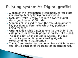
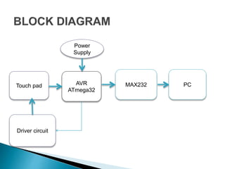
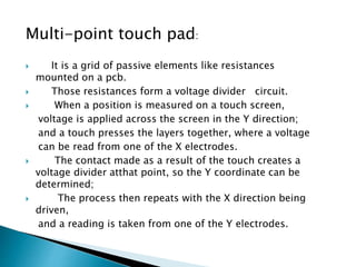
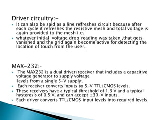
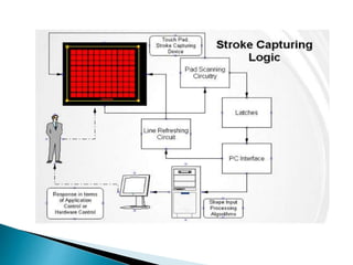
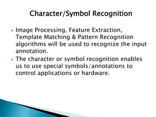
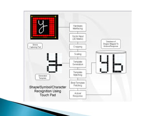
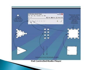
PRESENTED BY:-
 ARUNAVA PAUL
 VIJAYKUMAR KULKARNI
 VIVEKANAND DHAVALE
GUIDED BY:-
PROF-V.N.GHODKE
 Alphanumeric information is commonly entered into
microcomputers by typing on a keyboard .
 Each key stroke is converted into a coded digital
signal ,such as an ASCII code .
 Scanning ckt is used to scan the rows & columns of
key positions to determine which key position is
being touched.
 Writing pads enable a user to enter a sketch into the
data processor by “writing” on the surface of the pad.
 As each point on the sketch is written , the pad
senses its location & delivers analog signals
corresponding to that location .
 The A/D conversion can be done , from which the two
coordinate position of the point can be determined.
• Compatible for any computers
• Options selection with help of touch pad
• High accuracy and convenience
• To point out the exact location of the touch
 Research in the field of human computer
interaction has led to development of some
really smart devices to interface the computer
devices like touch screen, touch pad and
recently multipoint touch screen are result of
that.
 These new ways of interaction has also led
to development of some really dynamic
application & the aim of our project is to
propose a design of a touch pad for
dedicated customized applications.
Touch pad AVR
ATmega32
MAX232 PC
Power
Supply
Driver circuit
Multi-point touch pad:
 It is a grid of passive elements like resistances
mounted on a pcb.
 Those resistances form a voltage divider circuit.
 When a position is measured on a touch screen,
voltage is applied across the screen in the Y direction;
and a touch presses the layers together, where a voltage
can be read from one of the X electrodes.
 The contact made as a result of the touch creates a
voltage divider atthat point, so the Y coordinate can be
determined;
 The process then repeats with the X direction being
driven,
and a reading is taken from one of the Y electrodes.
 High-performance, Low-power AVR® 8-bit
Microcontroller
 32K Bytes of In-System Self-programmable Flash
program memory
 1024 Bytes EEPROM
 2K Byte Internal SRAM
 8-channel, 10-bit ADC
 Write/Erase Cycles: 10,000 Flash/100,000 EEPROM
 I/O and Packages
Driver circuitry:-
 It can also be said as a line refreshes circuit because after
each cycle it refreshes the resistive mesh and total voltage is
again provided to the mesh i.e.
 whatever initial voltage drop reading was taken ,that gets
vanished and the grid again become active for detecting the
location of touch from the user.
MAX-232:-
 The MAX232 is a dual driver/receiver that includes a capacitive
voltage generator to supply voltage
levels from a single 5-V supply.
 Each receiver converts inputs to 5-V TTL/CMOS levels.
 These receivers have a typical threshold of 1.3 V and a typical
hysteresis of 0.5 V, and can accept ±30-V inputs.
 Each driver converts TTL/CMOS input levels into required levels.
Character/Symbol Recognition
 Image Processing, Feature Extraction,
Template Matching & Pattern Recognition
algorithms will be used to recognize the input
annotation.
 The character or symbol recognition enables
us to use special symbols/annotations to
control applications or hardware.
• For conveying the message at public places like
bus stop , railway station.
• To control interactive gaming application
• To access an application software like ms-paint
• High reliability and performance ,low cost .
• Always a facility of upgradation.
• Performance per unit cost is good.
• Easiest way to interface with computer.
• VISUAL BASIC 6.0
• AVR STUDIO
• ORCAD
 Visual Object Recognition using Template
Matching (http:/ / www. araa. asn. au/ acra/
acra2004/ papers/ cole.pdf)
 http://en.wikipedia.org/w/index.php?title=Fe
ature_detection_%28 computer_vision%29
 www.datasheetcatalog.com
 Programming and customizing the AVR
microcontroller-D.V.Gadre
 http://www.senet.com.au/~cpeacock
THANK YOU…..

Digital Graffiti

  • 1.
    PRESENTED BY:-  ARUNAVAPAUL  VIJAYKUMAR KULKARNI  VIVEKANAND DHAVALE GUIDED BY:- PROF-V.N.GHODKE
  • 2.
     Alphanumeric informationis commonly entered into microcomputers by typing on a keyboard .  Each key stroke is converted into a coded digital signal ,such as an ASCII code .  Scanning ckt is used to scan the rows & columns of key positions to determine which key position is being touched.  Writing pads enable a user to enter a sketch into the data processor by “writing” on the surface of the pad.  As each point on the sketch is written , the pad senses its location & delivers analog signals corresponding to that location .  The A/D conversion can be done , from which the two coordinate position of the point can be determined.
  • 3.
    • Compatible forany computers • Options selection with help of touch pad • High accuracy and convenience • To point out the exact location of the touch
  • 4.
     Research inthe field of human computer interaction has led to development of some really smart devices to interface the computer devices like touch screen, touch pad and recently multipoint touch screen are result of that.  These new ways of interaction has also led to development of some really dynamic application & the aim of our project is to propose a design of a touch pad for dedicated customized applications.
  • 5.
    Touch pad AVR ATmega32 MAX232PC Power Supply Driver circuit
  • 6.
    Multi-point touch pad: It is a grid of passive elements like resistances mounted on a pcb.  Those resistances form a voltage divider circuit.  When a position is measured on a touch screen, voltage is applied across the screen in the Y direction; and a touch presses the layers together, where a voltage can be read from one of the X electrodes.  The contact made as a result of the touch creates a voltage divider atthat point, so the Y coordinate can be determined;  The process then repeats with the X direction being driven, and a reading is taken from one of the Y electrodes.
  • 7.
     High-performance, Low-powerAVR® 8-bit Microcontroller  32K Bytes of In-System Self-programmable Flash program memory  1024 Bytes EEPROM  2K Byte Internal SRAM  8-channel, 10-bit ADC  Write/Erase Cycles: 10,000 Flash/100,000 EEPROM  I/O and Packages
  • 8.
    Driver circuitry:-  Itcan also be said as a line refreshes circuit because after each cycle it refreshes the resistive mesh and total voltage is again provided to the mesh i.e.  whatever initial voltage drop reading was taken ,that gets vanished and the grid again become active for detecting the location of touch from the user. MAX-232:-  The MAX232 is a dual driver/receiver that includes a capacitive voltage generator to supply voltage levels from a single 5-V supply.  Each receiver converts inputs to 5-V TTL/CMOS levels.  These receivers have a typical threshold of 1.3 V and a typical hysteresis of 0.5 V, and can accept ±30-V inputs.  Each driver converts TTL/CMOS input levels into required levels.
  • 10.
    Character/Symbol Recognition  ImageProcessing, Feature Extraction, Template Matching & Pattern Recognition algorithms will be used to recognize the input annotation.  The character or symbol recognition enables us to use special symbols/annotations to control applications or hardware.
  • 12.
    • For conveyingthe message at public places like bus stop , railway station. • To control interactive gaming application • To access an application software like ms-paint
  • 14.
    • High reliabilityand performance ,low cost . • Always a facility of upgradation. • Performance per unit cost is good. • Easiest way to interface with computer.
  • 15.
    • VISUAL BASIC6.0 • AVR STUDIO • ORCAD
  • 16.
     Visual ObjectRecognition using Template Matching (http:/ / www. araa. asn. au/ acra/ acra2004/ papers/ cole.pdf)  http://en.wikipedia.org/w/index.php?title=Fe ature_detection_%28 computer_vision%29  www.datasheetcatalog.com  Programming and customizing the AVR microcontroller-D.V.Gadre  http://www.senet.com.au/~cpeacock
  • 17.