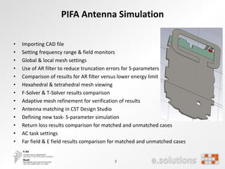
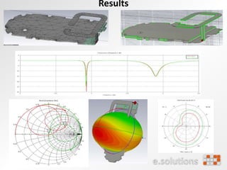
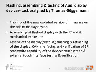
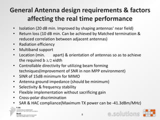
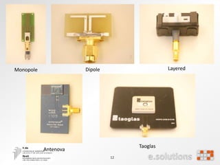
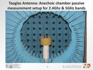
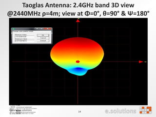
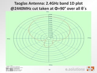
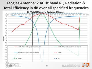
The document discusses simulation and testing of antennas for 4G LTE-MIMO systems. It describes simulating a PIFA antenna in CST Studio Suite to compare matched and unmatched cases. Results showed improved return loss and far-field patterns when the antenna was matched. Testing of a MIMO antenna system involved measuring isolation between antennas and comparing performance with the enclosure open versus closed.
![20
Ref -9 dBm Att 20 dB
RBW 500 kHz
VBW 20 Hz
SWT 2.5 s
*
*
1 PK
VIEW
2 PK
VIEW
*
A
3DB
-100
-90
-80
-70
-60
-50
-40
-30
-20
-10
1
Marker 1 [T1 ]
-20.54 dBm
5.499983974 GHz
2
Delta 2 [T2 ]
-29.06 dB
0.000000000 Hz1
Delta 1 [T1 ]
0.00 dB
0.000000000 Hz
Date: 15.JUN.2015 13:46:23
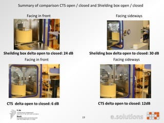
Sheilding box delta open to closed: 24dB
Ref -9 dBm Att 20 dB
*
*
1 PK
VIEW
2 PK
MAXH
*
A
3DB
RBW 500 kHz
VBW 20 Hz
SWT 2.5 s
-100
-90
-80
-70
-60
-50
-40
-30
-20
-10
1
Marker 1 [T1 ]
-20.54 dBm
5.499983974 GHz
2
Delta 2 [T2 ]
-46.83 dB
0.000000000 Hz1
Delta 1 [T1 ]
0.00 dB
0.000000000 Hz
Date: 15.JUN.2015 14:24:25
Sheilding box delta open to closed: 24dB](https://image.slidesharecdn.com/e45387f5-1619-43be-a184-ec254d457bc2-160119224512/85/VIJAY_Internship_ppt-20-320.jpg)


![Mimo [new]](https://cdn.slidesharecdn.com/ss_thumbnails/mimonew-150914045107-lva1-app6892-thumbnail.jpg?width=640&height=640&fit=bounds)


![Micro strip antenna[1]](https://cdn.slidesharecdn.com/ss_thumbnails/microstripantenna1-160907101535-thumbnail.jpg?width=640&height=640&fit=bounds)


![[Year 2012-13] Mimo technology](https://cdn.slidesharecdn.com/ss_thumbnails/mimotechnology-180701101303-thumbnail.jpg?width=640&height=640&fit=bounds)


