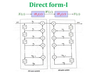
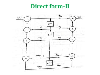
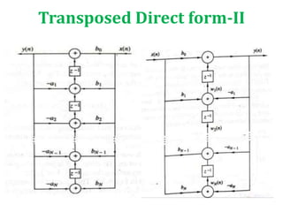
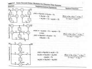
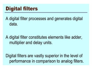
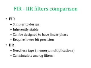
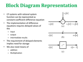
This document compares and contrasts FIR and IIR filters. It then discusses different implementation structures for digital filters, including block diagrams, FIR filter reviews, and basic IIR filter structures like direct form I and II and transposed direct form II. Basic IIR filters are characterized by rational transfer functions that can be represented using difference equations, requiring feedback and storage of delayed input, output, and intermediate values.
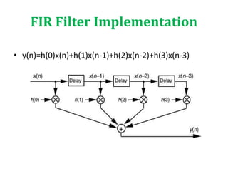
![FIR Filter Review
Z-1
Z-1
Z-1
+
h0
h1
h2
h3
x[n]
x[n-1]
y[n]
x[n-2]
x[n-3]
3
0
)(
n
n
n zhzH](https://image.slidesharecdn.com/digitalfilterstructures-191224015148/85/Digital-filter-structures-7-320.jpg)