Downloaded 101 times
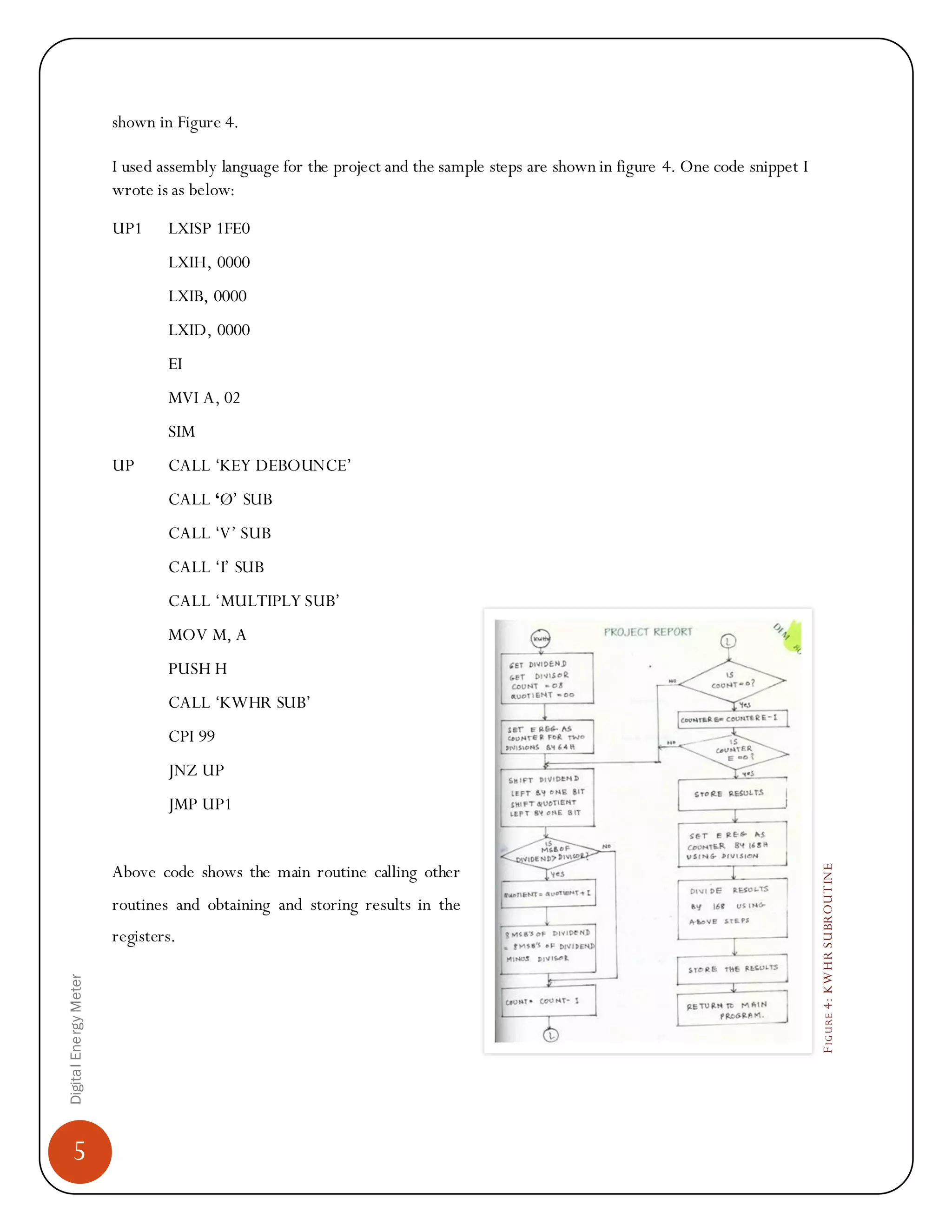

The document summarizes an engineering student's digital energy meter project. It describes the aims of replacing electromechanical meters with a more accurate digital design. Key aspects included designing hardware with components like a microprocessor, voltage and current processing modules, and developing software using assembly language. The student led a team through conceptualizing, designing, implementing, and demonstrating the working project to examiners over 7 months to complete their degree.