Download to read offline

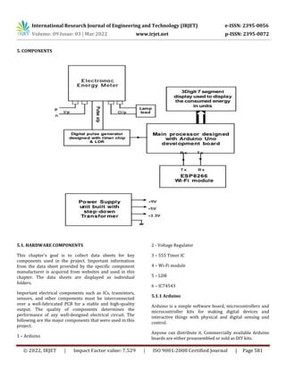
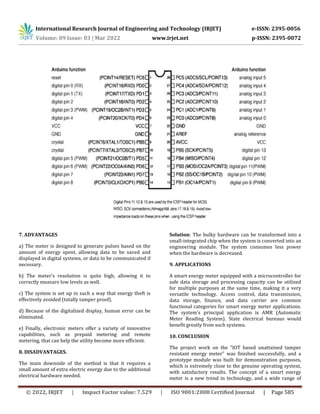

This document summarizes an IOT-based tamper-proof digital energy meter project. The key points are: 1) An electronic energy meter generates pulses based on energy consumption which are converted to digital data and sent to a smartphone via an Arduino board and WiFi module. 2) The energy meter is mounted on an electric pole out of reach of users to prevent tampering. Users can check their energy usage via a smartphone app instead of a physical meter. 3) The system aims to prevent energy theft by making the meter readings unalterable and accessible remotely through an IOT network instead of installing a meter at user premises.