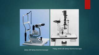
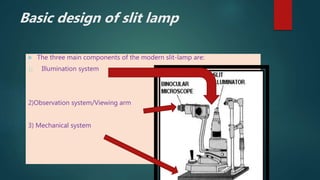
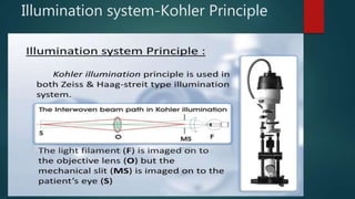
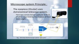
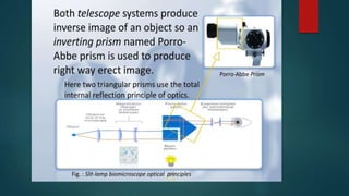
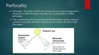
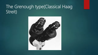
THE
BIOMICROSCOPE
(SLIT LAMP)
-DR AKSHAY NAYAK
 THE SLIT-LAMP BIOMICROSCOPE is a high-power binocular
microscope with a slit-shaped illumination source, specially
designed for viewing the different optically transparent or
translucent tissues of the eye.
 The science of examination with a slit lamp is called
Biomicroscopy as it allows in vivo study of living tissues at
high magnification.
 Allvar Gullstrand: An ophthalmologist and 1911
Nobel laureate introduced the illumination
system which had for the first time a slit
diaphragm, therefore Gullstrand is credited with
the invention of the slit lamp.
One of the most important advantages of
slit-lamp examination is that one can
examine the eye structure in three
dimensions (3D).
Binocular vision- stereopsis is provided
by slit lamp
TYPES
 There are 2 types of slit lamp biomicroscope
1)Zeiss slit lamp biomicroscope
2)Haag streit slit lamp biomicroscope
 In Zeiss type light source is at the base of the
instrument while in Haag streit type it is at
the top of the instrument.
Zeiss slit lamp biomicroscope
Haag streit slit lamp biomicroscope
 The three main components of the modern slit-lamp are:
1) Illumination system
2)Observation system/Viewing arm
3) Mechanical system
Basic design of slit lamp
Illumination system-Kohler Principle
Telescope system
 The telescope system provide considerable distance between the
microscope and the patient’s eye, so that certain maneuver like foreign
body removal from the cornea or using extra lenses for fundus
examination can be done.
Parfocality
 Parfocality : The point at which the microscope is focused corresponds to
the point on which the light is focused, this coupling effect is called
parfocality.
 This is achieved by the microscope and the illumination system, having a
common focal plane and their common axis of rotation also lies in that
focal plane.
 Illumination system
 The illumination arm and viewing arm are
parfocal.
 Light source is atop the illumination arm in a
lamp housing.
 The beam of light can be changed in
intensity,height,width,direction or angle and
color during the examination with the flick of
lever.
Observation
system(microscope)
 Observation system is essentially a compound
microscope composed of two optical elements
 1.an objective ,2.an eyepiece
 It presents to the observer an enlarged image of a near
object.
 The objective lens consists of two planoconvex lenses
with their convexities put together providing a
composite power of +22D.
 The eye piece has a lens of +10D.
 Microscope is binocular i.e. it has two eyepieces giving
binocular observer a stereoscopic view of eye.
The Grenough type(Classical Haag
Streit)
Knob to change
magnification (3
or 5step)
The Galilean Magnification changer
Mechanical system
 Joystick arrangement
 Movement of microscope and illumination system
towards and away from the eye and from side and
side is achieved via joystick arrangement.
Patient support arrangement
Vertically movable chin rest and the provision to
adjust height of table.
Fixation target:
 A movable fixation target greatly faciliates the
examination under some conditions.
Mechanical coupling :
Provides a coupling of microscope and the
illumination system along a common axis of
rotation that coincides their focal planes.
 This ensures that light falls on the point where
the microscope is focused
 Has advantages when using the slit lamp for
routine examination of anterior segment of eye.
Prerequisites :
 Switch on power & unlock base screw
 Cleaning the forehead band
 Changing paper strip from chinrest
 Comfortable sitting of pt. and the examiner
 Counseling the patient
 Proper positioning of the pt.
 Target fixation
 Adjust eyepieces to correct for examiner’s refractive error and interpupillary
distance
 Children may need to stand, or they can sit on parent’s lap or kneel on a
stable chair
Patient
positioning
Alignment
mark
Magnification
may be changed
by
flipping a lever
Changing filters. biomicroscope
Microscope and
light source
rotate
indepedently
Filters used in slit lamp biomicroscopy
 Cobalt blue filter
Used in conjunction with fluorescein stain
Dye pods in area where the corneal
epithelium is broken or absent.
 The dye absorbs blue light and emits green.
 Uses:
Ocular staining
RGP lenses fitting
Tear layer
Applanation tonometry
 Red free(green)filter:
Obscure any thing that is red hence the red
free light , thus blood vessels or
haemorrhages appears black.
This increases contrast ,revealing the path
and pattern of inflammed blood vessels.
For Rose Bengal staining evaluation.
Illumination techniques
 Includes
 Diffuse illumination
 Direct illumination
 Parallelepiped
 Optic section
 Conical(pinpoint)
 Tangential
 Specular reflection
 Indirect illumination
 Retro-illumination
 Sclerotic scatter
 Transillumination
 Proximal illumination
Diffuse illumination
 Angle between microscope and
illumination system should be 30-45
degree.
 Slit width should be widest.
 Filter to be used is diffusing filter.
 Magnification: low to medium
 Applications:
General view of anterior of eye:
lids,lashes,sclera,cornea ,iris, pupil,
Gross pathology and media opacities
Contact lens fitting.
Assessment of lachrymal reflex.
Optics of diffuse illumination Diffuse illumination with slit beam
and background illumination
 Direct Focal-
Parallelepiped:
 Constructed by narrowing the
to 1-2mm in width to illuminate a
rectangular area of cornea.
 Microscope is placed directly in
front of patients cornea.
 Light source is approximately 45
degree from straight ahead
position.
 With narrow slit the depth and portion of different
objects(penetration depth of foreign bodies, shape of
lens etc) can be resolved more easily.
 With wider slit their extension and shape are visible
more clearly.
Applications:
Used to detect and examine corneal structures and
defects.
Used to detect corneal striae that develop when
corneal edema occurs with hydrogel lens wear and
in keratoconus.
 Used to localize:
Nerve fibers
Blood vessels
Infiltrates
Cataracts
AC depth.
Corneal
epithelium-
thin,optically
empty(black)
Rest of cornea ,
lens and vitreous
are relucent-silvery
appearance.
Optical section of lens
1.Corneal scar with wide beam illumination 2.optical section through scar
indicating scar is with in superficial layer of cornea.
Conical beam(pinpoint)
Produced by narrowing the vertical height of
a parallelepiped to produce a small circular
or square spot of light.
Light source is 45-60 degree temporally and
directed into pupil.
Biomicroscope: directly in front of eye.
Magnification: high(16-25x)
Intensity of light source to heighest setting.
 Focusing:
 Beam is focused between cornea and anterior lens
surface and dark zone between cornea and anterior
lens observed.
This occurance is called tyndall phenomenon.
Tyndall phenomenon
 Cells, pigment or proteins in the
aqueous humour reflect the light like a
faint fog.
 The strongest reflection is possible at
90°.
 Most useful when examining the transparency of
anterior chamber for evidence of floating cells
and flare seen in anterior uveitis.
Specular reflection
 Established by separating the microscope and
slit beam by equal angles from normal to
cornea.
 Based on snell’s law
 Angle of illuminator to microscope must be
equal and opposite.
 Angle of light should be moved until a very
bright reflex obtained from corneal surface
which is called zone of specular reflection.
SPEC(tacular) lake REFLECTION
 When such an area of reflection is established on corneal
endothelium, its possible to see individual endothelial cells. Its
because minute irregularities in the tissues cause some light in the
zone of reflection not to be reflected to examiner.
 Irregularities ,deposits ,or excavasation in these smooth surface will
fail to reflect light and these appears darker than surrounding IN
OTHERWISE BRIGHT ZONE.
 Under specular reflection anterior corneal surface appears as white
uniform surface and corneal endothelium takes on a mosaic pattern.
 Used to observe:
 Evaluate general appearance of corneal endothelium
 Lens surfaces
 Corneal epithelium
Schematic of specular reflection.
Reflection from
front surface endothelium
Indirect illumination
 The beam is focused in an area adjacent to ocular tissue to be
observed.
 Main application:
 Examination of objects in direct vicinity of corneal areas of
reduced transparency e,g, infiltrates,corneal
scars,deposits,epithelial and stromal defects
 Illumination:
 Narrow to medium slit beam
 Decentred beam
Retroillumination
 Formed by reflecting light of slit beam
from a structure more posterior than the
structure under observation.
 A vertical slit beam 1-4mm wide can be
used.
 Purpose:
Place object of regard against a bright
background allowing object to appear
dark or black.
Used most often in searching for keratic
precipitates and other debris on corneal
endothelium.
The crystalline lens can also be
retroilluminated for viewing of water clefts and
vacuoles of anterior lens and posterior
subcapsular cataract.
 Direct retroillumination from iris:
Used to view corneal pathology.
A moderately wide slit beam is aimed
towards the iris directly behind the
corneal anomaly.
Schematic of
direct retroillumination from
the iris.
direct retroillumination from the iri
 Indirect retroillumination from iris:
 Performed as with direct retroillumination but
the beam is directed to an area of the iris
bordering the portion of iris behind pathology.
 It provides dark background allowing corneal
opacities to be viewed with more contrast.
 Observe:
Cornea, angles.
Direct type: Cornea illuminated by
light is viewed directly.
Indirect type: Cornea viewed
adjacent to area of illuminated by
the reflected light.
Retroillumination from fundus(red reflex
photography)
 The slit illuminator is positioned in an almost
coaxial position with the biomicroscope.
 A wide slit beam is decentered and adjusted
to a half circle by using the slit width.
 The decentred slit beam is projected near
the pupil margin through a dilated pupil.
Schematic of
retroillumination from the
retina.
Example of retroillumination from the retina.
Uses of retro illumination
To see
 Lattice dystrophy
 Pseudoexfoliation
 Keratic precipitates
 Corneal scars
 Lens vacuoles
 Cataract
Sclerotic scatter
 It is formed by focusing a bright but narrow slit beam on the
limbus and using microscope on low magnification.
 Such an illumination technique causes cornea to take on
total internal reflection.
 The slit beam should be placed approximately 40-60 degree
from the microscope.
 Corneal changes or abnormalities can be visualized by
reflecting the scattered light- especially subtle opacities.
Schematic of
sclerotic scatter. Example of
sclerotic scatter.
OSCILLATORY
ILLUMINATION
Transillumination
 In transillumination, a structure (in the eye, the iris) is
evaluated by how light passes through it.
 Iris transillumination:
 This technique also takes advantage of the red
reflex.
 The pupil must be at mid mydriasis (3to 4 mm
when light stimulated).
 Place the light source coaxial (directly in line) with
the microscope.
.
 Normally the iris pigment absorbs the
light, but pigmentation defects let the
red fundus light pass through..
 Observe: iris defects (they will glow with
the orange light reflected from the
fundus)
Order of examination on slit lamp
Uses of slit lamp biomicroscopy
 Diagnostic:
 Anterior segment and posterior segment diseases
 Dry eye
 Procedures:
 Applanation
 Tear evaluation
 Pachymetry
 Gonioscopy
 Contact lens fitting
 Therapeutic:
 Laser
 FB removal
 Epilation
 Yag capsulotomy
Anterior and posterior segment disease evaluation
 Lids and lashes
 Conjunctiva and cornea
 Instillation of fluorescein and BUT
measurement
 Eversion of the lids
 Anterior chamber and angle measurement
 Iris
 Crystalline lens
 Anterior vitreous
Injected conjunctivaMeibomian gland openings
pinquecula,
INSTILLATION OF FLUORESCEIN PALPEBRAL CONJUNCTIVA
EXAMINATION
Van Herrick Technique
 Used to evaluate angle of anterior chamber without gonioscopy
 Narrow slit angled at 60degrees at limbus
 Medium Magnification
 Depth of anterior chamber is evaluated to the thickness of cornea.
Gonioscopy via slit lamp
 Single mirror gonioscope
 Angle of anterior chamber
 Three mirror gonioscope
 Fundus(central and peripheral) and angle of anterior
chamber
CENTRAL RETINA PHOTOGRAPHS WITH A 90-
DIOPTER LENS
 A moderate slit
beam in the
almost coaxial
position gives
the best results.
 THANK YOU
 ….

The Slit lamp Biomicroscope

  • 1.
  • 2.
     THE SLIT-LAMPBIOMICROSCOPE is a high-power binocular microscope with a slit-shaped illumination source, specially designed for viewing the different optically transparent or translucent tissues of the eye.  The science of examination with a slit lamp is called Biomicroscopy as it allows in vivo study of living tissues at high magnification.
  • 3.
     Allvar Gullstrand:An ophthalmologist and 1911 Nobel laureate introduced the illumination system which had for the first time a slit diaphragm, therefore Gullstrand is credited with the invention of the slit lamp.
  • 4.
    One of themost important advantages of slit-lamp examination is that one can examine the eye structure in three dimensions (3D). Binocular vision- stereopsis is provided by slit lamp
  • 5.
    TYPES  There are2 types of slit lamp biomicroscope 1)Zeiss slit lamp biomicroscope 2)Haag streit slit lamp biomicroscope  In Zeiss type light source is at the base of the instrument while in Haag streit type it is at the top of the instrument.
  • 6.
    Zeiss slit lampbiomicroscope Haag streit slit lamp biomicroscope
  • 7.
     The threemain components of the modern slit-lamp are: 1) Illumination system 2)Observation system/Viewing arm 3) Mechanical system Basic design of slit lamp
  • 8.
  • 12.
    Telescope system  Thetelescope system provide considerable distance between the microscope and the patient’s eye, so that certain maneuver like foreign body removal from the cornea or using extra lenses for fundus examination can be done.
  • 13.
    Parfocality  Parfocality :The point at which the microscope is focused corresponds to the point on which the light is focused, this coupling effect is called parfocality.  This is achieved by the microscope and the illumination system, having a common focal plane and their common axis of rotation also lies in that focal plane.
  • 14.
     Illumination system The illumination arm and viewing arm are parfocal.  Light source is atop the illumination arm in a lamp housing.  The beam of light can be changed in intensity,height,width,direction or angle and color during the examination with the flick of lever.
  • 15.
    Observation system(microscope)  Observation systemis essentially a compound microscope composed of two optical elements  1.an objective ,2.an eyepiece  It presents to the observer an enlarged image of a near object.  The objective lens consists of two planoconvex lenses with their convexities put together providing a composite power of +22D.  The eye piece has a lens of +10D.  Microscope is binocular i.e. it has two eyepieces giving binocular observer a stereoscopic view of eye.
  • 17.
  • 18.
    Knob to change magnification(3 or 5step) The Galilean Magnification changer
  • 19.
    Mechanical system  Joystickarrangement  Movement of microscope and illumination system towards and away from the eye and from side and side is achieved via joystick arrangement. Patient support arrangement Vertically movable chin rest and the provision to adjust height of table.
  • 20.
    Fixation target:  Amovable fixation target greatly faciliates the examination under some conditions. Mechanical coupling : Provides a coupling of microscope and the illumination system along a common axis of rotation that coincides their focal planes.  This ensures that light falls on the point where the microscope is focused  Has advantages when using the slit lamp for routine examination of anterior segment of eye.
  • 22.
    Prerequisites :  Switchon power & unlock base screw  Cleaning the forehead band  Changing paper strip from chinrest  Comfortable sitting of pt. and the examiner  Counseling the patient  Proper positioning of the pt.  Target fixation  Adjust eyepieces to correct for examiner’s refractive error and interpupillary distance  Children may need to stand, or they can sit on parent’s lap or kneel on a stable chair Patient positioning Alignment mark
  • 23.
    Magnification may be changed by flippinga lever Changing filters. biomicroscope Microscope and light source rotate indepedently
  • 24.
    Filters used inslit lamp biomicroscopy  Cobalt blue filter Used in conjunction with fluorescein stain Dye pods in area where the corneal epithelium is broken or absent.  The dye absorbs blue light and emits green.  Uses: Ocular staining RGP lenses fitting Tear layer Applanation tonometry
  • 26.
     Red free(green)filter: Obscureany thing that is red hence the red free light , thus blood vessels or haemorrhages appears black. This increases contrast ,revealing the path and pattern of inflammed blood vessels. For Rose Bengal staining evaluation.
  • 29.
    Illumination techniques  Includes Diffuse illumination  Direct illumination  Parallelepiped  Optic section  Conical(pinpoint)  Tangential  Specular reflection  Indirect illumination  Retro-illumination  Sclerotic scatter  Transillumination  Proximal illumination
  • 30.
    Diffuse illumination  Anglebetween microscope and illumination system should be 30-45 degree.  Slit width should be widest.  Filter to be used is diffusing filter.  Magnification: low to medium
  • 31.
     Applications: General viewof anterior of eye: lids,lashes,sclera,cornea ,iris, pupil, Gross pathology and media opacities Contact lens fitting. Assessment of lachrymal reflex.
  • 32.
    Optics of diffuseillumination Diffuse illumination with slit beam and background illumination
  • 33.
     Direct Focal- Parallelepiped: Constructed by narrowing the to 1-2mm in width to illuminate a rectangular area of cornea.  Microscope is placed directly in front of patients cornea.  Light source is approximately 45 degree from straight ahead position.
  • 34.
     With narrowslit the depth and portion of different objects(penetration depth of foreign bodies, shape of lens etc) can be resolved more easily.  With wider slit their extension and shape are visible more clearly. Applications: Used to detect and examine corneal structures and defects. Used to detect corneal striae that develop when corneal edema occurs with hydrogel lens wear and in keratoconus.
  • 35.
     Used tolocalize: Nerve fibers Blood vessels Infiltrates Cataracts AC depth.
  • 36.
    Corneal epithelium- thin,optically empty(black) Rest of cornea, lens and vitreous are relucent-silvery appearance.
  • 37.
    Optical section oflens 1.Corneal scar with wide beam illumination 2.optical section through scar indicating scar is with in superficial layer of cornea.
  • 38.
    Conical beam(pinpoint) Produced bynarrowing the vertical height of a parallelepiped to produce a small circular or square spot of light. Light source is 45-60 degree temporally and directed into pupil. Biomicroscope: directly in front of eye. Magnification: high(16-25x) Intensity of light source to heighest setting.
  • 39.
     Focusing:  Beamis focused between cornea and anterior lens surface and dark zone between cornea and anterior lens observed. This occurance is called tyndall phenomenon.
  • 40.
    Tyndall phenomenon  Cells,pigment or proteins in the aqueous humour reflect the light like a faint fog.  The strongest reflection is possible at 90°.  Most useful when examining the transparency of anterior chamber for evidence of floating cells and flare seen in anterior uveitis.
  • 42.
    Specular reflection  Establishedby separating the microscope and slit beam by equal angles from normal to cornea.  Based on snell’s law  Angle of illuminator to microscope must be equal and opposite.  Angle of light should be moved until a very bright reflex obtained from corneal surface which is called zone of specular reflection.
  • 43.
  • 44.
     When suchan area of reflection is established on corneal endothelium, its possible to see individual endothelial cells. Its because minute irregularities in the tissues cause some light in the zone of reflection not to be reflected to examiner.  Irregularities ,deposits ,or excavasation in these smooth surface will fail to reflect light and these appears darker than surrounding IN OTHERWISE BRIGHT ZONE.  Under specular reflection anterior corneal surface appears as white uniform surface and corneal endothelium takes on a mosaic pattern.  Used to observe:  Evaluate general appearance of corneal endothelium  Lens surfaces  Corneal epithelium
  • 45.
    Schematic of specularreflection. Reflection from front surface endothelium
  • 46.
    Indirect illumination  Thebeam is focused in an area adjacent to ocular tissue to be observed.  Main application:  Examination of objects in direct vicinity of corneal areas of reduced transparency e,g, infiltrates,corneal scars,deposits,epithelial and stromal defects  Illumination:  Narrow to medium slit beam  Decentred beam
  • 47.
    Retroillumination  Formed byreflecting light of slit beam from a structure more posterior than the structure under observation.  A vertical slit beam 1-4mm wide can be used.  Purpose: Place object of regard against a bright background allowing object to appear dark or black.
  • 48.
    Used most oftenin searching for keratic precipitates and other debris on corneal endothelium. The crystalline lens can also be retroilluminated for viewing of water clefts and vacuoles of anterior lens and posterior subcapsular cataract.
  • 49.
     Direct retroilluminationfrom iris: Used to view corneal pathology. A moderately wide slit beam is aimed towards the iris directly behind the corneal anomaly.
  • 50.
    Schematic of direct retroilluminationfrom the iris. direct retroillumination from the iri
  • 51.
     Indirect retroilluminationfrom iris:  Performed as with direct retroillumination but the beam is directed to an area of the iris bordering the portion of iris behind pathology.  It provides dark background allowing corneal opacities to be viewed with more contrast.  Observe: Cornea, angles.
  • 52.
    Direct type: Corneailluminated by light is viewed directly. Indirect type: Cornea viewed adjacent to area of illuminated by the reflected light.
  • 53.
    Retroillumination from fundus(redreflex photography)  The slit illuminator is positioned in an almost coaxial position with the biomicroscope.  A wide slit beam is decentered and adjusted to a half circle by using the slit width.  The decentred slit beam is projected near the pupil margin through a dilated pupil.
  • 54.
    Schematic of retroillumination fromthe retina. Example of retroillumination from the retina.
  • 55.
    Uses of retroillumination To see  Lattice dystrophy  Pseudoexfoliation  Keratic precipitates  Corneal scars  Lens vacuoles  Cataract
  • 56.
    Sclerotic scatter  Itis formed by focusing a bright but narrow slit beam on the limbus and using microscope on low magnification.  Such an illumination technique causes cornea to take on total internal reflection.  The slit beam should be placed approximately 40-60 degree from the microscope.  Corneal changes or abnormalities can be visualized by reflecting the scattered light- especially subtle opacities.
  • 58.
    Schematic of sclerotic scatter.Example of sclerotic scatter.
  • 59.
  • 60.
    Transillumination  In transillumination,a structure (in the eye, the iris) is evaluated by how light passes through it.  Iris transillumination:  This technique also takes advantage of the red reflex.  The pupil must be at mid mydriasis (3to 4 mm when light stimulated).  Place the light source coaxial (directly in line) with the microscope. .
  • 61.
     Normally theiris pigment absorbs the light, but pigmentation defects let the red fundus light pass through..  Observe: iris defects (they will glow with the orange light reflected from the fundus)
  • 62.
  • 63.
    Uses of slitlamp biomicroscopy  Diagnostic:  Anterior segment and posterior segment diseases  Dry eye  Procedures:  Applanation  Tear evaluation  Pachymetry  Gonioscopy  Contact lens fitting  Therapeutic:  Laser  FB removal  Epilation  Yag capsulotomy
  • 64.
    Anterior and posteriorsegment disease evaluation  Lids and lashes  Conjunctiva and cornea  Instillation of fluorescein and BUT measurement  Eversion of the lids  Anterior chamber and angle measurement  Iris  Crystalline lens  Anterior vitreous
  • 65.
    Injected conjunctivaMeibomian glandopenings pinquecula, INSTILLATION OF FLUORESCEIN PALPEBRAL CONJUNCTIVA EXAMINATION
  • 67.
    Van Herrick Technique Used to evaluate angle of anterior chamber without gonioscopy  Narrow slit angled at 60degrees at limbus  Medium Magnification  Depth of anterior chamber is evaluated to the thickness of cornea.
  • 68.
    Gonioscopy via slitlamp  Single mirror gonioscope  Angle of anterior chamber  Three mirror gonioscope  Fundus(central and peripheral) and angle of anterior chamber
  • 72.
    CENTRAL RETINA PHOTOGRAPHSWITH A 90- DIOPTER LENS  A moderate slit beam in the almost coaxial position gives the best results.
  • 75.