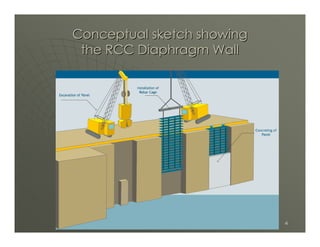
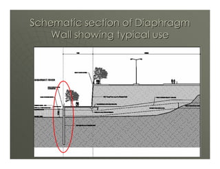
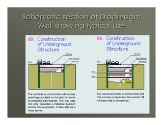
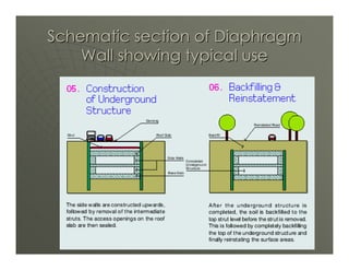
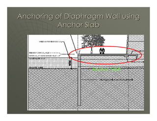
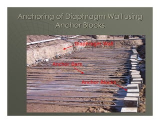
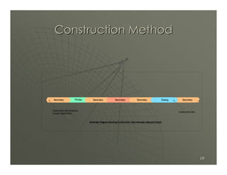
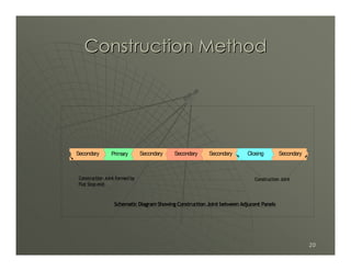
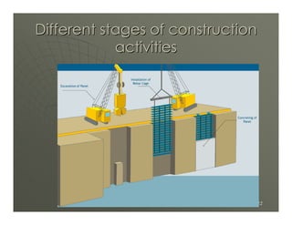
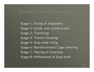
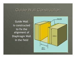
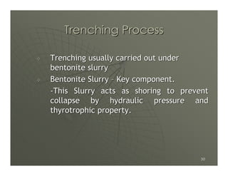
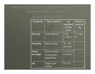
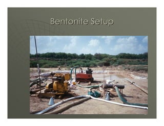
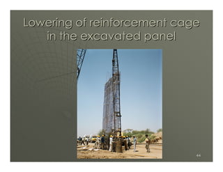
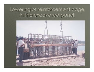
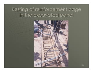
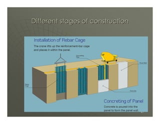
The document discusses the construction of diaphragm walls. Diaphragm walls are reinforced concrete walls constructed underground using an excavation technique that keeps the trench full of a bentonite slurry. They are commonly used for deep basements and where construction time is limited. The construction process involves excavating trenches in panels, installing stop ends between panels, placing reinforcement cages, and pouring concrete through a tremie pipe to displace the slurry. Proper installation and maintenance of the bentonite slurry is crucial to prevent trench collapse during excavation and concrete placement.
Diaphragm walls are underground structural elements.
It is an in-situ reinforced concrete structure that is constructed panel by panel.
Diaphragm walls are ideal for soft clays and loose sands below the water table where there is a need to control lateral movements.
Diaphragm wall: Construction and DesignUmer Farooq
Diaphragm walls are concrete or reinforced concrete walls constructed in slurry-supported, open trenches below existing ground.
Concrete is placed using the Tremie installation method or by installing pre-cast concrete panels (known as a pre-cast diaphragm wall). Diaphragm walls can be constructed to depths of 150 meters and to widths of 0.5 to 1.50 meters.
house foundation types
foundation types for building
raised foundation types
small building foundation types
types of building foundations pdf
commercial building foundation types
home building foundation types
how to build a house foundation
types of foundations in construction
types of house foundations
how to build a foundation
The vacuum dewatering process basically improves strength, durability, and other properties of concrete by reducing the water-cement ratio immediately after the mix is placed, usually in floors and other flatwork. A Bridgeport, Connecticut vacuum dewatering demonstration, although it involved no new ...
vacuum dewatering system
vacuum dewatering pump
vacuum dewatering box
wellpoint pump systems
dewatering pump system
dewatering pump
dewatering wellpoint
small wellpoint dewatering systems
interesting civil engineering topics
civil engineering topics for presentation
civil seminar topics ppt
civil engineering seminar topics 2018
best seminar topics for civil engineering
seminar topics pdf
seminar topics for mechanical engineers
seminar topic for civil engineering pdf
Micro-piling is one of the efficient and cost effective ground improvement technique which can be use various condition. It can use to support foundation as well as soil retention.
Practices in Planning, Design and Construction of Head Race Tunnel of a Hydro...Mohit Shukla
This paper has been selected for oral presentation as well as inclusion in the conference proceedings of the ICCCGE 2016 : 18th International Conference on Civil,Construction and Geological Engineering held in Toronto, Canada during June,
13-14, 2016. This paper was also able to find a position in the international conference of Dams and Hydropower held at Laos in May 2016.
A presentation of a precast segmental casting yard setup showing the required sequential steps. At the time, I worked for Parsons Brinckerhoff as Lead Construction Engineer.
tunnel lining may be permanent or temporary based upon their use and requirement. design of lining is done in two parts one is temporary or initial lining design and other is permanent design of the lining. empirical and theoretical methods are major design methods.
Join Ron Prychitko & Lorne Mielty for an overview of various Bridge-Plate, Multi-Plate and Tunnel Liner Plate applications. Through the presentation of various case studies they will cover product selection criteria for corrugated steel plate structures and best practices including assembly and installation.
Case study examples will include bridges, culverts, wildlife passes, mine portals, pedestrian tunnels and more.
What You’ll Learn:
-Learn about unique applications that solve demanding -problems
-Advantages of soil/steel structures
-Construction process for structures
-Available product, application and design resources
-General Canadian Codes and Standards will be referenced
Who Should Attend
-Bridge / Structural Engineers
-Municipal & Transportation Engineers
-Municipal, Provincial and Federal Infrastructure personnel
-Developers
-Earthworks & Highways Contractors
-Mining Engineers & Contractors
-Road Superintendents
Areas related to circles - Area of sector and segment of a circle (Class 10 m...Let's Tute
Areas related to circles - Area of sector and segment of a circle (Class 10 maths).
Let's tute is an E-school or E- platform which is free for the student.Students will watch "MATHS" Videos for conceptual understanding.
Contact Us -
Website -www.letstute.com
YouTube - www.youtube.com/letstute
special concrete and high performance concreteErankajKumar
GROUTING OF CONCRETE, advantage ofGrouting,Characteristics of Grouting, GUNTING OF
CONCRETE, Application of Guniting, Properties of Guniting, advantage and disadvantage of Guniting, UNDERWATER CONCRETING, Properties of underwater concrete, METHODS OF UNDERWATER CONCRETE, advantage and disadvantage of underwater concrete, HOT WEATHERING CONCRETE, precautions, COLD WEATHER CONCRETING, PUMPABLE CONCRETE, Requirements of Mix Design for Pumpable Concrete, Ready Mixed Concrete RMC, Types of Ready Mixed Concrete, advantage and disadvantage of ready mixed concrete, introduction in High performance concrete HPC, selection of materials, behaviour of fresh high performance concrete HPC , behaviour of Hardened High performance concrete HPC when to use High performance concrete HPC , application of HPC , Advantage of HPC , Limitations of HPC
Useful for Second year Civil Engineering Students of Savitribai Phule Pune university, Pune (University of Pune)
This PPT shows Properties, testing and analysis of Fresh concrete, from the subject Concrete Technology.
Few more PPTs and Videos are available at my blog tusharhsonawane.wordpress.com
3. Introduction
Diaphragm Wall is generally reinforced
concrete wall constructed in the ground using
Underslurry technique which was developed in
Europe.
The technique involves excavating a narrow
trench that is kept full of an engineered fluid
of slurry.
Walls of thickness between 300 and 1200 mm
can be formed in this way up to a depths of 45
meters.
3
5. Diaphragm wall-Application
Commonly used in congested areas
-Can be Installed in close proximity to
existing structure
Practically suited for deep basements
Used in conjunction with “Top Down”
construction technique
5
11. Anchoring of Diaphragm Wall using
Anchor Blocks
Diaphragm Wall
Anchor Bars
Anchor Blocks
11
12. Important Conditions
Dictate the use of Diaphragm Wall
Very unstable soil profiles below the water
table
Limited construction time
Where deeper than normal cantilever support
may be required
12
13. Positive facades of Diaphragm
Wall
Can be Installed to considerable depth
Formation of walls with substantial thickness
Flexible system in plan layout
Easily incorporated into Permanent works
Designable to carry vertical loads
Construction time of Basement can be lowered
considerably.
Economic and Positive solution for large deep
basement in saturated and unstable soil profiles.
Can be used for seepage control in Dams.
Noise levels limited to engine noise only.
No vibration during installation.
13
14. Negative Facades of
Diaphragm Wall
Not economical for small, shallow Basements
14
15. Category of Diaphragm wall
1) In Situ Cement Bentonite Vertical Wall
2) In Situ RCC Vertical Wall
3) Precast RCC Vertical Wall
15
16. In Situ Cement Bentonite
Vertical Wall
Provides water tight barrier
Used to prevent seepage/water loss from
Natural reservoir and Dams
16
17. In Situ RCC Vertical Wall
Underground Structural element
Used for Retention systems and Permanent
foundation walls
Deep groundwater barriers
17
18. Procedure
Diaphragm Wall construction begins with
the trench being excavated in
discontinuous sections or “panels”.
Stop-ends are placed vertically at each end
of primary panel to form joints for
adjacent secondary panel or closing
panels. Panels are usually 4 to 6 meters
long. Stop-ends are used to form the joints
between adjacent panels and a water bar
can be incorporated across these joints.
18
19. Construction Method
Secondary Primary Secondary Secondary Secondary Closing Secondary
Construction Joint formed by
Construction Joint
Circular Stopend Pipe
Schematic Diagram Showing Construction Joint between Adjucent Panels
19
20. Construction Method
Secondary Primary Secondary Secondary Secondary Closing Secondary
Construction Joint formed by Construction Joint
Flat Stop end
Schematic Diagram Showing Construction Joint between Adjucent Panels
20
30. Trenching Process
Trenching usually carried out under
bentonite slurry
Bentonite Slurry – Key component.
-This Slurry acts as shoring to prevent
collapse by hydraulic pressure and
thyrotrophic property.
30
31. Bentonite Slurry
Used as a support fluid
The bentonite suspension used in bore holes
is basically a clay of montmorillonite group
having exchangeable sodium cations (Na+).
The action of bentonite in stabilizing the
sides of bore holes is primarily due to the
thixotropic property of bentonite
suspension.
The bentonite suspension when undisturbed
forms a jelly which when agitated becomes a
fluid again.
31
32. Functions of Bentonite
In case of granular soils, the bentonite
suspension penetrates into the sides under
positive pressure and after a while forms a
jelly.
The bentonite suspension gets deposited on
the sides of the hole resulting in the
formation of a filter cake in contact with
soil against which the fluid pressure acts.
In case of impervious clay, the bentonite
does not penetrate into the soil, but
deposits only a thin film on the surface of
the hole.
32
33. Factors affecting stability
of Trench
Level of the supporting fluid
-Level of the bentonite slurry should be
maintained preferably at least 1.5m above the
ground water level to avoid problem of
instability.
Density and Viscosity of supporting fluid
Loss of shear strength with time
Suction effect during trenching
33
34. Specification of Bentonite
(as per IS:2911-Part1:Sec2)
Liquid limit : 300 to 450 % (in accordance
with IS:2720-part V )
Sand content : Less than 7 %
Density: 1.12
Marsh viscosity : About 37 second, tested by
Marsh cone
Swelling index: Swelling index at least 2 times
of dry volume.
pH value : Less than 11.5
34
35. Tests and compliance values for support fluid
prepared from bentonite
(as per IS9556-1980)
Property Test method As Before
supplied concret
to the ing
bore
Density Mud balance 1.04- <1.15g/
1.10g/m ml
l
Viscosity Marsh cone 30 - 90
seconds
Shear Shearometer / 1.4 to 10
strength Vane shear N/sq.m
apparatus
pH Digital pH 9.5-12
meter 35
36. Schematic Diagram of
Bentonite Setup
•Storage tanks
Settling Circulation Fresh
T3 T2 T1
Mixer
•Mud
Pump
Diaphragm Wall Construction area
36
38. Preparation of Bentonite Slurry
Bentonite slurry made by passing dry powder
through water jet. A conical hopper is used
with bottom nozzle through which water is
pumped under pressure. The bentonite powder
is poured directly from top and when it falls
down the hopper, it gets agitated in the water.
After getting circulated, the mixed bentonite
thus falls in the tank.
38
39. Trench Cleaning
Joints of adjacent panels to be cleaned to
obtain watertight bond
Loose materials to be lifted by suitable air
lifting method
39
40. Fixing of Stop ends
Stop ends to be fixed at the proper
position keeping it truly vertical
Distance between two Stop ends to be
fixed as per prefixed Panel Layout
40
48. Placing of Concrete
Placing of concrete having slump 150mm to
190mm by tremmie method
Concrete to be placed through a top metal hopper
and into a rigid leak proof tremmie pipe (2 sets),
sufficiently large enough to permit free flow of
concrete.
Initially there should be a suitable plug at the
bottom of metal hopper, which will not discharge
concrete until sufficient concrete accumulate in
the metal hopper.
concrete displaces the slurry from bottom and
rises in such a manner that mixing of concrete
with slurry does not occurs
48
50. Placing of Concrete
Pouring shall be continued till it
accumulates in vertical Tremmie pipe up
to top of funnel.
Tremmie pipe shall be raised so as to
release the concrete in a single continuous
flow.
Concrete to be discharged in the trench
without any lateral movement of Tremmie
pipe.
50
51. Placing of Concrete
Caution - Bottom end of Tremmie pipe
must remains immersed in concrete.
Operation to be continued till good
concrete reaches 300mm above the
cut-off level of Diaphragm Wall.
This concrete above cut-off shall be
removed when green Chipping of concrete
is not to be permitted.
Length of Tremmie pipe shall be reduced
by removal of Tremmie segment stage by
stage. 51
52. Withdrawal of Stop ends
Withdrawal of Stop ends just after the
Initial setting of concrete.
If retarders are not added, Stop End Pipes
shall be moved up & down not later than
45 minutes from the time of placing of
concrete.
52
53. Thank You
If any Query please mail me-
gagangoswami@yahoo.co.in
53