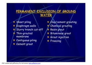
SlideShare a Scribd company logo
1 of 34
Download to read offline
Substructure


                                               Ground Water Control
                                                 Soil Stabilization

PDF created with pdfFactory Pro trial version www.pdffactory.com
Ground Water Control
                   Ground water can be defined as water which is held
                   temporarily in the soil above the level of the water
                   table.
                   Below the water table level is the subsoil water which
                   is the result of the natural absorption by subsoils of
                   the ground water.
                   Both types of water can be effectively controlled by a
                   variety of methods which have been designed either to
                   exclude the water from a particular area or merely to
                   lower the water table to give reasonably dry working
                   conditions especially for excavation activities.
                   The voids caused by excavation works encourage water
                   to flow since the opposition to the ground water
                   movement provided by the soil has been removed.


PDF created with pdfFactory Pro trial version www.pdffactory.com
Exclusion of ground water can be
                 classified into 2 groups:

                       Permanent exclusion of ground water.

                       Temporary exclusion of ground water
                       by lowering the water table.


PDF created with pdfFactory Pro trial version www.pdffactory.com
PERMANENT EXCLUSION OF GROUND
                                   WATER

                       Sheet piling                                Clay/cement grouting
                       Diaphragm walls                             Chemical grouting
                       Slurry trench cut-off                       Resin grout
                       Thin-grouted                                Bituminous grout
                       membrane                                    Grout injection
                       Contiguous piling                           Freezing
                       Cement grout


PDF created with pdfFactory Pro trial version www.pdffactory.com
TEMPORARY EXCLUSION OF GROUND
                                   WATER

                       Sump pumping
                       Well-point system
                       Shallow bored wells
                       Deep bored wells
                       Horizontal ground water control
                       Electro osmosis


PDF created with pdfFactory Pro trial version www.pdffactory.com
Sheet piling (Permanent Exclusion)

                       Suitable for all types of soils except boulder beds
                       and is used to form a barrier or cut off wall to the
                       flow of ground water.
                       The sheet pile can be a permanent nature, being
                       designed to act as retaining wall or it can be a
                       temporary enclosure to excavation works in the
                       form of cofferdam.


PDF created with pdfFactory Pro trial version www.pdffactory.com
Diaphragm walls

                       Suitable for all types of soils and are usually of in
                       situ r.c. installed using the bentonite slurry
                       method.
                       This form of diaphragm wall has the advantages of
                       low installation noise and vibration, can be used in
                       restricted spaces and can be installed close to
                       existing foundations.
                       Generally, unless the diaphragm wall forms part of
                       the permanent structure, this method is
                       uneconomic.


PDF created with pdfFactory Pro trial version www.pdffactory.com
Slurry trench cut off

                       These are non structural thin cast in situ
                       unreinforced diaphragm walls suitable for subsoil
                       of silts, sands and gravels.
                       They can be used on sites where there is
                       sufficient space to enclose the excavation area
                       with a cut off wall of this nature sited so that
                       there is sufficient earth remaining between the
                       wall and the excavation to give the screen or
                       diaphragm wall support.
                       Provided adequate support is given these walls are
                       rapidly installed and are cheaper than the
                       structural version.


PDF created with pdfFactory Pro trial version www.pdffactory.com
Contiguous piling

                       An alternative method to the reinforced concrete
                       diaphragm wall consisting of a series of
                       interlocking reinforced concrete bore pile.
                       Contiguous pile can be faced with a reinforced
                       rendering or covered with a mesh reinforcement
                       sprayed with concrete to give smooth finish.
                       This method is called Shotcrete/Gunite.
                       An alternative method is to cast in front of the
                       contiguous piling a reinforced wall terminating in a
                       capping beam to the pile. Fig. II.36


PDF created with pdfFactory Pro trial version www.pdffactory.com
Cement grout
                   In common with all grouting methods cement grouts are
                   used to form a ‘curtain’ in soils which have high
                   permeability making temporary exclusion pumping
                   methods uneconomics.
                   Cement grouts are used in fissured and jointed rock
                   stratas and are injected into the ground through a series
                   of grouting holes bored into the ground in lines with
                   secondary intermediate boreholes lines if necessary.
                   The grout can be a mixture of neat cement and water,
                   cement and sand up to ratio of 1:4 or PFA(pulverised fuel
                   ash) and cement in the ratio of 1:1 with 2 parts of water
                   by weight.
                   The usual practice is to start with a thin grout and
                   gradually reduce the water: cement ratio as the process
                   proceeds to increase the viscosity of the mixture.
                   To be effective, this form of treatment needs to be
                   extensive.

PDF created with pdfFactory Pro trial version www.pdffactory.com
Clay/Cement Grout
                       Suitable for sands and gravels where the soil
                       particles are too small for cement grout
                       treatment.
                       The grout is introduced by means of sleeve grout
                       pipe which limits its spread and like the cement
                       grouting, the equipment is simple and can be used
                       in a confined space.
                       The clay/cement grout is basically bentonite with
                       additives such as Portland cement or soluble
                       silicates to form the permanent barrier.
                       One disadvantage of this method is that at least
                       4.00m of natural cover is required to provide
                       support for the non structural barrier.


PDF created with pdfFactory Pro trial version www.pdffactory.com
Chemical Grouting
                  Suitable for use in medium to coarse sands and gravels to stabilise
                  the soil and can also be used for underpinning works below the
                  water table level.
                  The chemicals are usually mixed prior to their injection into the
                  ground through injection pipes inserted at 600mm centres.
                  The chemicals form a permanent gel or sol in the earth which
                  increases the strength of the soil and also reduces its
                  permeability.
                  This method in which a liquid base diluted with water is mixed with
                  a catalyst to control the gel setting time before being injected
                  into the ground is called the one shot method. (action delayed!)
                  An alternative two shot method can be used and is carried out by
                  injecting the first chemical (usually sodium silicate) into the
                  ground and immediately afterwards injecting the second chemical
                  (calcium chloride) to form a ‘silica gel’. (action immediate!)
                  One disadvantage is the nedd for at least 2.00m of natural cover.


PDF created with pdfFactory Pro trial version www.pdffactory.com
Resin Grout

                       Suitable for silty fine sands or for use in conjunction with
                       clay/cement grouts for treating fine strata but like the
                       chemical grout described.
                       They can be costly unless used on large works.
                       Resin grout are similar in application to the chemical grouts
                       but having a low viscosity and this enables them to penetrate
                       the fine sands unsuitable for chemical grouting application.


PDF created with pdfFactory Pro trial version www.pdffactory.com
Bituminous Grout

                       Suitable for injection into fine sands to decrease the
                       permeability of the soil but they will not increase the
                       strength of the soil and therefore unsuitable for
                       underpinning work.


PDF created with pdfFactory Pro trial version www.pdffactory.com
Grout Injection

                       Grouts of all kinds are usually injected into the subsoil by
                       pumping in the mixture at high pressure through tubes
                       placed at the appropriate centres according to the solution
                       being used and/or the soil type.


PDF created with pdfFactory Pro trial version www.pdffactory.com
Freezing

                       Suitable method for all types of subsoils with a moisture
                       content in excess of 8% of the voids.
                       The basic principle is to insert freezing tubes into the
                       ground and circulate a freezing solution around the tubes to
                       form ice in the voids, thus creating a wall of ice to act as the
                       impermeable barrier.
                       The circulating solution can be a brine of magnesium chloride
                       or calcium chloride at a temperature of between –150 and –
                       250 which would take between 10 to 17 days to produce an
                       ice wall 1.00m thick according to type of subsoil.
                       For works of short duration where quick freezing is
                       required, the more expensive liquid nitrogen can be used as
                       the circulating medium.


PDF created with pdfFactory Pro trial version www.pdffactory.com
Electrodes used in dewatering


PDF created with pdfFactory Pro trial version www.pdffactory.com
Freeze pipes in position – ice wall formed, ground
                                          ready for excavation


PDF created with pdfFactory Pro trial version www.pdffactory.com
Freeze Unit


PDF created with pdfFactory Pro trial version www.pdffactory.com
Sump Pumping

                       Suitable for most subsoils and in particular gravels and coarse
                       sands when working in open shallow excavations.
                       The sump or water collection pit should be excavated below the
                       formation level of the excavation and preferably sited in corner
                       position to reduce to a minimum the soil movement due to
                       settlement which is a possibility with this method.
                       Open sump pumping is usually limited to a maximum of depth of
                       7.5m due to the limitations suction lift of most pumps.
                       An alternative method to the open sump pumping is the jetted sump
                       which will achieve the same objective and will also prevent the soil
                       movement.
                       In this method a metal tube is jetted into the ground and the void
                       created is filled with a sand media, a disposable hose and strainer.


PDF created with pdfFactory Pro trial version www.pdffactory.com
Jetted Sump


PDF created with pdfFactory Pro trial version www.pdffactory.com
Open Sump


PDF created with pdfFactory Pro trial version www.pdffactory.com
Well Point Systems

                       Popular method for water lowering in non-cohesive soils up to
                       a depth of between 5m and 6m.
                       To dewater an area beyond this depth requires a multi
                       stages installation.
                       The basic principle is to water jet into the ground a number
                       of small diameter wells which are connected to a header pipe
                       which is attached to a vacuum pump.
                       Well point systems can be installed with the header pipe
                       acting as a ring main enclosing the area to be excavated.
                       The header pipe should be connected to 2 pumps, the first
                       to for actual pumping operations and the second as the
                       standby pump since it is essential to keep the system fully
                       operational to avoid collapse of the excavation should a pump
                       failure occur.


PDF created with pdfFactory Pro trial version www.pdffactory.com
Shallow Bored Wells

                       Suitable for sandy gravels and water bearing rocks and is
                       similar in principle to wellpoint pumping but is more
                       appropriate than the latter for installations which have to
                       be pumped for several months since running cost are
                       generally less.
                       This method is subject to the same lift restrictions as
                       wellpoint systems and can be arranged as a multi stage
                       systems if the depth of lowering exceeds 5m.


PDF created with pdfFactory Pro trial version www.pdffactory.com
Deep Bored Wells

                       Can be used as an alternative to a multi stage well point
                       installation where the ground water needs to be lowered to a
                       depth greater than 9m.
                       The wells are formed by sinking a 300 to 600mm dia steel
                       lining tube into the ground to the required depth and at
                       spacings to suit the subsoil being dewatered.
                       This bore hole allows a perforated well liner to be installed
                       with an electro submersible pump to extract the water.
                       The annular space is filled with a suitable media such as sand
                       and gravel as the outer steel lining tube is removed.


PDF created with pdfFactory Pro trial version www.pdffactory.com
Horizontal Ground Water Control
                       The pumping methods described before all work on a
                       completely vertical system.
                       An alternative is the horizontal system of dewatering which
                       consists of installing into the ground a 100mm dia PVC
                       perforated suction pipe covered with a nylon filter sleve to
                       prevent the infiltration of fine particles.
                       The pipe is installed using a special machine which excavates
                       a narrow trench, lays the pipe and backfills the excavation in
                       one operation at speeds up to 180m per hour with a maximum
                       depth of 5m.
                       Under average conditions a single pump can handle
                       approximately 230m of pipe run, for distances in excess of
                       the pumping length an overlap of consecutive pipe length of
                       up to 4m is required.


PDF created with pdfFactory Pro trial version www.pdffactory.com
Electro osmosis
                       An uncommon and costly method which can be used for dewatering
                       cohesive soils such as silts and clays where other pumping methods
                       would not be adequate.
                       This method works on a principle that soil particles carry a negative
                       charge which attracts the positively charged ends of the water
                       molecules creating a balanced state; if this balance is disturbed the
                       water will flow.
                       The disturbance of this natural balance is created by inserting into
                       the ground 2 electrodes and passing an electric charge between
                       them.
                       The +ve electrode can be of steel rods or sheet piling which will act
                       as the anode and a wellpoint is installed to act as the cathode or –
                       ve electrode.
                       When an electric current is passed between the anode and cathode
                       it causes the +ve charged water molecules to flow to the wellpoint
                       (cathode) where it is collected and pumped away to a discharge
                       point.
                       The power consumption for this method can vary from 1kW per m3
                       for large excavations up to 1kW of soil dewatered fro small
                       excavations which will generally make this method uneconomic on
                       running costs alone.

PDF created with pdfFactory Pro trial version www.pdffactory.com

More Related Content

What's hot

Permeation grouting for remediation of dam cores
Permeation grouting for remediation of dam coresPermeation grouting for remediation of dam cores
Permeation grouting for remediation of dam coresUjwal Ujwal
 
Week 01 Preliminaries Works, Soil Investigate & Ground Water Control
Week 01 Preliminaries Works, Soil Investigate & Ground Water ControlWeek 01 Preliminaries Works, Soil Investigate & Ground Water Control
Week 01 Preliminaries Works, Soil Investigate & Ground Water Controlnik kin
 
Ground improvement technique
Ground improvement techniqueGround improvement technique
Ground improvement techniqueSatish Kambaliya
 
Applicability, quality control and quality assurance in
Applicability, quality control and quality assurance inApplicability, quality control and quality assurance in
Applicability, quality control and quality assurance inKulbir Singh gill
 
Soil improvement
Soil improvementSoil improvement
Soil improvementMithra G
 
Sub soil exploration
Sub soil explorationSub soil exploration
Sub soil explorationSurpal Zala
 
grouting and guniting
grouting and gunitinggrouting and guniting
grouting and gunitingVipul Kerni
 
Diaphragm wall: Construction and Design
Diaphragm wall: Construction and DesignDiaphragm wall: Construction and Design
Diaphragm wall: Construction and DesignUmer Farooq
 
Different grout injection methods
Different grout injection methodsDifferent grout injection methods
Different grout injection methodsBMC Microfine
 
Shaft Grouting - Improving the capacity of bored piles by shaft grouting
Shaft Grouting - Improving the capacity of bored piles by shaft grouting Shaft Grouting - Improving the capacity of bored piles by shaft grouting
Shaft Grouting - Improving the capacity of bored piles by shaft grouting Nam N.N Tran M.Eng, PMP
 

What's hot (19)

Permeation grouting for remediation of dam cores
Permeation grouting for remediation of dam coresPermeation grouting for remediation of dam cores
Permeation grouting for remediation of dam cores
 
Ground freezing
Ground freezing Ground freezing
Ground freezing
 
Week 01 Preliminaries Works, Soil Investigate & Ground Water Control
Week 01 Preliminaries Works, Soil Investigate & Ground Water ControlWeek 01 Preliminaries Works, Soil Investigate & Ground Water Control
Week 01 Preliminaries Works, Soil Investigate & Ground Water Control
 
Diaphragm Wall Presentation By Gagan
Diaphragm Wall Presentation By GaganDiaphragm Wall Presentation By Gagan
Diaphragm Wall Presentation By Gagan
 
Ground improvement technique
Ground improvement techniqueGround improvement technique
Ground improvement technique
 
Jet Grouting
Jet GroutingJet Grouting
Jet Grouting
 
Dewatering by well point system
Dewatering by well point systemDewatering by well point system
Dewatering by well point system
 
Grouting n gunintung
Grouting n gunintungGrouting n gunintung
Grouting n gunintung
 
Applicability, quality control and quality assurance in
Applicability, quality control and quality assurance inApplicability, quality control and quality assurance in
Applicability, quality control and quality assurance in
 
Soil improvement
Soil improvementSoil improvement
Soil improvement
 
Grout curtain
Grout curtainGrout curtain
Grout curtain
 
Grouting
GroutingGrouting
Grouting
 
Sub soil exploration
Sub soil explorationSub soil exploration
Sub soil exploration
 
Compaction of soil
Compaction of soilCompaction of soil
Compaction of soil
 
grouting and guniting
grouting and gunitinggrouting and guniting
grouting and guniting
 
Diaphragm wall: Construction and Design
Diaphragm wall: Construction and DesignDiaphragm wall: Construction and Design
Diaphragm wall: Construction and Design
 
Geosynthetics
GeosyntheticsGeosynthetics
Geosynthetics
 
Different grout injection methods
Different grout injection methodsDifferent grout injection methods
Different grout injection methods
 
Shaft Grouting - Improving the capacity of bored piles by shaft grouting
Shaft Grouting - Improving the capacity of bored piles by shaft grouting Shaft Grouting - Improving the capacity of bored piles by shaft grouting
Shaft Grouting - Improving the capacity of bored piles by shaft grouting
 

Viewers also liked

Control of ground water in excavation
Control of ground water in excavation Control of ground water in excavation
Control of ground water in excavation Aamir Patni
 
The Best Thing about Ground Freezing Technique
The Best Thing about Ground Freezing TechniqueThe Best Thing about Ground Freezing Technique
The Best Thing about Ground Freezing TechniqueDarwin Jayson Mariano
 
Controlling Water On Construction Sites
Controlling Water On Construction SitesControlling Water On Construction Sites
Controlling Water On Construction SitesMartin Preene
 
Construction dewatering
Construction dewateringConstruction dewatering
Construction dewateringShubham Parab
 
Groundwater Control Techniques for Tunnelling and Shaft Sinking
Groundwater Control Techniques for Tunnelling and Shaft SinkingGroundwater Control Techniques for Tunnelling and Shaft Sinking
Groundwater Control Techniques for Tunnelling and Shaft SinkingMartin Preene
 
Groundwater improvement techniques
Groundwater improvement techniques Groundwater improvement techniques
Groundwater improvement techniques my-will
 
Electrophoresis ppt.
Electrophoresis ppt.Electrophoresis ppt.
Electrophoresis ppt.gulamrafey
 
Techniques of electrophoresis
Techniques of electrophoresisTechniques of electrophoresis
Techniques of electrophoresisSayanti Sau
 

Viewers also liked (11)

Control of ground water in excavation
Control of ground water in excavation Control of ground water in excavation
Control of ground water in excavation
 
Ground freezing..ll
Ground freezing..llGround freezing..ll
Ground freezing..ll
 
The Best Thing about Ground Freezing Technique
The Best Thing about Ground Freezing TechniqueThe Best Thing about Ground Freezing Technique
The Best Thing about Ground Freezing Technique
 
Controlling Water On Construction Sites
Controlling Water On Construction SitesControlling Water On Construction Sites
Controlling Water On Construction Sites
 
Capillary Electrophoresis by Sachin Kuhire
Capillary Electrophoresis by Sachin KuhireCapillary Electrophoresis by Sachin Kuhire
Capillary Electrophoresis by Sachin Kuhire
 
Construction dewatering
Construction dewateringConstruction dewatering
Construction dewatering
 
Groundwater Control Techniques for Tunnelling and Shaft Sinking
Groundwater Control Techniques for Tunnelling and Shaft SinkingGroundwater Control Techniques for Tunnelling and Shaft Sinking
Groundwater Control Techniques for Tunnelling and Shaft Sinking
 
Groundwater improvement techniques
Groundwater improvement techniques Groundwater improvement techniques
Groundwater improvement techniques
 
Electrophoresis ppt.
Electrophoresis ppt.Electrophoresis ppt.
Electrophoresis ppt.
 
Techniques of electrophoresis
Techniques of electrophoresisTechniques of electrophoresis
Techniques of electrophoresis
 
Methods of Dewatering
Methods of DewateringMethods of Dewatering
Methods of Dewatering
 

Similar to Wk 1 2_substructure_dewatering

Methods of exterior basement waterproofing
Methods of exterior basement waterproofingMethods of exterior basement waterproofing
Methods of exterior basement waterproofingMari Kashul
 
diaphragm and basement construction.pptx
diaphragm and basement construction.pptxdiaphragm and basement construction.pptx
diaphragm and basement construction.pptxChinnuNinan
 
A PROJECT REPORT WATER ABSORBING PAVEMENTS BY USING POROUS CONCRETE
A PROJECT REPORT WATER ABSORBING PAVEMENTS BY USING POROUS CONCRETEA PROJECT REPORT WATER ABSORBING PAVEMENTS BY USING POROUS CONCRETE
A PROJECT REPORT WATER ABSORBING PAVEMENTS BY USING POROUS CONCRETERhonda Cetnar
 
Pre fabricated vertical drain and stone columns
Pre fabricated vertical drain and stone columnsPre fabricated vertical drain and stone columns
Pre fabricated vertical drain and stone columnsRavi Bhadani
 
diaphragmwall-141223040711-conversion-gate02.pdf
diaphragmwall-141223040711-conversion-gate02.pdfdiaphragmwall-141223040711-conversion-gate02.pdf
diaphragmwall-141223040711-conversion-gate02.pdfJeevanandanKanagavel1
 
5.8 remedial measures at foundation by methods of grouting
5.8 remedial measures at foundation by methods of grouting5.8 remedial measures at foundation by methods of grouting
5.8 remedial measures at foundation by methods of groutingDr.Anil Deshpande
 
Pervious Concrete
Pervious ConcretePervious Concrete
Pervious ConcreteMohit Kumar
 
2 Flooring Systems; The Effects of Composition and Application
2   Flooring Systems; The Effects of Composition and Application2   Flooring Systems; The Effects of Composition and Application
2 Flooring Systems; The Effects of Composition and Applicationfranz_k
 
Soil improvement Methods.pptx
Soil improvement Methods.pptxSoil improvement Methods.pptx
Soil improvement Methods.pptxFlittiAbdelhamid
 
118039141-Soil-Improvement-Techniques.ppt
118039141-Soil-Improvement-Techniques.ppt118039141-Soil-Improvement-Techniques.ppt
118039141-Soil-Improvement-Techniques.pptFlittiAbdelhamid
 

Similar to Wk 1 2_substructure_dewatering (20)

FlexiDry Datasheet
FlexiDry DatasheetFlexiDry Datasheet
FlexiDry Datasheet
 
Methods of exterior basement waterproofing
Methods of exterior basement waterproofingMethods of exterior basement waterproofing
Methods of exterior basement waterproofing
 
Construction of diaphragm wall
Construction of diaphragm wallConstruction of diaphragm wall
Construction of diaphragm wall
 
Dry pack mortar
Dry pack mortarDry pack mortar
Dry pack mortar
 
Presentation edited final
Presentation edited finalPresentation edited final
Presentation edited final
 
diaphragm and basement construction.pptx
diaphragm and basement construction.pptxdiaphragm and basement construction.pptx
diaphragm and basement construction.pptx
 
Envirogreen
EnvirogreenEnvirogreen
Envirogreen
 
A PROJECT REPORT WATER ABSORBING PAVEMENTS BY USING POROUS CONCRETE
A PROJECT REPORT WATER ABSORBING PAVEMENTS BY USING POROUS CONCRETEA PROJECT REPORT WATER ABSORBING PAVEMENTS BY USING POROUS CONCRETE
A PROJECT REPORT WATER ABSORBING PAVEMENTS BY USING POROUS CONCRETE
 
Pre fabricated vertical drain and stone columns
Pre fabricated vertical drain and stone columnsPre fabricated vertical drain and stone columns
Pre fabricated vertical drain and stone columns
 
Diaphragm wall
Diaphragm wallDiaphragm wall
Diaphragm wall
 
diaphragmwall-141223040711-conversion-gate02.pdf
diaphragmwall-141223040711-conversion-gate02.pdfdiaphragmwall-141223040711-conversion-gate02.pdf
diaphragmwall-141223040711-conversion-gate02.pdf
 
5.8 remedial measures at foundation by methods of grouting
5.8 remedial measures at foundation by methods of grouting5.8 remedial measures at foundation by methods of grouting
5.8 remedial measures at foundation by methods of grouting
 
Pervious Concrete
Pervious ConcretePervious Concrete
Pervious Concrete
 
How To Avoid Screed Failure
How To Avoid Screed FailureHow To Avoid Screed Failure
How To Avoid Screed Failure
 
2 Flooring Systems; The Effects of Composition and Application
2   Flooring Systems; The Effects of Composition and Application2   Flooring Systems; The Effects of Composition and Application
2 Flooring Systems; The Effects of Composition and Application
 
Soil improvement Methods.pptx
Soil improvement Methods.pptxSoil improvement Methods.pptx
Soil improvement Methods.pptx
 
118039141-Soil-Improvement-Techniques.ppt
118039141-Soil-Improvement-Techniques.ppt118039141-Soil-Improvement-Techniques.ppt
118039141-Soil-Improvement-Techniques.ppt
 
1.9 GROUTING.ppt
1.9 GROUTING.ppt1.9 GROUTING.ppt
1.9 GROUTING.ppt
 
Pervious concrete
Pervious concretePervious concrete
Pervious concrete
 
2marks 1 by civildatas.blogspot.in
2marks 1   by civildatas.blogspot.in2marks 1   by civildatas.blogspot.in
2marks 1 by civildatas.blogspot.in
 

More from juwes

Sxsw 2011 construction enviroment
Sxsw 2011 construction enviromentSxsw 2011 construction enviroment
Sxsw 2011 construction enviromentjuwes
 
Road
RoadRoad
Roadjuwes
 
Dw final (inside)
Dw final (inside)Dw final (inside)
Dw final (inside)juwes
 
Diaphragmwall test
Diaphragmwall testDiaphragmwall test
Diaphragmwall testjuwes
 
Cut and cover_sections
Cut and cover_sectionsCut and cover_sections
Cut and cover_sectionsjuwes
 
Wk 4 modular_lecture
Wk 4 modular_lectureWk 4 modular_lecture
Wk 4 modular_lecturejuwes
 
Cofferdam 02
Cofferdam 02Cofferdam 02
Cofferdam 02juwes
 
Coffer dams 01
Coffer dams 01Coffer dams 01
Coffer dams 01juwes
 
earth support
earth supportearth support
earth supportjuwes
 

More from juwes (9)

Sxsw 2011 construction enviroment
Sxsw 2011 construction enviromentSxsw 2011 construction enviroment
Sxsw 2011 construction enviroment
 
Road
RoadRoad
Road
 
Dw final (inside)
Dw final (inside)Dw final (inside)
Dw final (inside)
 
Diaphragmwall test
Diaphragmwall testDiaphragmwall test
Diaphragmwall test
 
Cut and cover_sections
Cut and cover_sectionsCut and cover_sections
Cut and cover_sections
 
Wk 4 modular_lecture
Wk 4 modular_lectureWk 4 modular_lecture
Wk 4 modular_lecture
 
Cofferdam 02
Cofferdam 02Cofferdam 02
Cofferdam 02
 
Coffer dams 01
Coffer dams 01Coffer dams 01
Coffer dams 01
 
earth support
earth supportearth support
earth support
 

Wk 1 2_substructure_dewatering

  • 1. Substructure Ground Water Control Soil Stabilization PDF created with pdfFactory Pro trial version www.pdffactory.com
  • 2. Ground Water Control Ground water can be defined as water which is held temporarily in the soil above the level of the water table. Below the water table level is the subsoil water which is the result of the natural absorption by subsoils of the ground water. Both types of water can be effectively controlled by a variety of methods which have been designed either to exclude the water from a particular area or merely to lower the water table to give reasonably dry working conditions especially for excavation activities. The voids caused by excavation works encourage water to flow since the opposition to the ground water movement provided by the soil has been removed. PDF created with pdfFactory Pro trial version www.pdffactory.com
  • 3. Exclusion of ground water can be classified into 2 groups: Permanent exclusion of ground water. Temporary exclusion of ground water by lowering the water table. PDF created with pdfFactory Pro trial version www.pdffactory.com
  • 4. PERMANENT EXCLUSION OF GROUND WATER Sheet piling Clay/cement grouting Diaphragm walls Chemical grouting Slurry trench cut-off Resin grout Thin-grouted Bituminous grout membrane Grout injection Contiguous piling Freezing Cement grout PDF created with pdfFactory Pro trial version www.pdffactory.com
  • 5. TEMPORARY EXCLUSION OF GROUND WATER Sump pumping Well-point system Shallow bored wells Deep bored wells Horizontal ground water control Electro osmosis PDF created with pdfFactory Pro trial version www.pdffactory.com
  • 6. Sheet piling (Permanent Exclusion) Suitable for all types of soils except boulder beds and is used to form a barrier or cut off wall to the flow of ground water. The sheet pile can be a permanent nature, being designed to act as retaining wall or it can be a temporary enclosure to excavation works in the form of cofferdam. PDF created with pdfFactory Pro trial version www.pdffactory.com
  • 7. Diaphragm walls Suitable for all types of soils and are usually of in situ r.c. installed using the bentonite slurry method. This form of diaphragm wall has the advantages of low installation noise and vibration, can be used in restricted spaces and can be installed close to existing foundations. Generally, unless the diaphragm wall forms part of the permanent structure, this method is uneconomic. PDF created with pdfFactory Pro trial version www.pdffactory.com
  • 8. Slurry trench cut off These are non structural thin cast in situ unreinforced diaphragm walls suitable for subsoil of silts, sands and gravels. They can be used on sites where there is sufficient space to enclose the excavation area with a cut off wall of this nature sited so that there is sufficient earth remaining between the wall and the excavation to give the screen or diaphragm wall support. Provided adequate support is given these walls are rapidly installed and are cheaper than the structural version. PDF created with pdfFactory Pro trial version www.pdffactory.com
  • 9. Contiguous piling An alternative method to the reinforced concrete diaphragm wall consisting of a series of interlocking reinforced concrete bore pile. Contiguous pile can be faced with a reinforced rendering or covered with a mesh reinforcement sprayed with concrete to give smooth finish. This method is called Shotcrete/Gunite. An alternative method is to cast in front of the contiguous piling a reinforced wall terminating in a capping beam to the pile. Fig. II.36 PDF created with pdfFactory Pro trial version www.pdffactory.com
  • 10. PDF created with pdfFactory Pro trial version www.pdffactory.com
  • 11. Cement grout In common with all grouting methods cement grouts are used to form a ‘curtain’ in soils which have high permeability making temporary exclusion pumping methods uneconomics. Cement grouts are used in fissured and jointed rock stratas and are injected into the ground through a series of grouting holes bored into the ground in lines with secondary intermediate boreholes lines if necessary. The grout can be a mixture of neat cement and water, cement and sand up to ratio of 1:4 or PFA(pulverised fuel ash) and cement in the ratio of 1:1 with 2 parts of water by weight. The usual practice is to start with a thin grout and gradually reduce the water: cement ratio as the process proceeds to increase the viscosity of the mixture. To be effective, this form of treatment needs to be extensive. PDF created with pdfFactory Pro trial version www.pdffactory.com
  • 12. Clay/Cement Grout Suitable for sands and gravels where the soil particles are too small for cement grout treatment. The grout is introduced by means of sleeve grout pipe which limits its spread and like the cement grouting, the equipment is simple and can be used in a confined space. The clay/cement grout is basically bentonite with additives such as Portland cement or soluble silicates to form the permanent barrier. One disadvantage of this method is that at least 4.00m of natural cover is required to provide support for the non structural barrier. PDF created with pdfFactory Pro trial version www.pdffactory.com
  • 13. Chemical Grouting Suitable for use in medium to coarse sands and gravels to stabilise the soil and can also be used for underpinning works below the water table level. The chemicals are usually mixed prior to their injection into the ground through injection pipes inserted at 600mm centres. The chemicals form a permanent gel or sol in the earth which increases the strength of the soil and also reduces its permeability. This method in which a liquid base diluted with water is mixed with a catalyst to control the gel setting time before being injected into the ground is called the one shot method. (action delayed!) An alternative two shot method can be used and is carried out by injecting the first chemical (usually sodium silicate) into the ground and immediately afterwards injecting the second chemical (calcium chloride) to form a ‘silica gel’. (action immediate!) One disadvantage is the nedd for at least 2.00m of natural cover. PDF created with pdfFactory Pro trial version www.pdffactory.com
  • 14. Resin Grout Suitable for silty fine sands or for use in conjunction with clay/cement grouts for treating fine strata but like the chemical grout described. They can be costly unless used on large works. Resin grout are similar in application to the chemical grouts but having a low viscosity and this enables them to penetrate the fine sands unsuitable for chemical grouting application. PDF created with pdfFactory Pro trial version www.pdffactory.com
  • 15. Bituminous Grout Suitable for injection into fine sands to decrease the permeability of the soil but they will not increase the strength of the soil and therefore unsuitable for underpinning work. PDF created with pdfFactory Pro trial version www.pdffactory.com
  • 16. Grout Injection Grouts of all kinds are usually injected into the subsoil by pumping in the mixture at high pressure through tubes placed at the appropriate centres according to the solution being used and/or the soil type. PDF created with pdfFactory Pro trial version www.pdffactory.com
  • 17. Freezing Suitable method for all types of subsoils with a moisture content in excess of 8% of the voids. The basic principle is to insert freezing tubes into the ground and circulate a freezing solution around the tubes to form ice in the voids, thus creating a wall of ice to act as the impermeable barrier. The circulating solution can be a brine of magnesium chloride or calcium chloride at a temperature of between –150 and – 250 which would take between 10 to 17 days to produce an ice wall 1.00m thick according to type of subsoil. For works of short duration where quick freezing is required, the more expensive liquid nitrogen can be used as the circulating medium. PDF created with pdfFactory Pro trial version www.pdffactory.com
  • 18. Electrodes used in dewatering PDF created with pdfFactory Pro trial version www.pdffactory.com
  • 19. Freeze pipes in position – ice wall formed, ground ready for excavation PDF created with pdfFactory Pro trial version www.pdffactory.com
  • 20. Freeze Unit PDF created with pdfFactory Pro trial version www.pdffactory.com
  • 21. Sump Pumping Suitable for most subsoils and in particular gravels and coarse sands when working in open shallow excavations. The sump or water collection pit should be excavated below the formation level of the excavation and preferably sited in corner position to reduce to a minimum the soil movement due to settlement which is a possibility with this method. Open sump pumping is usually limited to a maximum of depth of 7.5m due to the limitations suction lift of most pumps. An alternative method to the open sump pumping is the jetted sump which will achieve the same objective and will also prevent the soil movement. In this method a metal tube is jetted into the ground and the void created is filled with a sand media, a disposable hose and strainer. PDF created with pdfFactory Pro trial version www.pdffactory.com
  • 22. Jetted Sump PDF created with pdfFactory Pro trial version www.pdffactory.com
  • 23. Open Sump PDF created with pdfFactory Pro trial version www.pdffactory.com
  • 24. Well Point Systems Popular method for water lowering in non-cohesive soils up to a depth of between 5m and 6m. To dewater an area beyond this depth requires a multi stages installation. The basic principle is to water jet into the ground a number of small diameter wells which are connected to a header pipe which is attached to a vacuum pump. Well point systems can be installed with the header pipe acting as a ring main enclosing the area to be excavated. The header pipe should be connected to 2 pumps, the first to for actual pumping operations and the second as the standby pump since it is essential to keep the system fully operational to avoid collapse of the excavation should a pump failure occur. PDF created with pdfFactory Pro trial version www.pdffactory.com
  • 25. PDF created with pdfFactory Pro trial version www.pdffactory.com
  • 26. PDF created with pdfFactory Pro trial version www.pdffactory.com
  • 27. PDF created with pdfFactory Pro trial version www.pdffactory.com
  • 28. PDF created with pdfFactory Pro trial version www.pdffactory.com
  • 29. PDF created with pdfFactory Pro trial version www.pdffactory.com
  • 30. Shallow Bored Wells Suitable for sandy gravels and water bearing rocks and is similar in principle to wellpoint pumping but is more appropriate than the latter for installations which have to be pumped for several months since running cost are generally less. This method is subject to the same lift restrictions as wellpoint systems and can be arranged as a multi stage systems if the depth of lowering exceeds 5m. PDF created with pdfFactory Pro trial version www.pdffactory.com
  • 31. Deep Bored Wells Can be used as an alternative to a multi stage well point installation where the ground water needs to be lowered to a depth greater than 9m. The wells are formed by sinking a 300 to 600mm dia steel lining tube into the ground to the required depth and at spacings to suit the subsoil being dewatered. This bore hole allows a perforated well liner to be installed with an electro submersible pump to extract the water. The annular space is filled with a suitable media such as sand and gravel as the outer steel lining tube is removed. PDF created with pdfFactory Pro trial version www.pdffactory.com
  • 32. Horizontal Ground Water Control The pumping methods described before all work on a completely vertical system. An alternative is the horizontal system of dewatering which consists of installing into the ground a 100mm dia PVC perforated suction pipe covered with a nylon filter sleve to prevent the infiltration of fine particles. The pipe is installed using a special machine which excavates a narrow trench, lays the pipe and backfills the excavation in one operation at speeds up to 180m per hour with a maximum depth of 5m. Under average conditions a single pump can handle approximately 230m of pipe run, for distances in excess of the pumping length an overlap of consecutive pipe length of up to 4m is required. PDF created with pdfFactory Pro trial version www.pdffactory.com
  • 33. PDF created with pdfFactory Pro trial version www.pdffactory.com
  • 34. Electro osmosis An uncommon and costly method which can be used for dewatering cohesive soils such as silts and clays where other pumping methods would not be adequate. This method works on a principle that soil particles carry a negative charge which attracts the positively charged ends of the water molecules creating a balanced state; if this balance is disturbed the water will flow. The disturbance of this natural balance is created by inserting into the ground 2 electrodes and passing an electric charge between them. The +ve electrode can be of steel rods or sheet piling which will act as the anode and a wellpoint is installed to act as the cathode or – ve electrode. When an electric current is passed between the anode and cathode it causes the +ve charged water molecules to flow to the wellpoint (cathode) where it is collected and pumped away to a discharge point. The power consumption for this method can vary from 1kW per m3 for large excavations up to 1kW of soil dewatered fro small excavations which will generally make this method uneconomic on running costs alone. PDF created with pdfFactory Pro trial version www.pdffactory.com