Downloaded 1,239 times
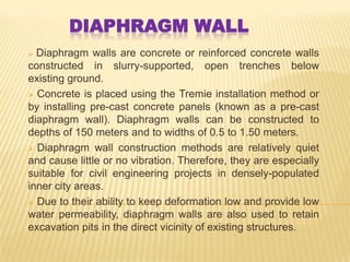
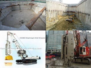
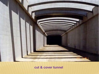
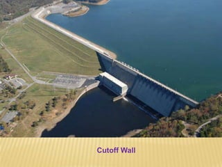
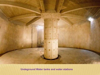
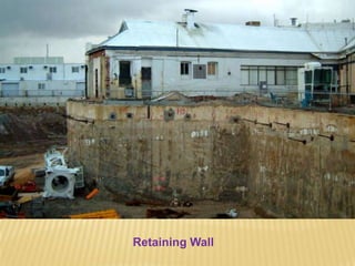
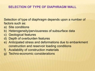

The document discusses diaphragm walls, which are concrete or reinforced concrete walls constructed below ground using a slurry-supported trench method. Diaphragm walls can reach depths of 150 meters and widths of 0.5-1.5 meters. They are constructed using tremie installation or pre-cast concrete panels. Diaphragm walls are suitable for urban construction due to their quiet installation and lack of vibration. The document discusses different types of diaphragm walls based on materials and functions, and provides details on their design, construction process, and material requirements.


