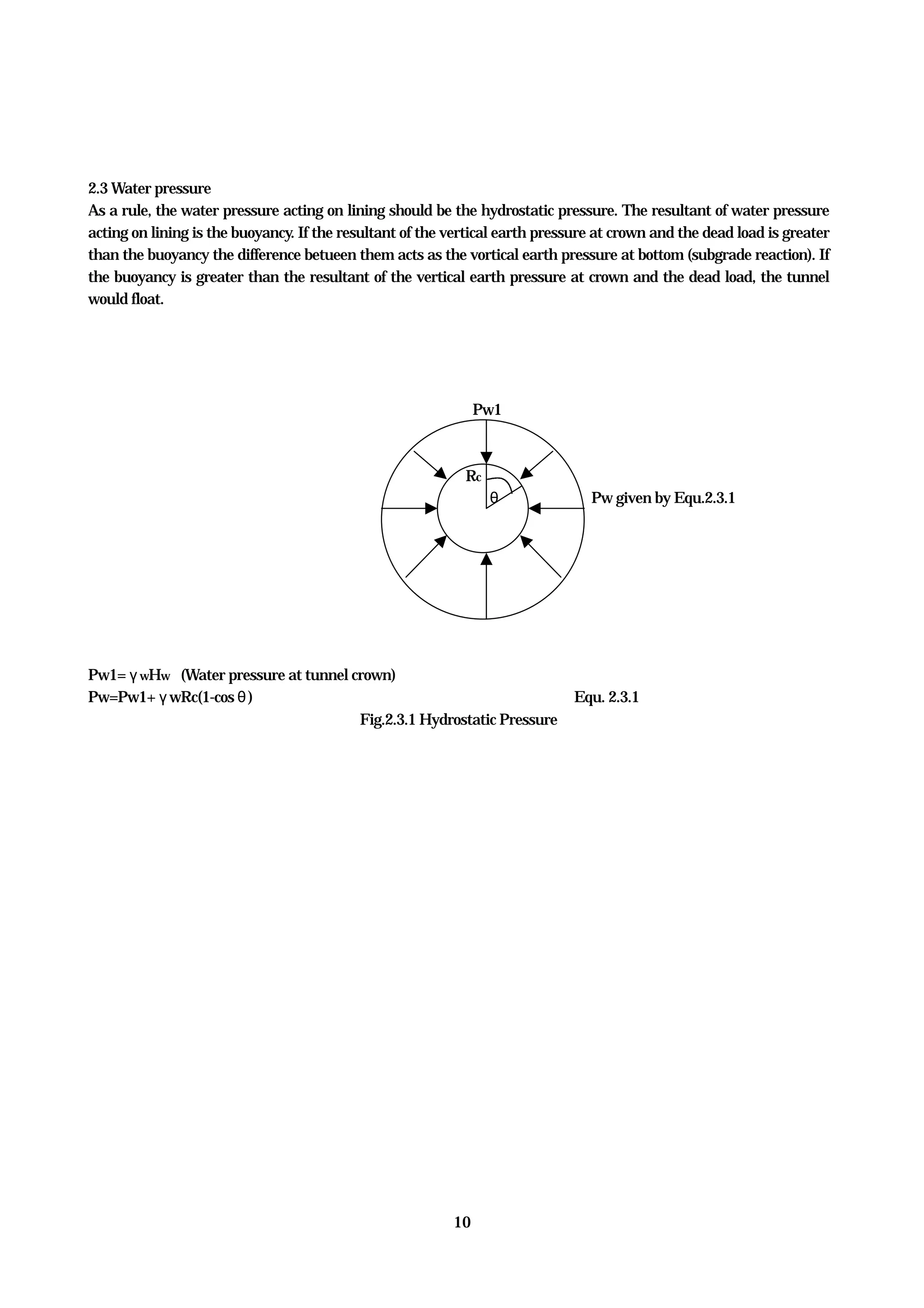
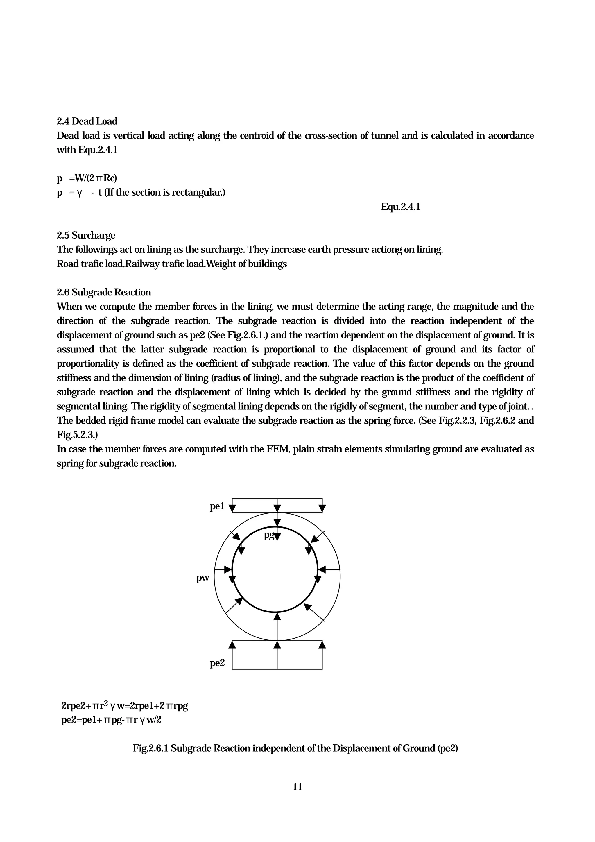
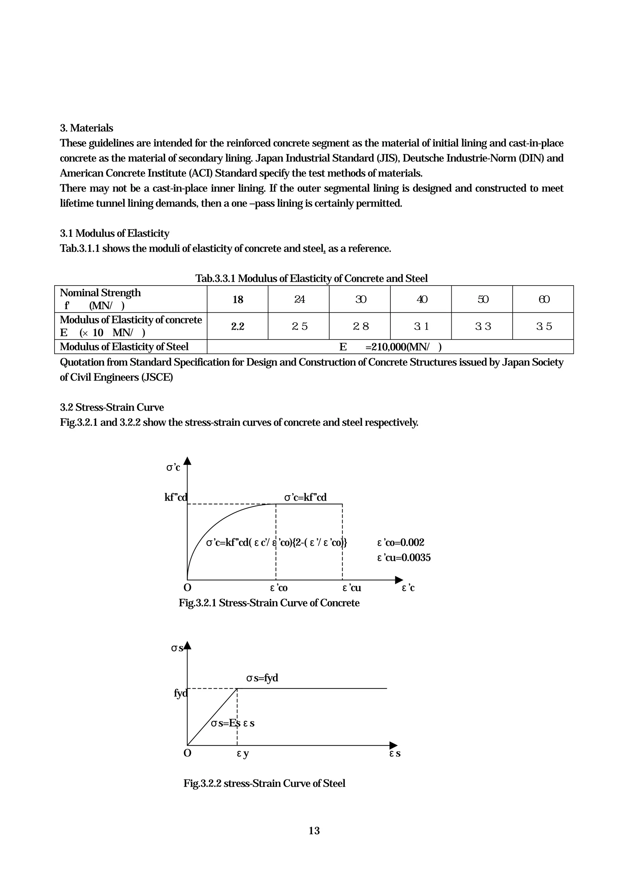
The document provides guidelines for designing shield tunnel linings, including:
- The guidelines were developed by the ITA Working Group from 1993-1999 to promote advances in shield tunnel design.
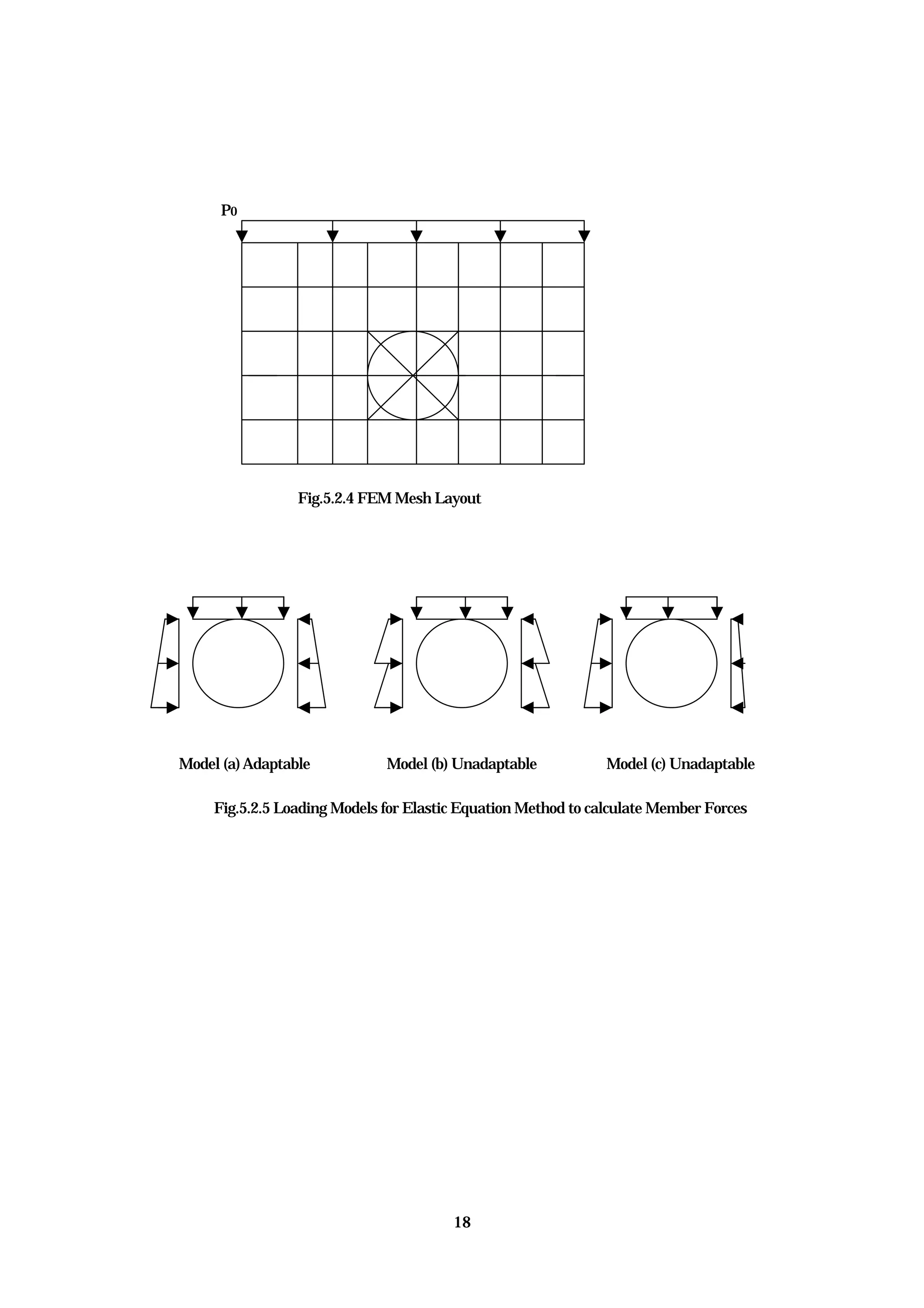
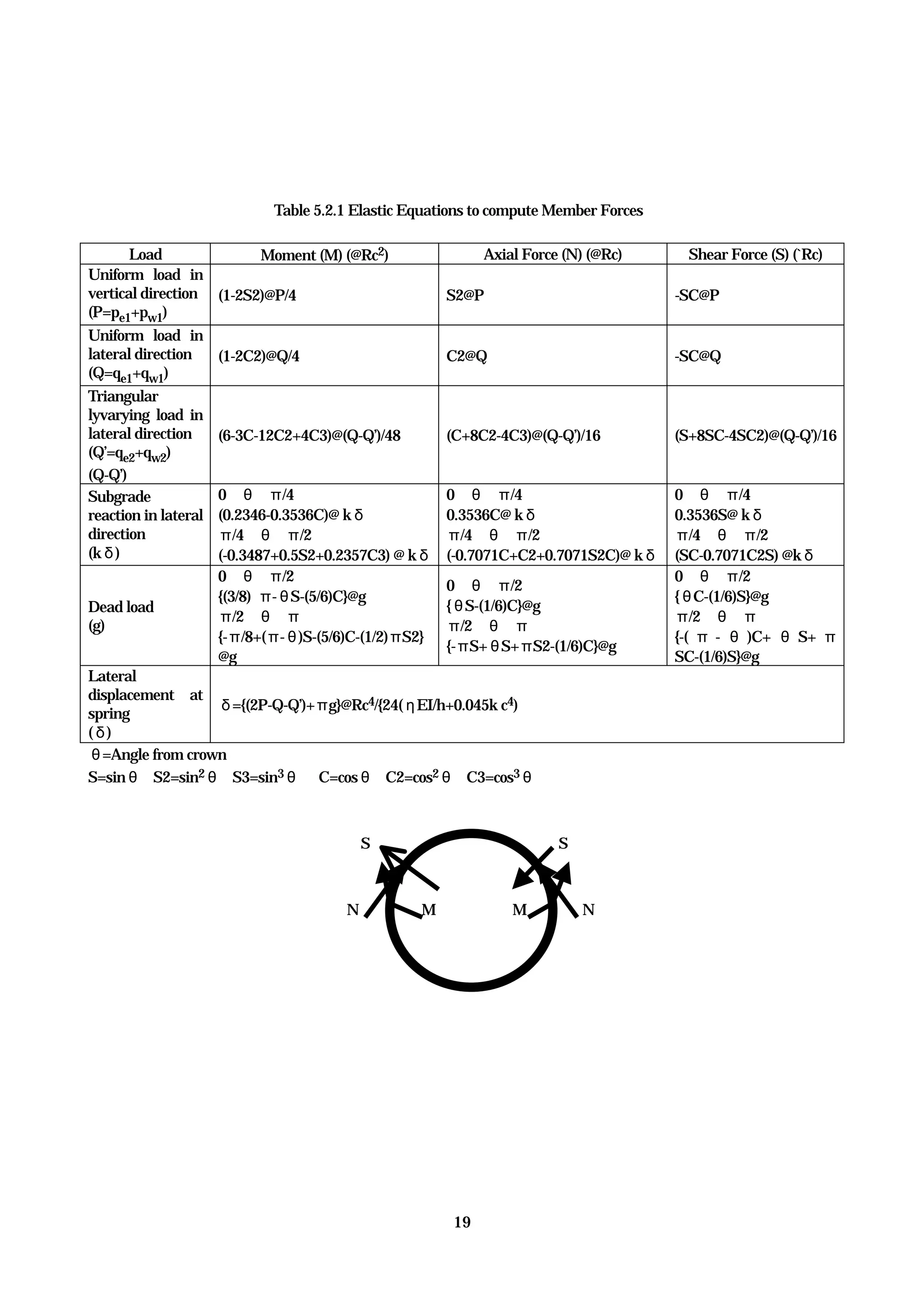
- Key aspects of shield tunnel lining design covered include deciding loads, material properties, structural analysis methods, safety checking, and construction details. Numerical modeling and analytical methods are recommended for analyzing member forces in the lining.


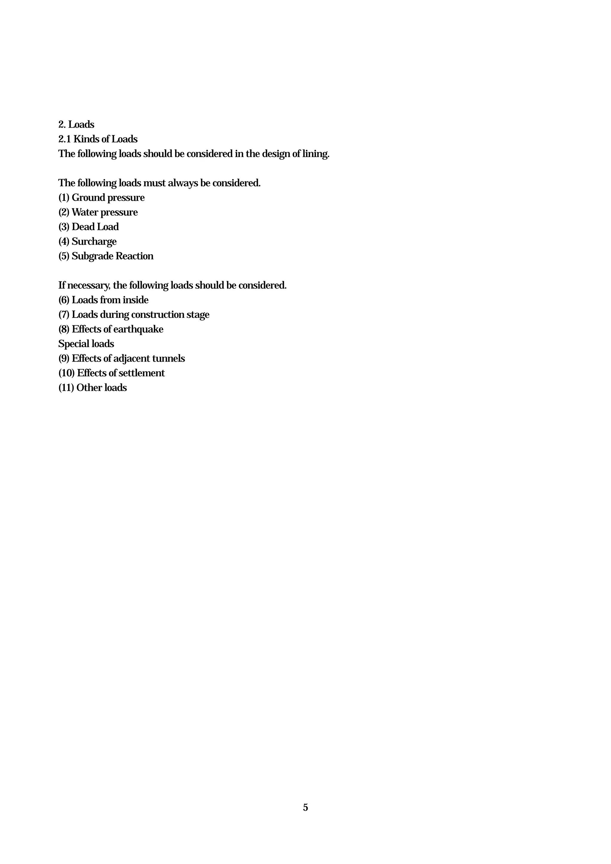

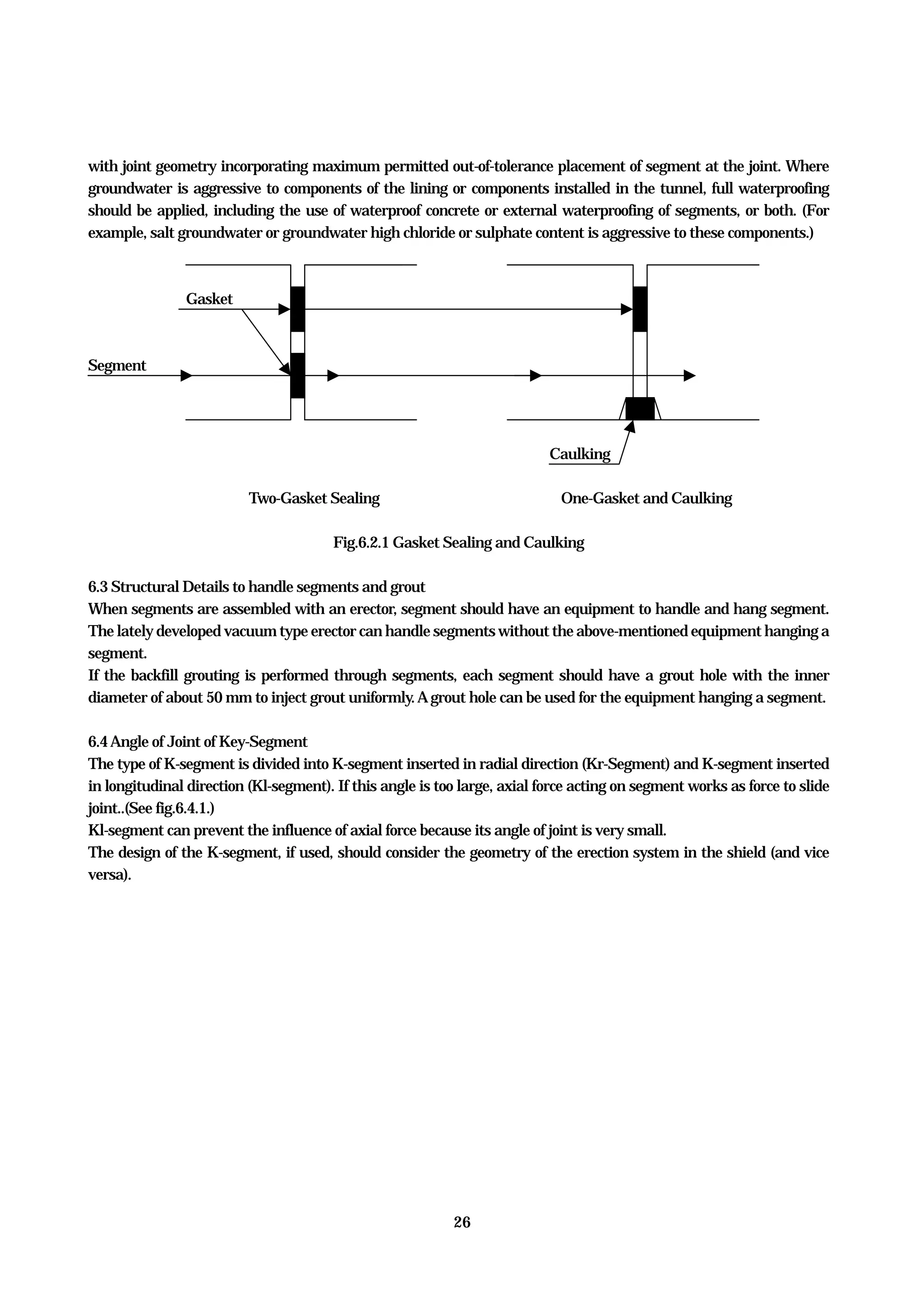
![7
h0=B1[1-C/B1γ)}{1-exp(-k0tan(φ)H/B1)]/K0tan(φ)+P0exp{-K0tan(φ)H/B1}/γ
B1=R0cot(π/8+φ/4)
Pe1=γh0 (if tunnel is located above groundwater table.)
Pe1=γ’h0 (if h0 ≦Hw)
Terzaghi's formula Formula 2.2.1
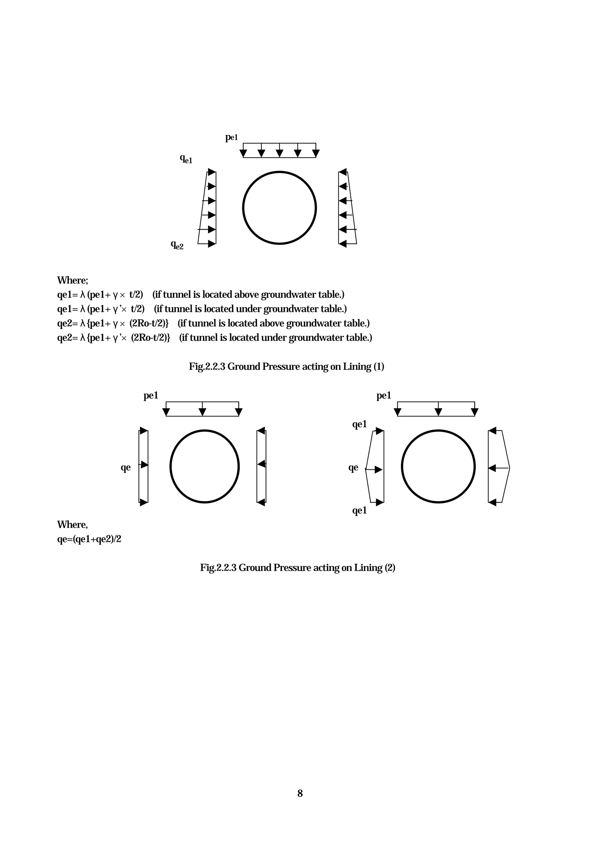
Where,
h0=Reduced earth pressure divided by unit weight of soil
K0=Ratio between lateral earth pressure and vertical earth pressure=1
Po
H
ho 2B1
π/4+φ/2
Do
Fig.2.2.2 Reduced Earth Pressure calculated by Terzaghi's formula](https://image.slidesharecdn.com/guidelines-160913165014/75/Guidelines-22-2048.jpg)