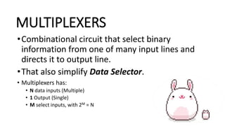
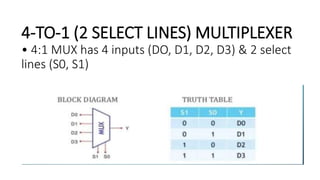
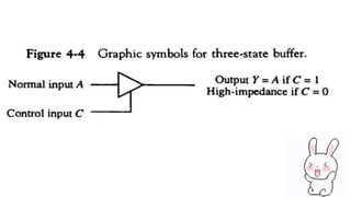
DECODER AND
MULTIPLEXER
CONTENT THAT BE COVERED:
• Decoder
• Example of binary decoder.
• Decoders: implementing function.
• Decoder with enable.
• Multiplexers
• Block diagram of multiplexer.
• Majority function using a Multiplexer.
• Types of lines in multiplexer.
• Three-state gates.
• Graphic symbol for a three-state Buffer.
WHAT IS DECODER?
DECODER
• A decoder is a combination logic circuit which has many input and
output lines.
• Therefore a decoder has “n” input lines and maximum “m” output
lines, where
• m=2n. When the decoder circuits is enable l, based on the
combination of
• input present, one of the 2n output lines will be active high.
• The decoder is also known as min-term generator or max-term
generator
EXAMPLE OF BINARY DECODER
DECODER : IMPLEMENTING
FUNCTION.
•Boolean function, in sum of min-terms form decoder
to generate the min-terms, and an OR gate to form
the sum.
•Any combinational circuit with n inputs and m outputs
can be implemented with an n:2n decoder with m OR
gates.
Decoders with Enable
A standard decoder typically has
an additional input called Enable.
Output is only generated when
the Enable input has value 1;
otherwise, all outputs are 0. Only
a small change in the
implementation is required: the
Enable input is fed into the AND
gates which produce the outputs.
WHAT IS MULTIPLEXER?
MULTIPLEXERS
•Combinational circuit that select binary
information from one of many input lines and
directs it to output line.
•That also simplify Data Selector.
• Multiplexers has:
• N data inputs (Multiple)
• 1 Output (Single)
• M select inputs, with 2M = N
BLOCK DIAGRAM OF MULTIPLEXER.
Implementing
Multiplexers
The implementation of a
multiplexer is straightforward,
and uses a decoder. Here is a 4-
1 multiplexer.
TYPES OF LINES IN MULTIPLEXER.
•2-to-1 (1 select lines)
•4-to-1 (2 select lines)
2-TO-1 (SELECT LINES) MULTIPLEXER
•Here 2:1 means 2 inputs and 1 output
4-TO-1 (2 SELECT LINES) MULTIPLEXER
• 4:1 MUX has 4 inputs (DO, D1, D2, D3) & 2 select
lines (S0, S1)
THREE-STATE GATES
• Multiplexer can be constructed with three-state gates. A three state
gates is a digital circuit that exhibits three state. Two of the states
are signal equivalent to logic 1&0 as a conventional gate. The third
state gates is a the high-impedance state that behaves like An open
circuit that means Output appears To disconnect and the circuit has
no logic significant.
• The most commonly used is the buffer gate.
REFERENCES
• slideserve.com
• slideshare.net
• https://m.youtube.com/watch?v=FKvnmxte98A
THE END

LOGIC DECODERS and MULTI.pptx

  • 1.
  • 2.
    CONTENT THAT BECOVERED: • Decoder • Example of binary decoder. • Decoders: implementing function. • Decoder with enable. • Multiplexers • Block diagram of multiplexer. • Majority function using a Multiplexer. • Types of lines in multiplexer. • Three-state gates. • Graphic symbol for a three-state Buffer.
  • 3.
  • 4.
    DECODER • A decoderis a combination logic circuit which has many input and output lines. • Therefore a decoder has “n” input lines and maximum “m” output lines, where • m=2n. When the decoder circuits is enable l, based on the combination of • input present, one of the 2n output lines will be active high. • The decoder is also known as min-term generator or max-term generator
  • 5.
  • 7.
    DECODER : IMPLEMENTING FUNCTION. •Booleanfunction, in sum of min-terms form decoder to generate the min-terms, and an OR gate to form the sum. •Any combinational circuit with n inputs and m outputs can be implemented with an n:2n decoder with m OR gates.
  • 10.
    Decoders with Enable Astandard decoder typically has an additional input called Enable. Output is only generated when the Enable input has value 1; otherwise, all outputs are 0. Only a small change in the implementation is required: the Enable input is fed into the AND gates which produce the outputs.
  • 11.
  • 12.
    MULTIPLEXERS •Combinational circuit thatselect binary information from one of many input lines and directs it to output line. •That also simplify Data Selector. • Multiplexers has: • N data inputs (Multiple) • 1 Output (Single) • M select inputs, with 2M = N
  • 13.
    BLOCK DIAGRAM OFMULTIPLEXER.
  • 14.
    Implementing Multiplexers The implementation ofa multiplexer is straightforward, and uses a decoder. Here is a 4- 1 multiplexer.
  • 15.
    TYPES OF LINESIN MULTIPLEXER. •2-to-1 (1 select lines) •4-to-1 (2 select lines)
  • 16.
    2-TO-1 (SELECT LINES)MULTIPLEXER •Here 2:1 means 2 inputs and 1 output
  • 17.
    4-TO-1 (2 SELECTLINES) MULTIPLEXER • 4:1 MUX has 4 inputs (DO, D1, D2, D3) & 2 select lines (S0, S1)
  • 18.
    THREE-STATE GATES • Multiplexercan be constructed with three-state gates. A three state gates is a digital circuit that exhibits three state. Two of the states are signal equivalent to logic 1&0 as a conventional gate. The third state gates is a the high-impedance state that behaves like An open circuit that means Output appears To disconnect and the circuit has no logic significant. • The most commonly used is the buffer gate.
  • 20.
    REFERENCES • slideserve.com • slideshare.net •https://m.youtube.com/watch?v=FKvnmxte98A
  • 21.