Downloaded 201 times
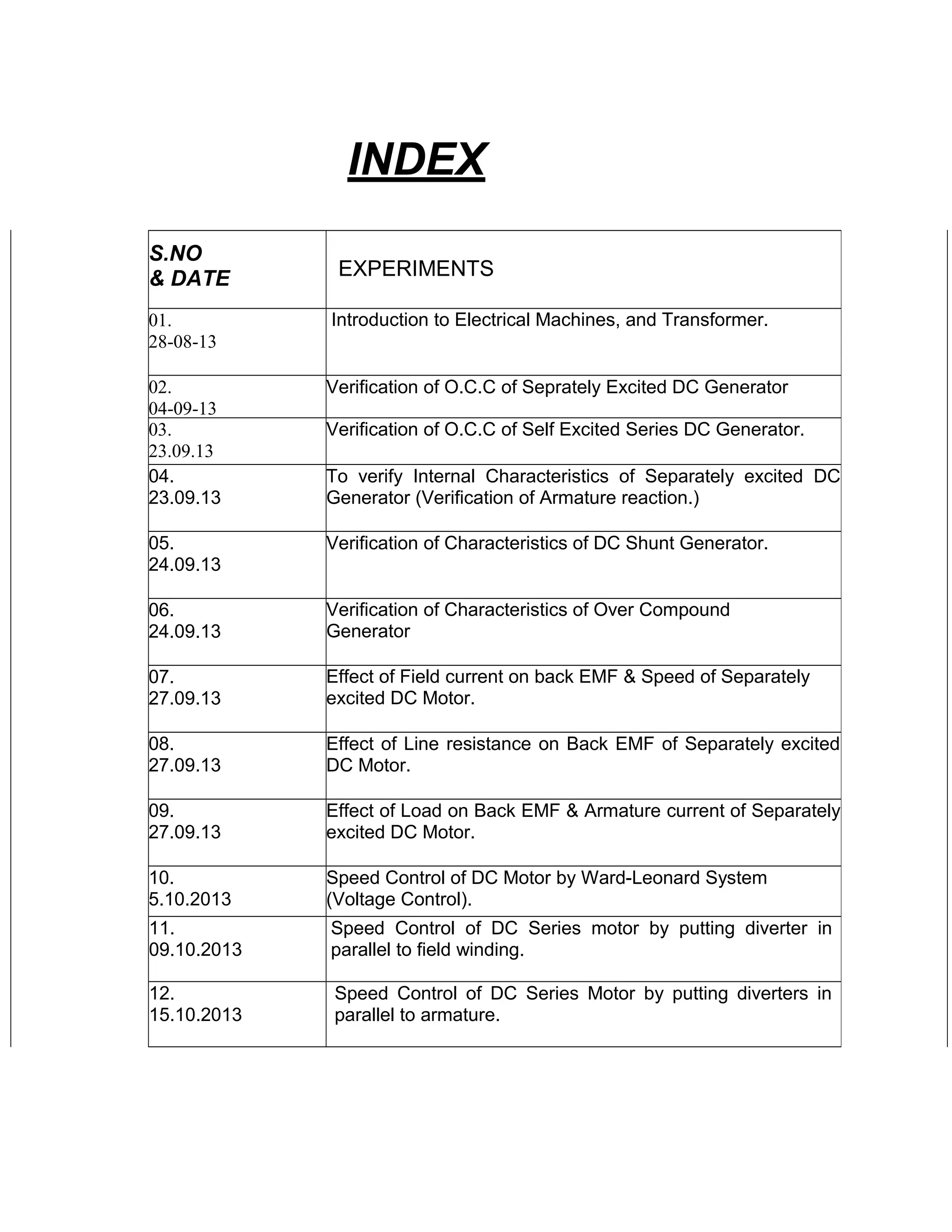
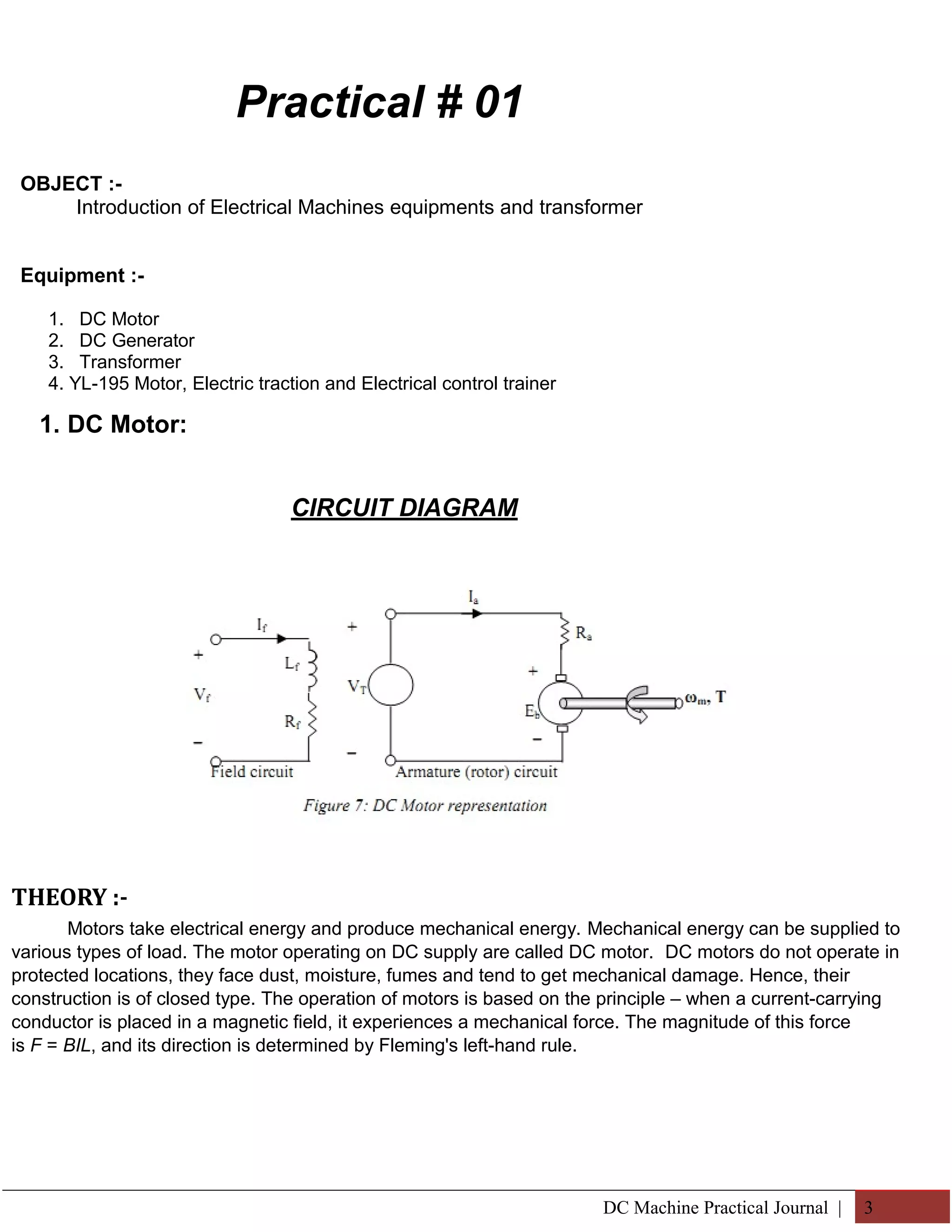
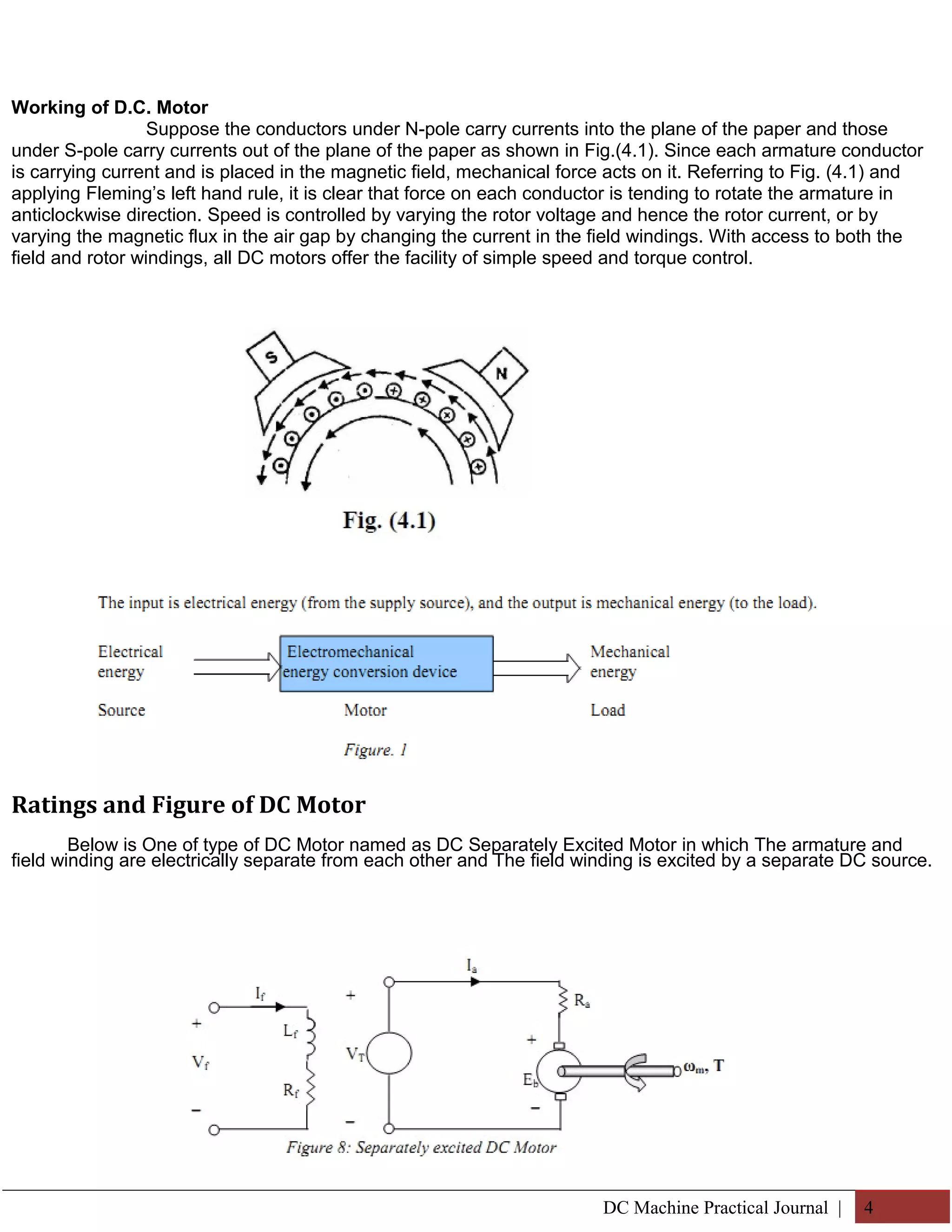
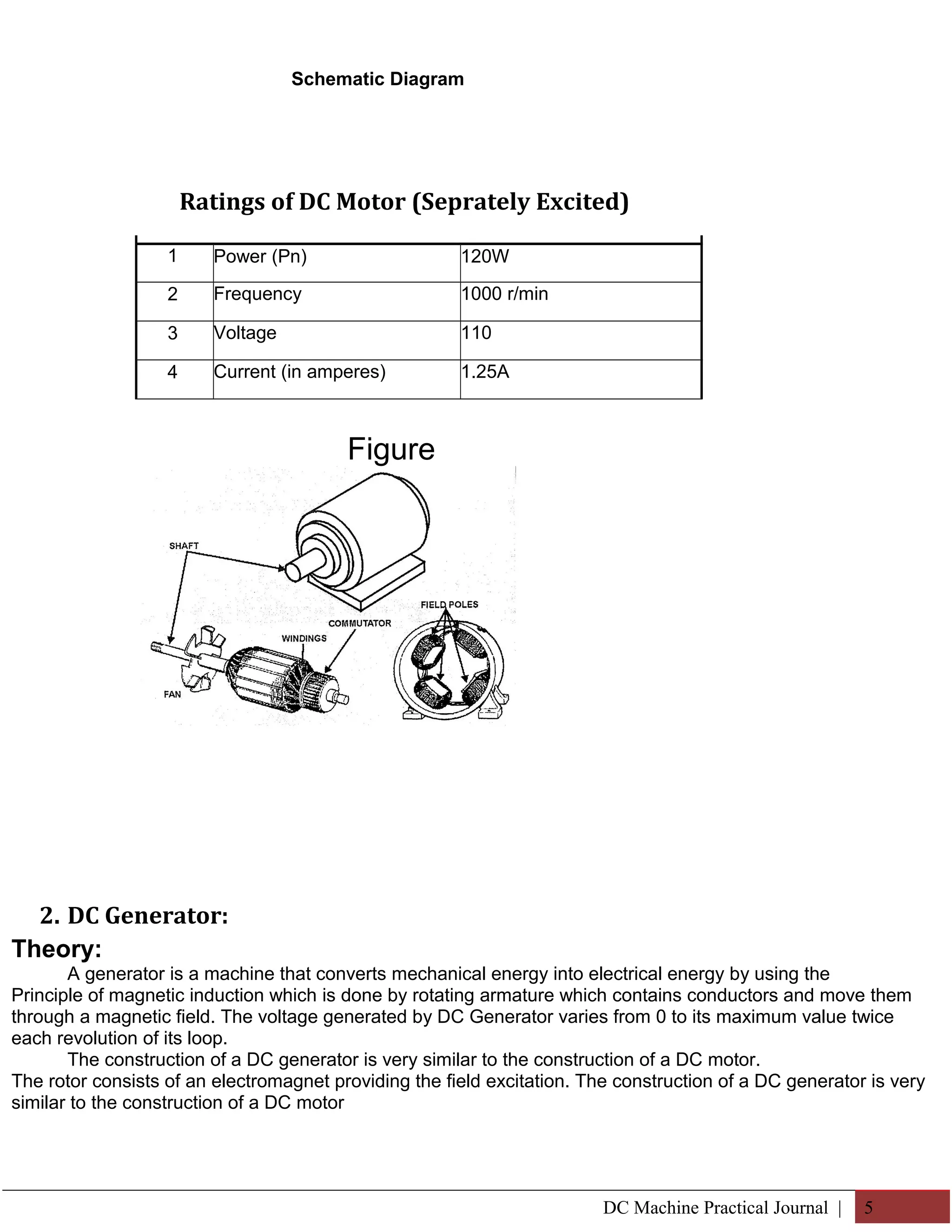
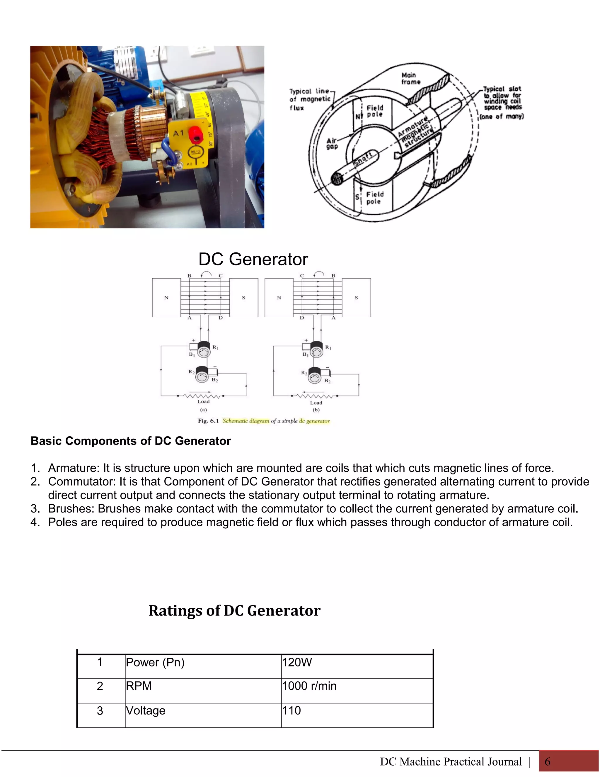
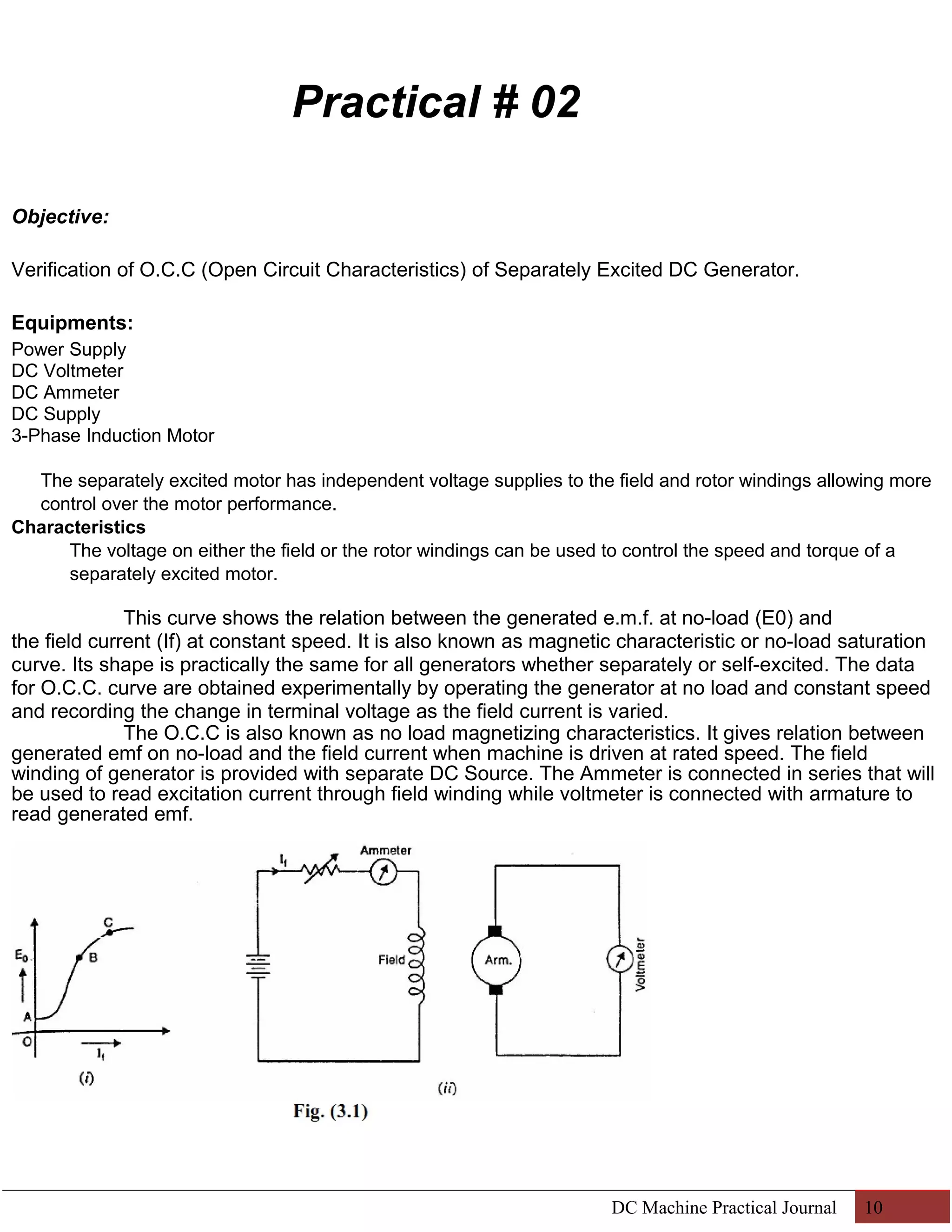

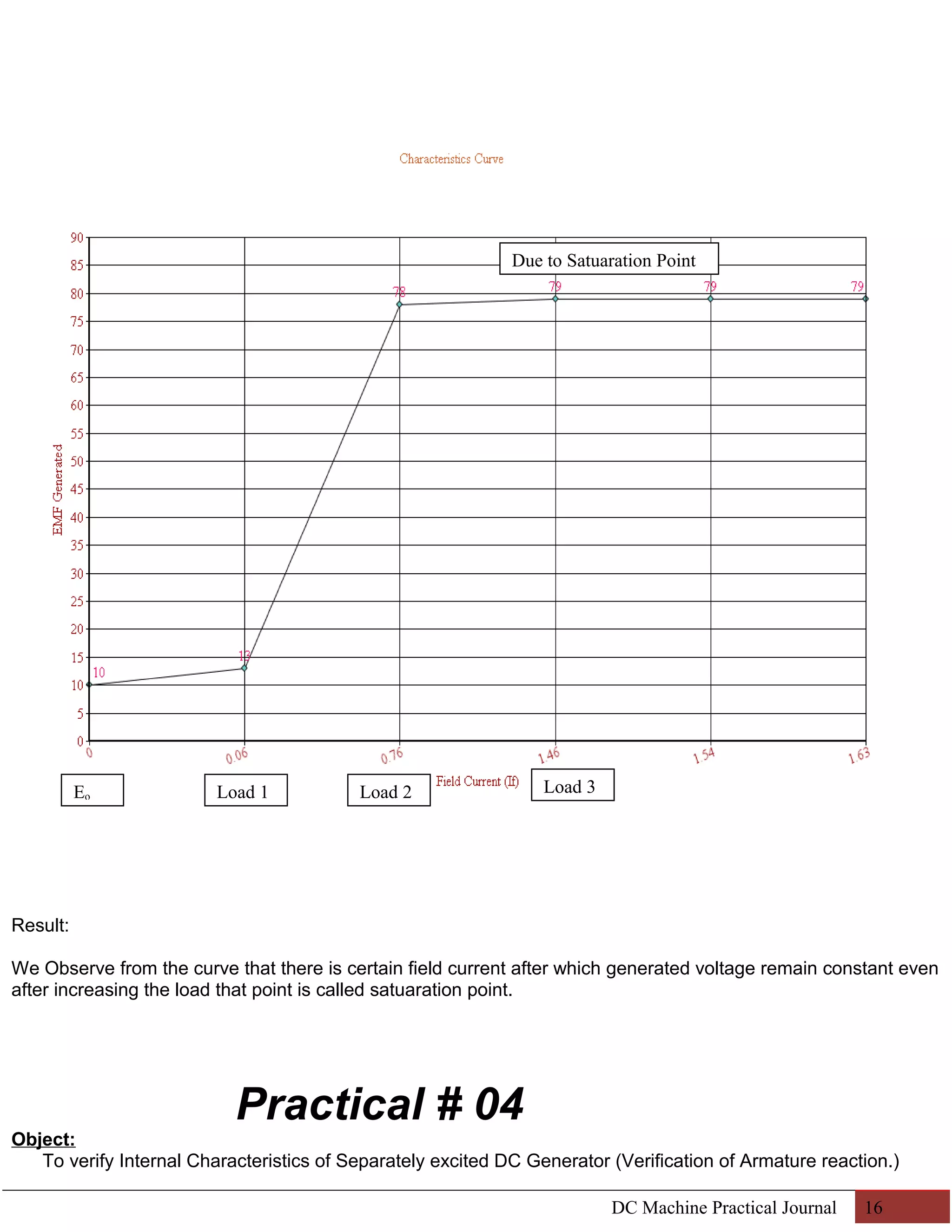
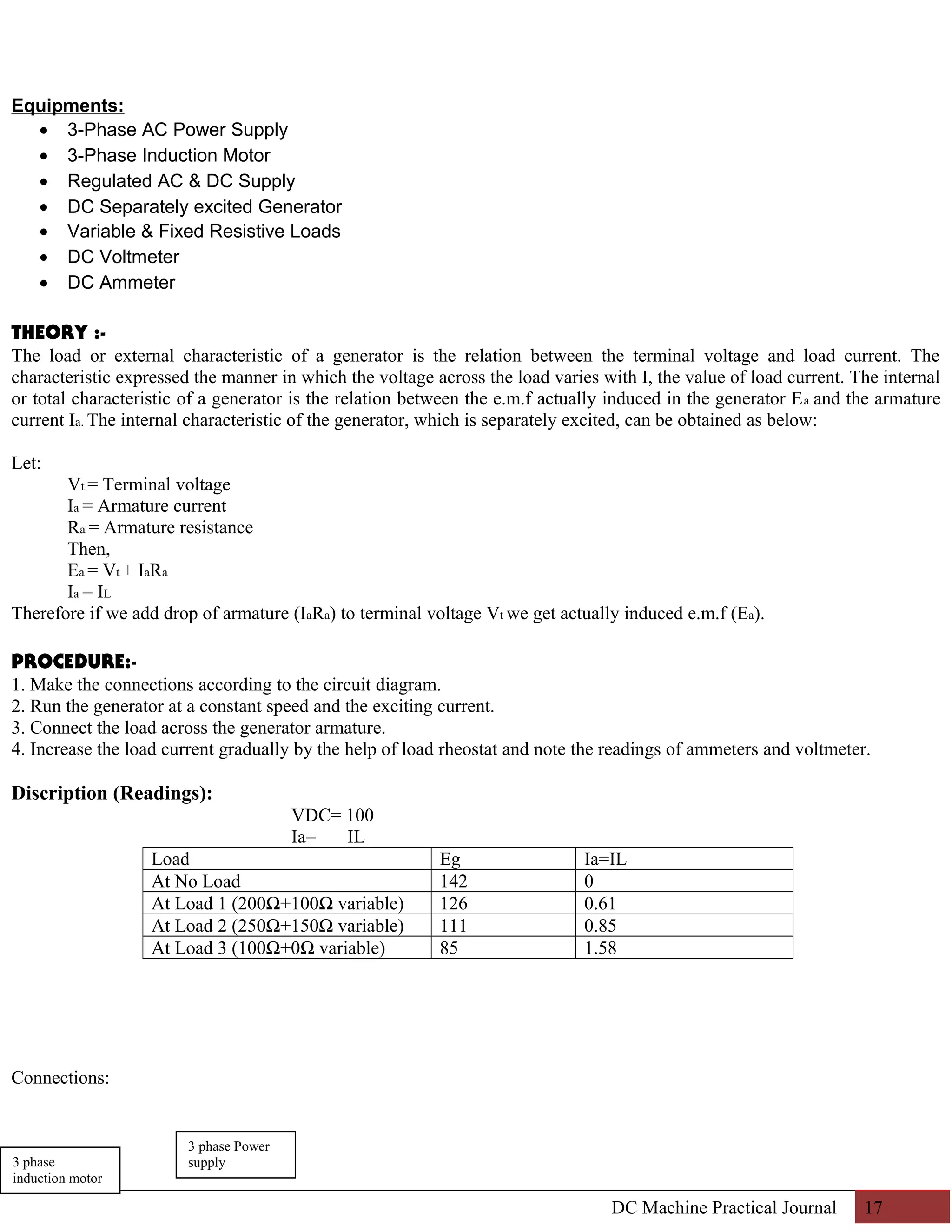
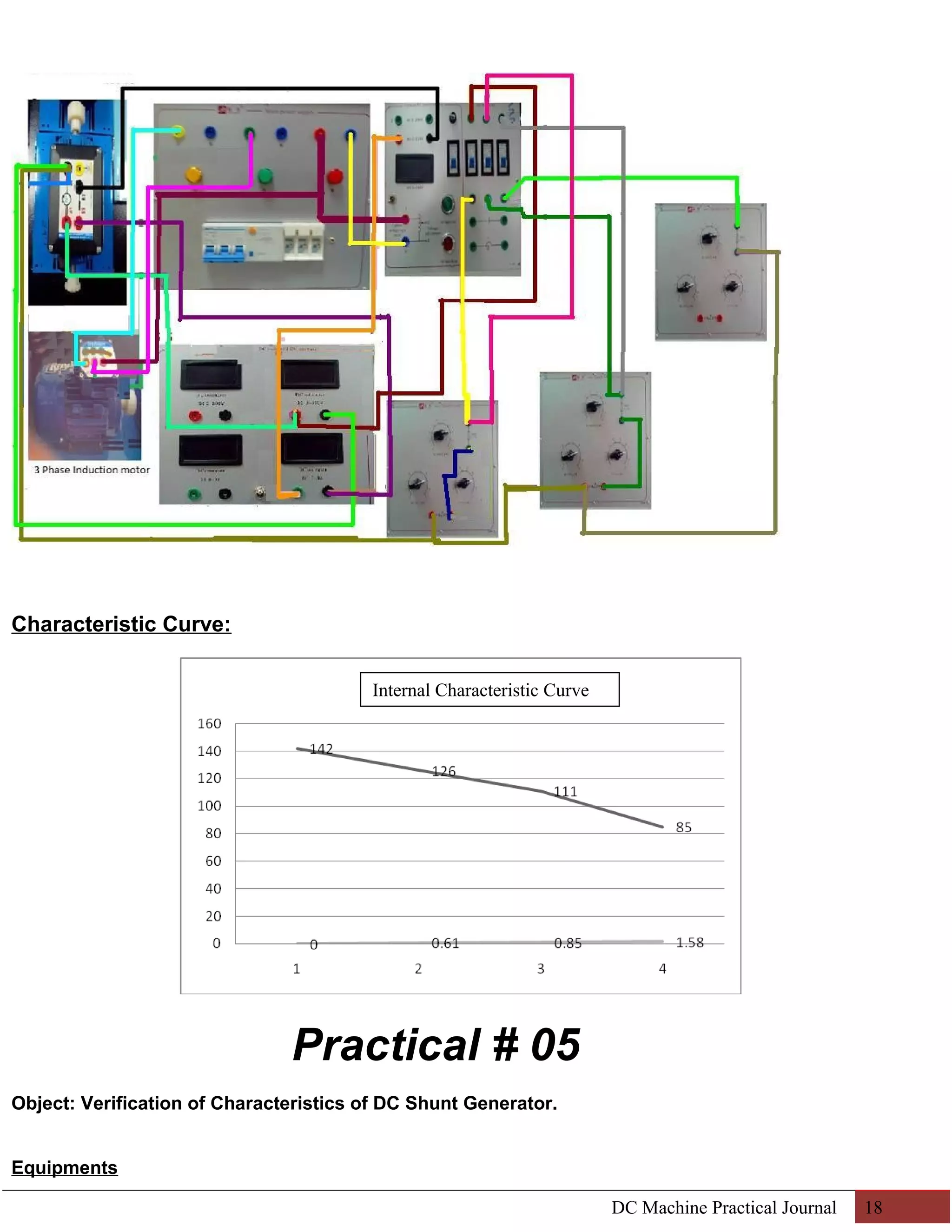

This document provides information about experiments conducted in an electrical machines lab at Mehran University of Engineering and Technology. It includes an index listing 12 experiments conducted between August and October on topics like DC generators, motors, and control systems. Practical 1 provides an introduction to electrical machine equipment like DC motors, generators, transformers, and control panels. It describes the components and operating principles. The document also includes circuit diagrams, readings tables and conclusions from experiments verifying open circuit characteristics of separately excited DC generators and self-excited series DC generators.