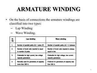
The document provides information on the construction, working principle, and types of transformers. It begins by explaining the necessity of transformers in electrical power systems for stepping up and down voltages. The key points are:
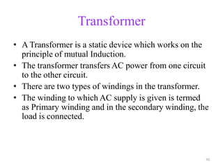
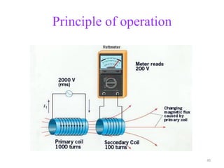
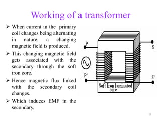
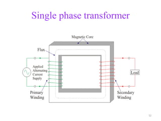
- Transformers transfer power between circuits through electromagnetic induction without changing frequency. They have a primary and secondary winding wound around an iron core.
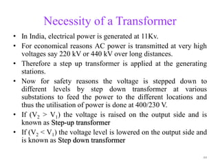
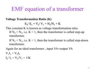
- Transformers can be used to step up or step down voltages depending on the ratio of turns in the primary and secondary windings. The voltage transformation ratio is equal to the ratio of turns.
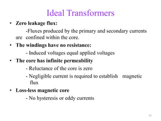
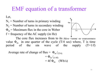
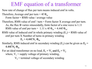
- An ideal transformer has zero resistance windings, infinite core permeability, and is lossless. The voltage induced in each winding is directly proportional to its turns and the rate