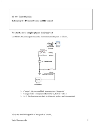
SlideShare a Scribd company logo
1 of 12
Download to read offline
Nalan Karunanayake 1
EC 350 - Control Systems
Laboratory 02 – DC motor Control and PID Control
Model a DC motor using the physical model approach
Use SIMULINK simscape to model the electromechanical system as follows,
 Change PSS-converter block parameter to A (Amperes).
 Change Model Configuration Parameter as, Solver-> ode15s
 RUN the simulation and observe the current produce and comment on it
Model the mechanical portion of the system as follows,
Nalan Karunanayake 2
 RE-RUN the model and observe the output current and comment on it.
Modified the simulation file as follows,
 Change PSS-simulink converter 1 parameter to RPM.
 RE-RUN the Simulink model again and observe the scope 1 and comment on it.
Nalan Karunanayake 3
Produce translational motion as follows,
 What does Wheel and Axle block do?
 RE-RUN the model again and observe the scope 1 and comment on it.
 Disconnect PSS Simulink converter 1 from port W of the Ideal Rotational Motion Sensor and
reconnect it with port A (change the PSS Simulink converter parameter to deg)
 RE-RUN the model and observe the scope 1 and comment on it.
 Change the spring rate of the Translation spring to 100 and 10, RE-RUN the model and observe
the output of the scope 1 and comment on it.
PID Control System
Introduction
Recall the open-loop transfer function of the DC Motor.
𝑃(𝑠) =
∅(𝑠)
𝑉(𝑠)
=
𝐾
𝑠((𝐽𝑠 + 𝑏)(𝐿𝑠 + 𝑅) + 𝐾2)
The structure of the control system has the form shown in the figure below.
Nalan Karunanayake 4
Transfer function for a PID controller has the following form.
𝐶(𝑠) = 𝐾 𝑝 +
𝐾𝑖
𝑠
+ 𝐾 𝑑 𝑠 =
𝐾 𝑑 𝑠2
+ 𝐾 𝑝 𝑠 + 𝐾𝑖
𝑠
A proportional controller ( ) will have the effect of reducing the rise time and will reduce but
never eliminate the steady-state error. An integral control ( ) will have the effect of eliminating
the steady-state error for a constant or step input, but it may make the transient response slower.
A derivative control ( ) will have the effect of increasing the stability of the system, reducing the
overshoot, and improving the transient response.
The effects of each of controller parameters, , , and on a closed-loop system are
summarized as in the table below.
Parameter Rise Time Overshoot Settling Time Steady State Error
Kp Decrease Increase Small Change Decrease
Ki Decrease Increase Increase Eliminate
Kd Small Change Decrease Decrease No Change
The structure of the control system has the form shown in the figure below.
Nalan Karunanayake 5
Transfer function for a PID controller has the following form.
𝐶(𝑠) = 𝐾 𝑝 +
𝐾𝑖
𝑠
+ 𝐾 𝑑 𝑠 =
𝐾 𝑑 𝑠2
+ 𝐾 𝑝 𝑠 + 𝐾𝑖
𝑠
Where = Proportional gain, = Integral gain and = Derivative gain
Use below coding to directly define a PID controller in MATLAB using the transfer function:
Kp = 1;
Ki = 1;
Kd = 1;
s = tf('s');
C = Kp + Ki/s + Kd*s
Alternatively MATLAB's pid controller object can be used to generate an equivalent continuous time
controller as follows:
C = pid(Kp, Ki, Kd);
1. Proportional control
The closed-loop transfer function of a system with a proportional controller is shown below
Use Matlab to answer below questions
Nalan Karunanayake 6
Questions
1.1 Draw a rough sketch of the response of the system to a step reference with different
values of Kp
1.2 Comment on the effect of increasing proportional gain on overshoot and settle time?
2. PD control
The closed-loop transfer function of the given system with a PD controller is shown below
Initially set the value of Kp = 300 and test derivative gain Kd value set to 10. Change your m-file to obtain
the step response of the above system with PD control.
Questions
2.1 Draw a rough sketch of the response of the system to a step reference with different
values of Kd.
2.2 Briefly explain the use of Proportional-Derivative Controller in a particular system?
Comment on the effect of increasing derivative gain (Kd) on overshoot and settle time?
3. PI control
The closed-loop transfer function of the given system with a PI controller is shown below
Initially set the value of Kp = 30 and test integral gain Ki value set to 70. Change your m-file to obtain the
step response of the above system with PI control.
Questions
3.1 Draw a rough sketch of the response of the system to a step reference with different
values of Ki.
3.2 Explain the effect of increasing Ki in the particular system?
Nalan Karunanayake 7
4. PID control
The closed-loop transfer function of the given system with a PID controller is shown below
Now modify the above m file as = 350, = 300, and = 50 to obtain the step response of the above
system with PID control.
Questions
4.1 Draw a rough sketch of the response of the system to a step reference with different
values of Kp, Ki and Kd?
 Use the Matlab command “stepinfo” to obtain the precise characteristics of the step response.
4.2 Comment on the effect of Kp, Ki and Kd parameters on the system?
PID control design with Control System Toolbox
Nalan Karunanayake 8
>> pidtool(sys)
 Change the controller type P, PI, PID and obtain the Step Plot and comment.
 From the Show Parameters, obtain the PID gains and characteristics of the system.
 Change the Response Time and Phase Margin and see what happened to the Step Plot.
Tune PID controller for a DC Motor in MATLAB SIMULINK
Consider an example of designing a PID controller for a dc motor. The model of a closed loop system
uses the new PID Controller block. This block generates a voltage signal driving the dc motor to track
desired shaft rotation speed. In addition to voltage, the dc motor subsystem takes torque disturbance as
an input, allowing us to simulate how well the controller rejects disturbances.
Open the CSlab2.slx
Nalan Karunanayake 9
The PID controller is a discrete-time controller running at 0.02 seconds (the red color shows the sampling
time in the model). Let’s now look at the dialog of the PID Controller block. In the upper half of the dialog
we specified basic configuration of the PID controller: type (PID, PI, PD, P, or I), time-domain, integration
methods, and sample time. In the lower part, we specified PID controller form and gains (shown at default
values).
Block documentation provides detailed information about the block and all its parameters.
Nalan Karunanayake 10
Check the scope of the PID block
PID Tuning
Our first task is to tune the PID controller. Pressing the “Tune…” button in the PID Controller block
dialog, we launch PID Tuner, which linearizes the model at the default operating point and automatically
determines PID controller gains to achieve reasonable performance and robustness based on linearized
plant model.
Nalan Karunanayake 11
Update the PID Tuner
Check the PID controller values again
Nalan Karunanayake 12
Then again RE-RUN the Simulink model and observe the PID scope and comment on it.
 How to make the system faster?
 What are the drawbacks of that method?

More Related Content

What's hot

Transformer single phase and three phase
Transformer single phase and three phaseTransformer single phase and three phase
Transformer single phase and three phaseDr.Raja Masood Larik
 
Single phase ac voltage controller
Single phase ac voltage controllerSingle phase ac voltage controller
Single phase ac voltage controllerSwati Tiwari
 
Invering and non inverting amplifiers
Invering and non inverting amplifiersInvering and non inverting amplifiers
Invering and non inverting amplifiersMuhammad Mohsin
 
Unit 1 Power System Stability
Unit 1 Power System Stability Unit 1 Power System Stability
Unit 1 Power System Stability SANTOSH GADEKAR
 
Bipolar Junction Transistor (BJT) DC and AC Analysis
Bipolar Junction Transistor (BJT) DC and AC AnalysisBipolar Junction Transistor (BJT) DC and AC Analysis
Bipolar Junction Transistor (BJT) DC and AC AnalysisJess Rangcasajo
 
A dual active bridge dc-dc converter for application in a smart user network
A dual active bridge dc-dc converter for application in a smart user networkA dual active bridge dc-dc converter for application in a smart user network
A dual active bridge dc-dc converter for application in a smart user networkAlessandro Burgio
 
Principles of Power Systems V.K Mehta Complete Book - Chapter 6
Principles of Power Systems V.K Mehta Complete Book - Chapter 6Principles of Power Systems V.K Mehta Complete Book - Chapter 6
Principles of Power Systems V.K Mehta Complete Book - Chapter 6Power System Operation
 
Transfer function, determination of transfer function in mechanical and elect...
Transfer function, determination of transfer function in mechanical and elect...Transfer function, determination of transfer function in mechanical and elect...
Transfer function, determination of transfer function in mechanical and elect...Saad Mohammad Araf
 
INTERLINE FLOW CONTROLLER
INTERLINE FLOW CONTROLLERINTERLINE FLOW CONTROLLER
INTERLINE FLOW CONTROLLERNitish NIT
 
Selection Of Circuit Breaker
Selection Of Circuit BreakerSelection Of Circuit Breaker
Selection Of Circuit BreakerRaviraj solanki
 
Speed Control of Synchronous Motor
Speed Control of Synchronous Motor Speed Control of Synchronous Motor
Speed Control of Synchronous Motor Ashutosh Jha
 
Principles of Power Systems V.K Mehta Complete Book - Chapter 7
Principles of Power Systems V.K Mehta Complete Book - Chapter 7Principles of Power Systems V.K Mehta Complete Book - Chapter 7
Principles of Power Systems V.K Mehta Complete Book - Chapter 7Power System Operation
 
Speed Torque Characteristics of BLDC Motor with Load Variations
Speed Torque Characteristics of BLDC Motor with Load VariationsSpeed Torque Characteristics of BLDC Motor with Load Variations
Speed Torque Characteristics of BLDC Motor with Load Variationsijtsrd
 
Vector control of pmsm
Vector control of pmsmVector control of pmsm
Vector control of pmsmMalarselvamV
 

What's hot (20)

Transformer single phase and three phase
Transformer single phase and three phaseTransformer single phase and three phase
Transformer single phase and three phase
 
Single phase ac voltage controller
Single phase ac voltage controllerSingle phase ac voltage controller
Single phase ac voltage controller
 
Pid controller
Pid controllerPid controller
Pid controller
 
Invering and non inverting amplifiers
Invering and non inverting amplifiersInvering and non inverting amplifiers
Invering and non inverting amplifiers
 
Fault analysis using z bus
Fault analysis using z busFault analysis using z bus
Fault analysis using z bus
 
Plc notes
Plc notesPlc notes
Plc notes
 
Unit 1 Power System Stability
Unit 1 Power System Stability Unit 1 Power System Stability
Unit 1 Power System Stability
 
Bipolar Junction Transistor (BJT) DC and AC Analysis
Bipolar Junction Transistor (BJT) DC and AC AnalysisBipolar Junction Transistor (BJT) DC and AC Analysis
Bipolar Junction Transistor (BJT) DC and AC Analysis
 
A dual active bridge dc-dc converter for application in a smart user network
A dual active bridge dc-dc converter for application in a smart user networkA dual active bridge dc-dc converter for application in a smart user network
A dual active bridge dc-dc converter for application in a smart user network
 
Principles of Power Systems V.K Mehta Complete Book - Chapter 6
Principles of Power Systems V.K Mehta Complete Book - Chapter 6Principles of Power Systems V.K Mehta Complete Book - Chapter 6
Principles of Power Systems V.K Mehta Complete Book - Chapter 6
 
Transfer function, determination of transfer function in mechanical and elect...
Transfer function, determination of transfer function in mechanical and elect...Transfer function, determination of transfer function in mechanical and elect...
Transfer function, determination of transfer function in mechanical and elect...
 
Per unit analysis
Per unit analysisPer unit analysis
Per unit analysis
 
INTERLINE FLOW CONTROLLER
INTERLINE FLOW CONTROLLERINTERLINE FLOW CONTROLLER
INTERLINE FLOW CONTROLLER
 
Selection Of Circuit Breaker
Selection Of Circuit BreakerSelection Of Circuit Breaker
Selection Of Circuit Breaker
 
Speed Control of Synchronous Motor
Speed Control of Synchronous Motor Speed Control of Synchronous Motor
Speed Control of Synchronous Motor
 
Principles of Power Systems V.K Mehta Complete Book - Chapter 7
Principles of Power Systems V.K Mehta Complete Book - Chapter 7Principles of Power Systems V.K Mehta Complete Book - Chapter 7
Principles of Power Systems V.K Mehta Complete Book - Chapter 7
 
Flyback converter
Flyback converterFlyback converter
Flyback converter
 
Speed Torque Characteristics of BLDC Motor with Load Variations
Speed Torque Characteristics of BLDC Motor with Load VariationsSpeed Torque Characteristics of BLDC Motor with Load Variations
Speed Torque Characteristics of BLDC Motor with Load Variations
 
Vector control of pmsm
Vector control of pmsmVector control of pmsm
Vector control of pmsm
 
Phasor Measurement Unit (PMU)
 Phasor Measurement Unit (PMU) Phasor Measurement Unit (PMU)
Phasor Measurement Unit (PMU)
 

Viewers also liked

control system Lab 01-introduction to transfer functions
control system Lab 01-introduction to transfer functionscontrol system Lab 01-introduction to transfer functions
control system Lab 01-introduction to transfer functionsnalan karunanayake
 
90981041 control-system-lab-manual
90981041 control-system-lab-manual90981041 control-system-lab-manual
90981041 control-system-lab-manualGopinath.B.L Naidu
 
CONTROL SYSTEM LAB MANUAL
CONTROL SYSTEM LAB MANUALCONTROL SYSTEM LAB MANUAL
CONTROL SYSTEM LAB MANUALPRINCE SHARMA
 
Btl control system-lab-manual-10 eel68
Btl control system-lab-manual-10 eel68Btl control system-lab-manual-10 eel68
Btl control system-lab-manual-10 eel68Gopinath.B.L Naidu
 
Control Systems Lab 2
Control Systems Lab 2Control Systems Lab 2
Control Systems Lab 2Julia London
 
Control systems engineering. by i.j. nagrath
Control systems engineering. by i.j. nagrathControl systems engineering. by i.j. nagrath
Control systems engineering. by i.j. nagrathSri Harsha
 
An Enhanced Computer Vision Based Hand Movement Capturing System with Stereo ...
An Enhanced Computer Vision Based Hand Movement Capturing System with Stereo ...An Enhanced Computer Vision Based Hand Movement Capturing System with Stereo ...
An Enhanced Computer Vision Based Hand Movement Capturing System with Stereo ...CSCJournals
 
196444650 ee-2257-control-system-lab-manual
196444650 ee-2257-control-system-lab-manual196444650 ee-2257-control-system-lab-manual
196444650 ee-2257-control-system-lab-manualhomeworkping3
 
Power System Simulation Laboratory Manual
Power System Simulation Laboratory Manual Power System Simulation Laboratory Manual
Power System Simulation Laboratory Manual Santhosh Kumar
 
Project Stuff Real cool
Project Stuff Real coolProject Stuff Real cool
Project Stuff Real coolJulia London
 
Lag Compensator
Lag CompensatorLag Compensator
Lag CompensatorIslam Naqi
 
POWER SYSTEM SIMULATION LAB-1 MANUAL (ELECTRICAL - POWER SYSTEM ENGINEERING )
POWER SYSTEM SIMULATION LAB-1 MANUAL (ELECTRICAL - POWER SYSTEM ENGINEERING )POWER SYSTEM SIMULATION LAB-1 MANUAL (ELECTRICAL - POWER SYSTEM ENGINEERING )
POWER SYSTEM SIMULATION LAB-1 MANUAL (ELECTRICAL - POWER SYSTEM ENGINEERING )Mathankumar S
 
Lab manual psd v sem experiment no 7
Lab manual psd v sem experiment no 7Lab manual psd v sem experiment no 7
Lab manual psd v sem experiment no 7Sachin Airan
 
Dynamic modelling of dc motor drive
Dynamic modelling of dc motor driveDynamic modelling of dc motor drive
Dynamic modelling of dc motor drivevishalgohel12195
 

Viewers also liked (20)

control system Lab 01-introduction to transfer functions
control system Lab 01-introduction to transfer functionscontrol system Lab 01-introduction to transfer functions
control system Lab 01-introduction to transfer functions
 
90981041 control-system-lab-manual
90981041 control-system-lab-manual90981041 control-system-lab-manual
90981041 control-system-lab-manual
 
CONTROL SYSTEM LAB MANUAL
CONTROL SYSTEM LAB MANUALCONTROL SYSTEM LAB MANUAL
CONTROL SYSTEM LAB MANUAL
 
Btl control system-lab-manual-10 eel68
Btl control system-lab-manual-10 eel68Btl control system-lab-manual-10 eel68
Btl control system-lab-manual-10 eel68
 
Control Systems Lab 2
Control Systems Lab 2Control Systems Lab 2
Control Systems Lab 2
 
Lead-lag controller
Lead-lag controllerLead-lag controller
Lead-lag controller
 
Control system
Control systemControl system
Control system
 
Control systems engineering. by i.j. nagrath
Control systems engineering. by i.j. nagrathControl systems engineering. by i.j. nagrath
Control systems engineering. by i.j. nagrath
 
An Enhanced Computer Vision Based Hand Movement Capturing System with Stereo ...
An Enhanced Computer Vision Based Hand Movement Capturing System with Stereo ...An Enhanced Computer Vision Based Hand Movement Capturing System with Stereo ...
An Enhanced Computer Vision Based Hand Movement Capturing System with Stereo ...
 
196444650 ee-2257-control-system-lab-manual
196444650 ee-2257-control-system-lab-manual196444650 ee-2257-control-system-lab-manual
196444650 ee-2257-control-system-lab-manual
 
LINAC 4 – Control System Design (small)
LINAC 4 – Control System Design (small)LINAC 4 – Control System Design (small)
LINAC 4 – Control System Design (small)
 
Power System Simulation Laboratory Manual
Power System Simulation Laboratory Manual Power System Simulation Laboratory Manual
Power System Simulation Laboratory Manual
 
Project Stuff Real cool
Project Stuff Real coolProject Stuff Real cool
Project Stuff Real cool
 
Dc machine practical
Dc machine practical Dc machine practical
Dc machine practical
 
Mini Project- Torque Control of a DC Motor
Mini Project- Torque Control of a DC MotorMini Project- Torque Control of a DC Motor
Mini Project- Torque Control of a DC Motor
 
Bode diagram
Bode diagramBode diagram
Bode diagram
 
Lag Compensator
Lag CompensatorLag Compensator
Lag Compensator
 
POWER SYSTEM SIMULATION LAB-1 MANUAL (ELECTRICAL - POWER SYSTEM ENGINEERING )
POWER SYSTEM SIMULATION LAB-1 MANUAL (ELECTRICAL - POWER SYSTEM ENGINEERING )POWER SYSTEM SIMULATION LAB-1 MANUAL (ELECTRICAL - POWER SYSTEM ENGINEERING )
POWER SYSTEM SIMULATION LAB-1 MANUAL (ELECTRICAL - POWER SYSTEM ENGINEERING )
 
Lab manual psd v sem experiment no 7
Lab manual psd v sem experiment no 7Lab manual psd v sem experiment no 7
Lab manual psd v sem experiment no 7
 
Dynamic modelling of dc motor drive
Dynamic modelling of dc motor driveDynamic modelling of dc motor drive
Dynamic modelling of dc motor drive
 

Similar to control system lab 02 - PID tuning

Control tutorials for matlab and simulink introduction pid controller desig...
Control tutorials for matlab and simulink   introduction pid controller desig...Control tutorials for matlab and simulink   introduction pid controller desig...
Control tutorials for matlab and simulink introduction pid controller desig...ssuser27c61e
 
Analysis and Design of PID controller with control parameters in MATLAB and S...
Analysis and Design of PID controller with control parameters in MATLAB and S...Analysis and Design of PID controller with control parameters in MATLAB and S...
Analysis and Design of PID controller with control parameters in MATLAB and S...MIbrar4
 
Design of imc based controller for industrial purpose
Design of imc based controller for industrial purposeDesign of imc based controller for industrial purpose
Design of imc based controller for industrial purpose375ankit
 
179529572-ROOT-LOCUS-Control-system-Design-ppt.ppt
179529572-ROOT-LOCUS-Control-system-Design-ppt.ppt179529572-ROOT-LOCUS-Control-system-Design-ppt.ppt
179529572-ROOT-LOCUS-Control-system-Design-ppt.pptTaraGonzales5
 
Iaetsd design of fuzzy self-tuned load frequency controller for power system
Iaetsd design of fuzzy self-tuned load frequency controller for power systemIaetsd design of fuzzy self-tuned load frequency controller for power system
Iaetsd design of fuzzy self-tuned load frequency controller for power systemIaetsd Iaetsd
 
Modeling, simulation and control of a robotic arm
Modeling, simulation and control of a robotic armModeling, simulation and control of a robotic arm
Modeling, simulation and control of a robotic armcesarportilla8
 
Speed control of dc motor using relay feedback tuned pi
Speed control of dc motor using relay feedback tuned piSpeed control of dc motor using relay feedback tuned pi
Speed control of dc motor using relay feedback tuned piAlexander Decker
 
Real-time PID control of an inverted pendulum
Real-time PID control of an inverted pendulumReal-time PID control of an inverted pendulum
Real-time PID control of an inverted pendulumFrancesco Corucci
 
Analysis and Design of Conventional Controller for Speed Control of DC Motor ...
Analysis and Design of Conventional Controller for Speed Control of DC Motor ...Analysis and Design of Conventional Controller for Speed Control of DC Motor ...
Analysis and Design of Conventional Controller for Speed Control of DC Motor ...IJERA Editor
 
Raymond.Brunkow-Project-EEL-3657-Sp15
Raymond.Brunkow-Project-EEL-3657-Sp15Raymond.Brunkow-Project-EEL-3657-Sp15
Raymond.Brunkow-Project-EEL-3657-Sp15Raymond Brunkow
 
Optimal and pid controller for controlling camera’s position in unmanned aeri...
Optimal and pid controller for controlling camera’s position in unmanned aeri...Optimal and pid controller for controlling camera’s position in unmanned aeri...
Optimal and pid controller for controlling camera’s position in unmanned aeri...Zac Darcy
 
Aifcraft pitch
Aifcraft pitchAifcraft pitch
Aifcraft pitchmbilal2792
 
Unity Feedback PD Controller Design for an Electronic Throttle Body
Unity Feedback PD Controller Design for an Electronic Throttle BodyUnity Feedback PD Controller Design for an Electronic Throttle Body
Unity Feedback PD Controller Design for an Electronic Throttle BodySteven Ernst, PE
 
Disturbance Rejection with a Highly Oscillating Second-Order Process, Part I...
Disturbance Rejection with a Highly Oscillating Second-Order  Process, Part I...Disturbance Rejection with a Highly Oscillating Second-Order  Process, Part I...
Disturbance Rejection with a Highly Oscillating Second-Order Process, Part I...Scientific Review SR
 
Process Control Final Report
Process Control Final ReportProcess Control Final Report
Process Control Final ReportLogan Williamson
 
Optimal and Pid Controller for Controlling Camera's Position InUnmanned Aeria...
Optimal and Pid Controller for Controlling Camera's Position InUnmanned Aeria...Optimal and Pid Controller for Controlling Camera's Position InUnmanned Aeria...
Optimal and Pid Controller for Controlling Camera's Position InUnmanned Aeria...Zac Darcy
 

Similar to control system lab 02 - PID tuning (20)

Control tutorials for matlab and simulink introduction pid controller desig...
Control tutorials for matlab and simulink   introduction pid controller desig...Control tutorials for matlab and simulink   introduction pid controller desig...
Control tutorials for matlab and simulink introduction pid controller desig...
 
Analysis and Design of PID controller with control parameters in MATLAB and S...
Analysis and Design of PID controller with control parameters in MATLAB and S...Analysis and Design of PID controller with control parameters in MATLAB and S...
Analysis and Design of PID controller with control parameters in MATLAB and S...
 
air craft Pitch
air craft Pitchair craft Pitch
air craft Pitch
 
1578385.ppt
1578385.ppt1578385.ppt
1578385.ppt
 
Design of imc based controller for industrial purpose
Design of imc based controller for industrial purposeDesign of imc based controller for industrial purpose
Design of imc based controller for industrial purpose
 
179529572-ROOT-LOCUS-Control-system-Design-ppt.ppt
179529572-ROOT-LOCUS-Control-system-Design-ppt.ppt179529572-ROOT-LOCUS-Control-system-Design-ppt.ppt
179529572-ROOT-LOCUS-Control-system-Design-ppt.ppt
 
Iaetsd design of fuzzy self-tuned load frequency controller for power system
Iaetsd design of fuzzy self-tuned load frequency controller for power systemIaetsd design of fuzzy self-tuned load frequency controller for power system
Iaetsd design of fuzzy self-tuned load frequency controller for power system
 
Modeling, simulation and control of a robotic arm
Modeling, simulation and control of a robotic armModeling, simulation and control of a robotic arm
Modeling, simulation and control of a robotic arm
 
Speed control of dc motor using relay feedback tuned pi
Speed control of dc motor using relay feedback tuned piSpeed control of dc motor using relay feedback tuned pi
Speed control of dc motor using relay feedback tuned pi
 
Real-time PID control of an inverted pendulum
Real-time PID control of an inverted pendulumReal-time PID control of an inverted pendulum
Real-time PID control of an inverted pendulum
 
Analysis and Design of Conventional Controller for Speed Control of DC Motor ...
Analysis and Design of Conventional Controller for Speed Control of DC Motor ...Analysis and Design of Conventional Controller for Speed Control of DC Motor ...
Analysis and Design of Conventional Controller for Speed Control of DC Motor ...
 
Raymond.Brunkow-Project-EEL-3657-Sp15
Raymond.Brunkow-Project-EEL-3657-Sp15Raymond.Brunkow-Project-EEL-3657-Sp15
Raymond.Brunkow-Project-EEL-3657-Sp15
 
Optimal and pid controller for controlling camera’s position in unmanned aeri...
Optimal and pid controller for controlling camera’s position in unmanned aeri...Optimal and pid controller for controlling camera’s position in unmanned aeri...
Optimal and pid controller for controlling camera’s position in unmanned aeri...
 
Aifcraft pitch
Aifcraft pitchAifcraft pitch
Aifcraft pitch
 
Unity Feedback PD Controller Design for an Electronic Throttle Body
Unity Feedback PD Controller Design for an Electronic Throttle BodyUnity Feedback PD Controller Design for an Electronic Throttle Body
Unity Feedback PD Controller Design for an Electronic Throttle Body
 
Disturbance Rejection with a Highly Oscillating Second-Order Process, Part I...
Disturbance Rejection with a Highly Oscillating Second-Order  Process, Part I...Disturbance Rejection with a Highly Oscillating Second-Order  Process, Part I...
Disturbance Rejection with a Highly Oscillating Second-Order Process, Part I...
 
Design of a discrete PID controller based on identification data for a simsca...
Design of a discrete PID controller based on identification data for a simsca...Design of a discrete PID controller based on identification data for a simsca...
Design of a discrete PID controller based on identification data for a simsca...
 
Process Control Final Report
Process Control Final ReportProcess Control Final Report
Process Control Final Report
 
Optimal and Pid Controller for Controlling Camera's Position InUnmanned Aeria...
Optimal and Pid Controller for Controlling Camera's Position InUnmanned Aeria...Optimal and Pid Controller for Controlling Camera's Position InUnmanned Aeria...
Optimal and Pid Controller for Controlling Camera's Position InUnmanned Aeria...
 
Pi controller ieee format
Pi controller ieee formatPi controller ieee format
Pi controller ieee format
 

Recently uploaded

Computer Networks Basics of Network Devices
Computer Networks  Basics of Network DevicesComputer Networks  Basics of Network Devices
Computer Networks Basics of Network DevicesChandrakantDivate1
 
Electromagnetic relays used for power system .pptx
Electromagnetic relays used for power system .pptxElectromagnetic relays used for power system .pptx
Electromagnetic relays used for power system .pptxNANDHAKUMARA10
 
Online electricity billing project report..pdf
Online electricity billing project report..pdfOnline electricity billing project report..pdf
Online electricity billing project report..pdfKamal Acharya
 
Introduction to Data Visualization,Matplotlib.pdf
Introduction to Data Visualization,Matplotlib.pdfIntroduction to Data Visualization,Matplotlib.pdf
Introduction to Data Visualization,Matplotlib.pdfsumitt6_25730773
 
Memory Interfacing of 8086 with DMA 8257
Memory Interfacing of 8086 with DMA 8257Memory Interfacing of 8086 with DMA 8257
Memory Interfacing of 8086 with DMA 8257subhasishdas79
 
HOA1&2 - Module 3 - PREHISTORCI ARCHITECTURE OF KERALA.pptx
HOA1&2 - Module 3 - PREHISTORCI ARCHITECTURE OF KERALA.pptxHOA1&2 - Module 3 - PREHISTORCI ARCHITECTURE OF KERALA.pptx
HOA1&2 - Module 3 - PREHISTORCI ARCHITECTURE OF KERALA.pptxSCMS School of Architecture
 
Introduction to Serverless with AWS Lambda
Introduction to Serverless with AWS LambdaIntroduction to Serverless with AWS Lambda
Introduction to Serverless with AWS LambdaOmar Fathy
 
Employee leave management system project.
Employee leave management system project.Employee leave management system project.
Employee leave management system project.Kamal Acharya
 
fitting shop and tools used in fitting shop .ppt
fitting shop and tools used in fitting shop .pptfitting shop and tools used in fitting shop .ppt
fitting shop and tools used in fitting shop .pptAfnanAhmad53
 
Digital Communication Essentials: DPCM, DM, and ADM .pptx
Digital Communication Essentials: DPCM, DM, and ADM .pptxDigital Communication Essentials: DPCM, DM, and ADM .pptx
Digital Communication Essentials: DPCM, DM, and ADM .pptxpritamlangde
 
S1S2 B.Arch MGU - HOA1&2 Module 3 -Temple Architecture of Kerala.pptx
S1S2 B.Arch MGU - HOA1&2 Module 3 -Temple Architecture of Kerala.pptxS1S2 B.Arch MGU - HOA1&2 Module 3 -Temple Architecture of Kerala.pptx
S1S2 B.Arch MGU - HOA1&2 Module 3 -Temple Architecture of Kerala.pptxSCMS School of Architecture
 
Computer Graphics Introduction To Curves
Computer Graphics Introduction To CurvesComputer Graphics Introduction To Curves
Computer Graphics Introduction To CurvesChandrakantDivate1
 
XXXXXXXXXXXXXXXXXXXXXXXXXXXXXXXXXXXXXXXXXXXXXXXXXXXX
XXXXXXXXXXXXXXXXXXXXXXXXXXXXXXXXXXXXXXXXXXXXXXXXXXXXXXXXXXXXXXXXXXXXXXXXXXXXXXXXXXXXXXXXXXXXXXXXXXXXXXXX
XXXXXXXXXXXXXXXXXXXXXXXXXXXXXXXXXXXXXXXXXXXXXXXXXXXXssuser89054b
 
Post office management system project ..pdf
Post office management system project ..pdfPost office management system project ..pdf
Post office management system project ..pdfKamal Acharya
 
NO1 Top No1 Amil Baba In Azad Kashmir, Kashmir Black Magic Specialist Expert ...
NO1 Top No1 Amil Baba In Azad Kashmir, Kashmir Black Magic Specialist Expert ...NO1 Top No1 Amil Baba In Azad Kashmir, Kashmir Black Magic Specialist Expert ...
NO1 Top No1 Amil Baba In Azad Kashmir, Kashmir Black Magic Specialist Expert ...Amil baba
 
Query optimization and processing for advanced database systems
Query optimization and processing for advanced database systemsQuery optimization and processing for advanced database systems
Query optimization and processing for advanced database systemsmeharikiros2
 
Ground Improvement Technique: Earth Reinforcement
Ground Improvement Technique: Earth ReinforcementGround Improvement Technique: Earth Reinforcement
Ground Improvement Technique: Earth ReinforcementDr. Deepak Mudgal
 
Convergence of Robotics and Gen AI offers excellent opportunities for Entrepr...
Convergence of Robotics and Gen AI offers excellent opportunities for Entrepr...Convergence of Robotics and Gen AI offers excellent opportunities for Entrepr...
Convergence of Robotics and Gen AI offers excellent opportunities for Entrepr...ssuserdfc773
 

Recently uploaded (20)

Computer Networks Basics of Network Devices
Computer Networks  Basics of Network DevicesComputer Networks  Basics of Network Devices
Computer Networks Basics of Network Devices
 
Electromagnetic relays used for power system .pptx
Electromagnetic relays used for power system .pptxElectromagnetic relays used for power system .pptx
Electromagnetic relays used for power system .pptx
 
Online electricity billing project report..pdf
Online electricity billing project report..pdfOnline electricity billing project report..pdf
Online electricity billing project report..pdf
 
Cara Menggugurkan Sperma Yang Masuk Rahim Biyar Tidak Hamil
Cara Menggugurkan Sperma Yang Masuk Rahim Biyar Tidak HamilCara Menggugurkan Sperma Yang Masuk Rahim Biyar Tidak Hamil
Cara Menggugurkan Sperma Yang Masuk Rahim Biyar Tidak Hamil
 
Introduction to Data Visualization,Matplotlib.pdf
Introduction to Data Visualization,Matplotlib.pdfIntroduction to Data Visualization,Matplotlib.pdf
Introduction to Data Visualization,Matplotlib.pdf
 
Memory Interfacing of 8086 with DMA 8257
Memory Interfacing of 8086 with DMA 8257Memory Interfacing of 8086 with DMA 8257
Memory Interfacing of 8086 with DMA 8257
 
HOA1&2 - Module 3 - PREHISTORCI ARCHITECTURE OF KERALA.pptx
HOA1&2 - Module 3 - PREHISTORCI ARCHITECTURE OF KERALA.pptxHOA1&2 - Module 3 - PREHISTORCI ARCHITECTURE OF KERALA.pptx
HOA1&2 - Module 3 - PREHISTORCI ARCHITECTURE OF KERALA.pptx
 
Introduction to Serverless with AWS Lambda
Introduction to Serverless with AWS LambdaIntroduction to Serverless with AWS Lambda
Introduction to Serverless with AWS Lambda
 
Employee leave management system project.
Employee leave management system project.Employee leave management system project.
Employee leave management system project.
 
fitting shop and tools used in fitting shop .ppt
fitting shop and tools used in fitting shop .pptfitting shop and tools used in fitting shop .ppt
fitting shop and tools used in fitting shop .ppt
 
Digital Communication Essentials: DPCM, DM, and ADM .pptx
Digital Communication Essentials: DPCM, DM, and ADM .pptxDigital Communication Essentials: DPCM, DM, and ADM .pptx
Digital Communication Essentials: DPCM, DM, and ADM .pptx
 
S1S2 B.Arch MGU - HOA1&2 Module 3 -Temple Architecture of Kerala.pptx
S1S2 B.Arch MGU - HOA1&2 Module 3 -Temple Architecture of Kerala.pptxS1S2 B.Arch MGU - HOA1&2 Module 3 -Temple Architecture of Kerala.pptx
S1S2 B.Arch MGU - HOA1&2 Module 3 -Temple Architecture of Kerala.pptx
 
Computer Graphics Introduction To Curves
Computer Graphics Introduction To CurvesComputer Graphics Introduction To Curves
Computer Graphics Introduction To Curves
 
XXXXXXXXXXXXXXXXXXXXXXXXXXXXXXXXXXXXXXXXXXXXXXXXXXXX
XXXXXXXXXXXXXXXXXXXXXXXXXXXXXXXXXXXXXXXXXXXXXXXXXXXXXXXXXXXXXXXXXXXXXXXXXXXXXXXXXXXXXXXXXXXXXXXXXXXXXXXX
XXXXXXXXXXXXXXXXXXXXXXXXXXXXXXXXXXXXXXXXXXXXXXXXXXXX
 
Integrated Test Rig For HTFE-25 - Neometrix
Integrated Test Rig For HTFE-25 - NeometrixIntegrated Test Rig For HTFE-25 - Neometrix
Integrated Test Rig For HTFE-25 - Neometrix
 
Post office management system project ..pdf
Post office management system project ..pdfPost office management system project ..pdf
Post office management system project ..pdf
 
NO1 Top No1 Amil Baba In Azad Kashmir, Kashmir Black Magic Specialist Expert ...
NO1 Top No1 Amil Baba In Azad Kashmir, Kashmir Black Magic Specialist Expert ...NO1 Top No1 Amil Baba In Azad Kashmir, Kashmir Black Magic Specialist Expert ...
NO1 Top No1 Amil Baba In Azad Kashmir, Kashmir Black Magic Specialist Expert ...
 
Query optimization and processing for advanced database systems
Query optimization and processing for advanced database systemsQuery optimization and processing for advanced database systems
Query optimization and processing for advanced database systems
 
Ground Improvement Technique: Earth Reinforcement
Ground Improvement Technique: Earth ReinforcementGround Improvement Technique: Earth Reinforcement
Ground Improvement Technique: Earth Reinforcement
 
Convergence of Robotics and Gen AI offers excellent opportunities for Entrepr...
Convergence of Robotics and Gen AI offers excellent opportunities for Entrepr...Convergence of Robotics and Gen AI offers excellent opportunities for Entrepr...
Convergence of Robotics and Gen AI offers excellent opportunities for Entrepr...
 

control system lab 02 - PID tuning

  • 1. Nalan Karunanayake 1 EC 350 - Control Systems Laboratory 02 – DC motor Control and PID Control Model a DC motor using the physical model approach Use SIMULINK simscape to model the electromechanical system as follows,  Change PSS-converter block parameter to A (Amperes).  Change Model Configuration Parameter as, Solver-> ode15s  RUN the simulation and observe the current produce and comment on it Model the mechanical portion of the system as follows,
  • 2. Nalan Karunanayake 2  RE-RUN the model and observe the output current and comment on it. Modified the simulation file as follows,  Change PSS-simulink converter 1 parameter to RPM.  RE-RUN the Simulink model again and observe the scope 1 and comment on it.
  • 3. Nalan Karunanayake 3 Produce translational motion as follows,  What does Wheel and Axle block do?  RE-RUN the model again and observe the scope 1 and comment on it.  Disconnect PSS Simulink converter 1 from port W of the Ideal Rotational Motion Sensor and reconnect it with port A (change the PSS Simulink converter parameter to deg)  RE-RUN the model and observe the scope 1 and comment on it.  Change the spring rate of the Translation spring to 100 and 10, RE-RUN the model and observe the output of the scope 1 and comment on it. PID Control System Introduction Recall the open-loop transfer function of the DC Motor. 𝑃(𝑠) = ∅(𝑠) 𝑉(𝑠) = 𝐾 𝑠((𝐽𝑠 + 𝑏)(𝐿𝑠 + 𝑅) + 𝐾2) The structure of the control system has the form shown in the figure below.
  • 4. Nalan Karunanayake 4 Transfer function for a PID controller has the following form. 𝐶(𝑠) = 𝐾 𝑝 + 𝐾𝑖 𝑠 + 𝐾 𝑑 𝑠 = 𝐾 𝑑 𝑠2 + 𝐾 𝑝 𝑠 + 𝐾𝑖 𝑠 A proportional controller ( ) will have the effect of reducing the rise time and will reduce but never eliminate the steady-state error. An integral control ( ) will have the effect of eliminating the steady-state error for a constant or step input, but it may make the transient response slower. A derivative control ( ) will have the effect of increasing the stability of the system, reducing the overshoot, and improving the transient response. The effects of each of controller parameters, , , and on a closed-loop system are summarized as in the table below. Parameter Rise Time Overshoot Settling Time Steady State Error Kp Decrease Increase Small Change Decrease Ki Decrease Increase Increase Eliminate Kd Small Change Decrease Decrease No Change The structure of the control system has the form shown in the figure below.
  • 5. Nalan Karunanayake 5 Transfer function for a PID controller has the following form. 𝐶(𝑠) = 𝐾 𝑝 + 𝐾𝑖 𝑠 + 𝐾 𝑑 𝑠 = 𝐾 𝑑 𝑠2 + 𝐾 𝑝 𝑠 + 𝐾𝑖 𝑠 Where = Proportional gain, = Integral gain and = Derivative gain Use below coding to directly define a PID controller in MATLAB using the transfer function: Kp = 1; Ki = 1; Kd = 1; s = tf('s'); C = Kp + Ki/s + Kd*s Alternatively MATLAB's pid controller object can be used to generate an equivalent continuous time controller as follows: C = pid(Kp, Ki, Kd); 1. Proportional control The closed-loop transfer function of a system with a proportional controller is shown below Use Matlab to answer below questions
  • 6. Nalan Karunanayake 6 Questions 1.1 Draw a rough sketch of the response of the system to a step reference with different values of Kp 1.2 Comment on the effect of increasing proportional gain on overshoot and settle time? 2. PD control The closed-loop transfer function of the given system with a PD controller is shown below Initially set the value of Kp = 300 and test derivative gain Kd value set to 10. Change your m-file to obtain the step response of the above system with PD control. Questions 2.1 Draw a rough sketch of the response of the system to a step reference with different values of Kd. 2.2 Briefly explain the use of Proportional-Derivative Controller in a particular system? Comment on the effect of increasing derivative gain (Kd) on overshoot and settle time? 3. PI control The closed-loop transfer function of the given system with a PI controller is shown below Initially set the value of Kp = 30 and test integral gain Ki value set to 70. Change your m-file to obtain the step response of the above system with PI control. Questions 3.1 Draw a rough sketch of the response of the system to a step reference with different values of Ki. 3.2 Explain the effect of increasing Ki in the particular system?
  • 7. Nalan Karunanayake 7 4. PID control The closed-loop transfer function of the given system with a PID controller is shown below Now modify the above m file as = 350, = 300, and = 50 to obtain the step response of the above system with PID control. Questions 4.1 Draw a rough sketch of the response of the system to a step reference with different values of Kp, Ki and Kd?  Use the Matlab command “stepinfo” to obtain the precise characteristics of the step response. 4.2 Comment on the effect of Kp, Ki and Kd parameters on the system? PID control design with Control System Toolbox
  • 8. Nalan Karunanayake 8 >> pidtool(sys)  Change the controller type P, PI, PID and obtain the Step Plot and comment.  From the Show Parameters, obtain the PID gains and characteristics of the system.  Change the Response Time and Phase Margin and see what happened to the Step Plot. Tune PID controller for a DC Motor in MATLAB SIMULINK Consider an example of designing a PID controller for a dc motor. The model of a closed loop system uses the new PID Controller block. This block generates a voltage signal driving the dc motor to track desired shaft rotation speed. In addition to voltage, the dc motor subsystem takes torque disturbance as an input, allowing us to simulate how well the controller rejects disturbances. Open the CSlab2.slx
  • 9. Nalan Karunanayake 9 The PID controller is a discrete-time controller running at 0.02 seconds (the red color shows the sampling time in the model). Let’s now look at the dialog of the PID Controller block. In the upper half of the dialog we specified basic configuration of the PID controller: type (PID, PI, PD, P, or I), time-domain, integration methods, and sample time. In the lower part, we specified PID controller form and gains (shown at default values). Block documentation provides detailed information about the block and all its parameters.
  • 10. Nalan Karunanayake 10 Check the scope of the PID block PID Tuning Our first task is to tune the PID controller. Pressing the “Tune…” button in the PID Controller block dialog, we launch PID Tuner, which linearizes the model at the default operating point and automatically determines PID controller gains to achieve reasonable performance and robustness based on linearized plant model.
  • 11. Nalan Karunanayake 11 Update the PID Tuner Check the PID controller values again
  • 12. Nalan Karunanayake 12 Then again RE-RUN the Simulink model and observe the PID scope and comment on it.  How to make the system faster?  What are the drawbacks of that method?