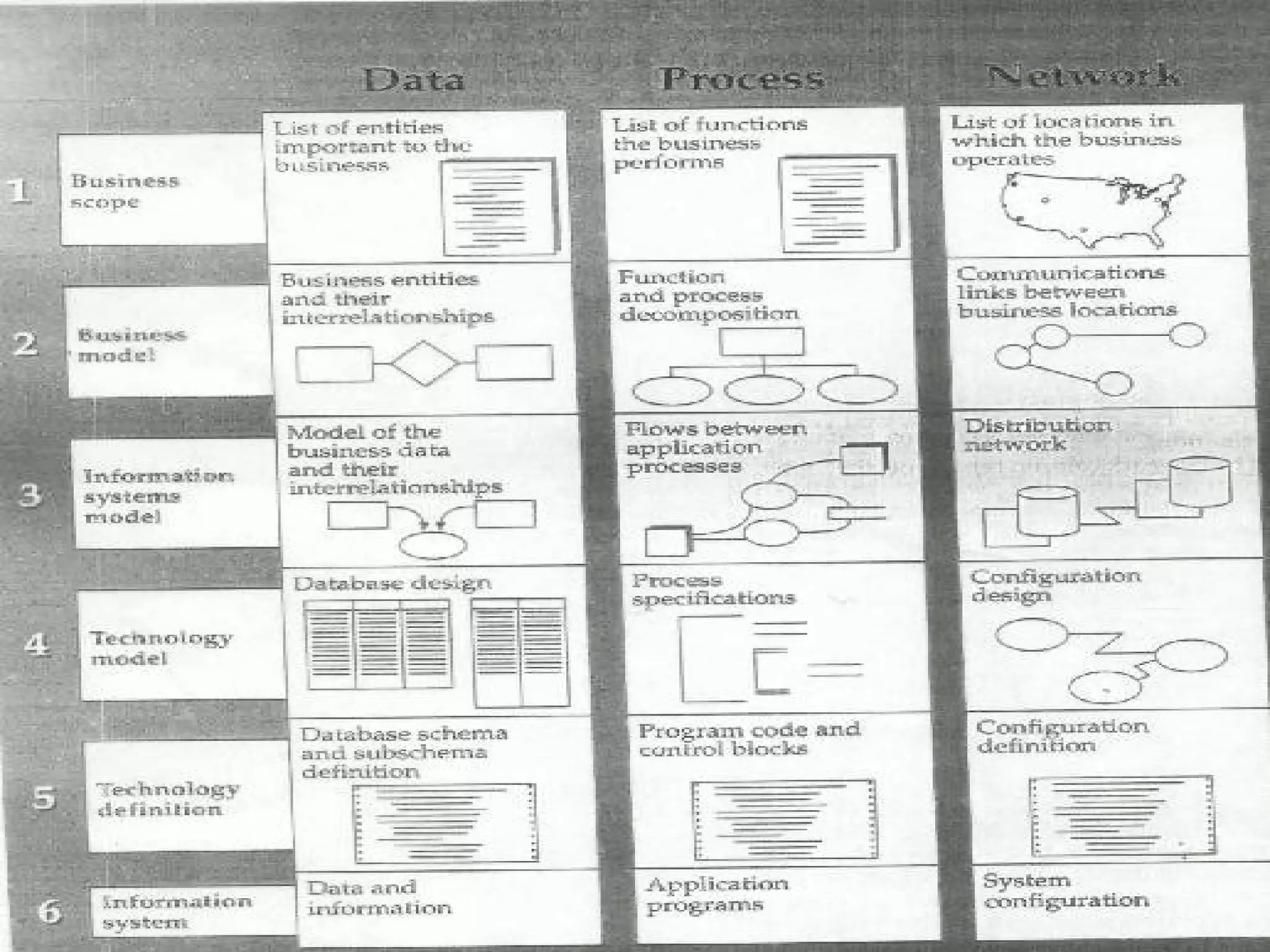
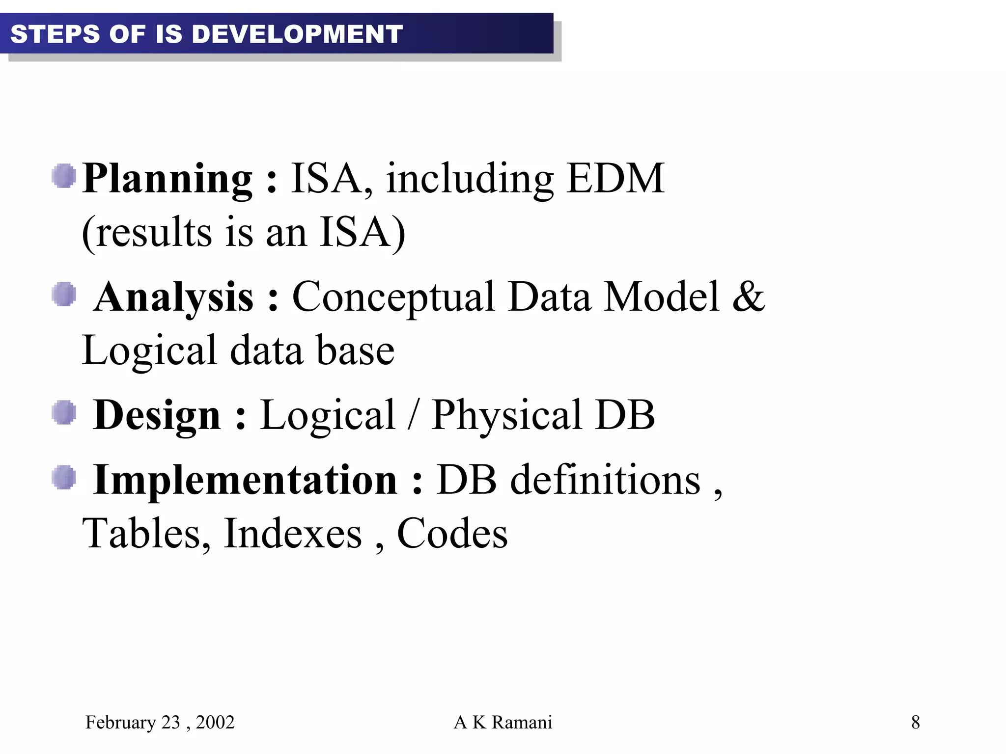
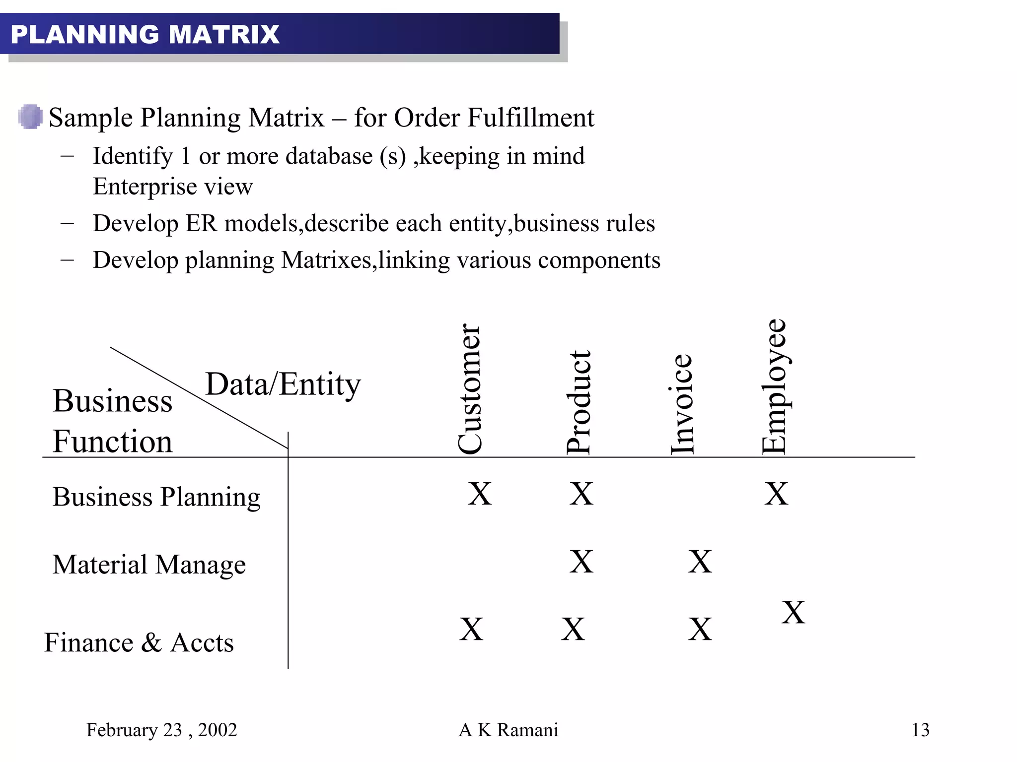
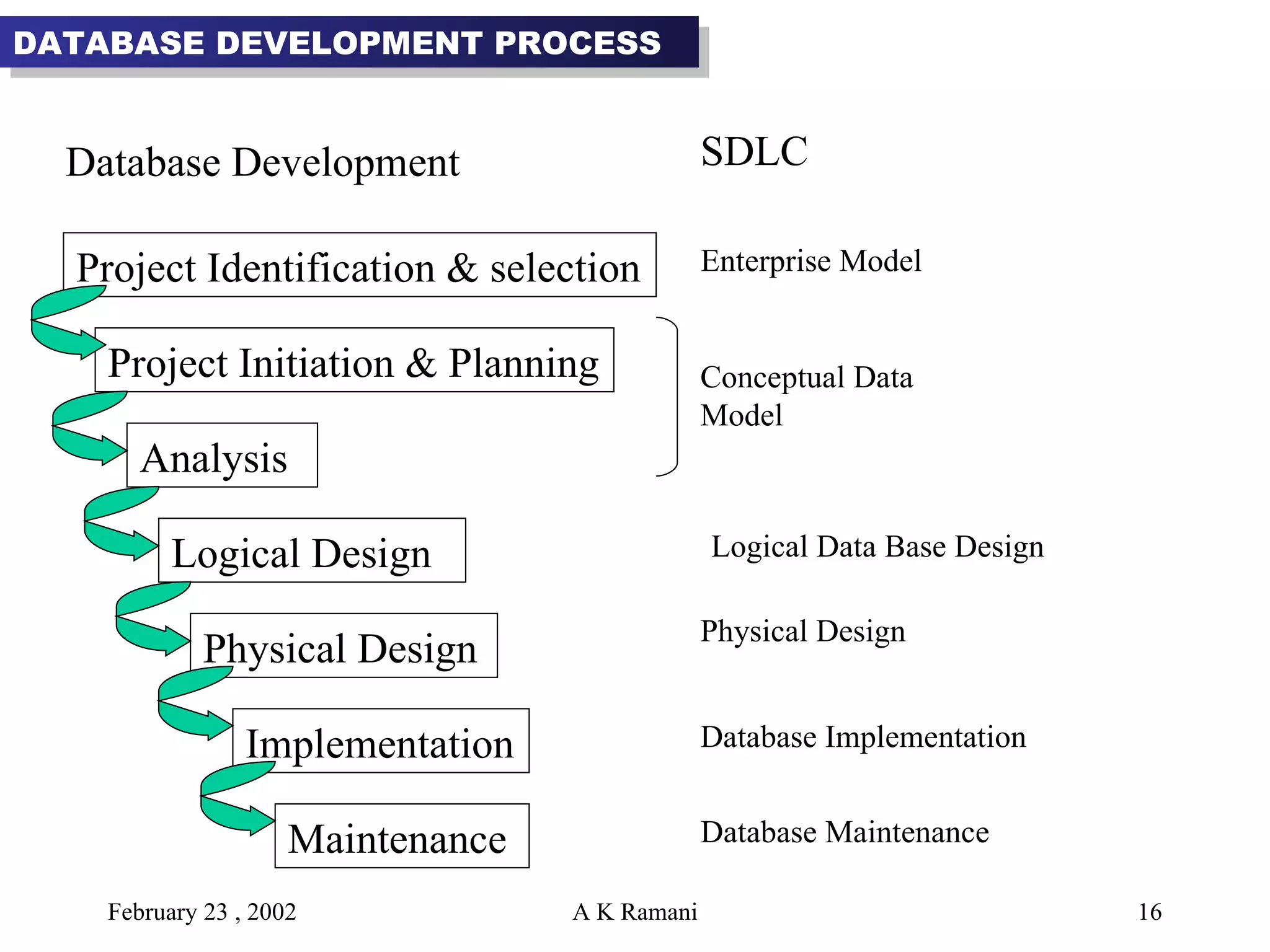
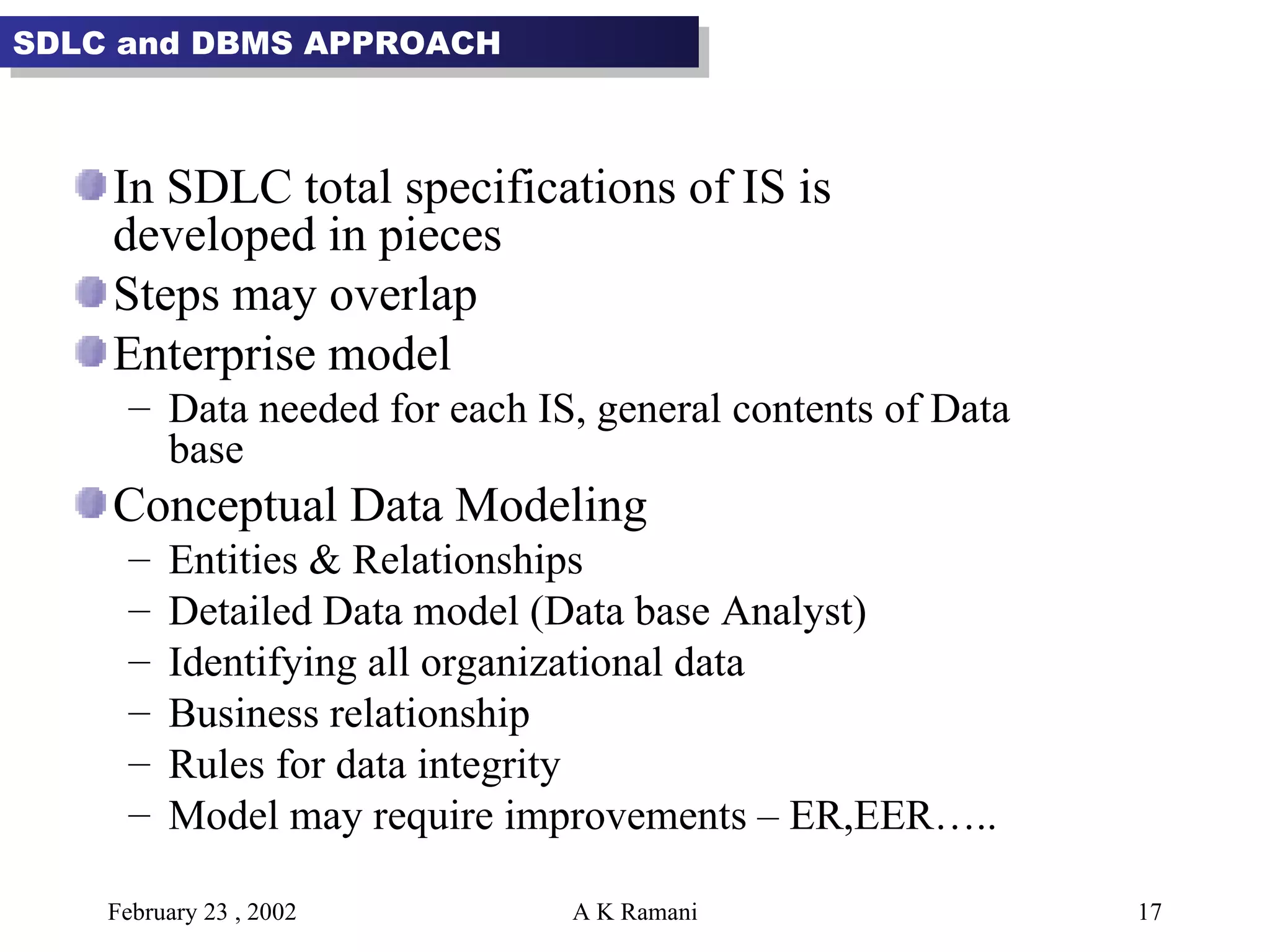
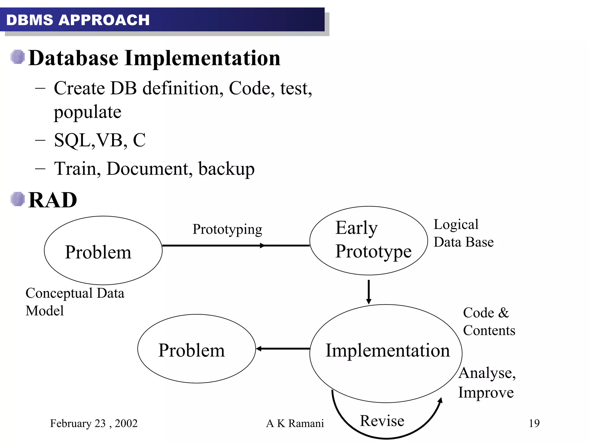
RECAP Role of Databases Classification  Evolution of Databases
Aim General steps in Design & Development of Databases in context to information system Development process. Objectives Understand Information System Architecture Database Analysis, Design and Implementation issues Design Example   DATABASE DEVELOPMENT PROCESS
Database development  Starts  with Enterprise Data Modeling (EDM) Steps in EDM Review current system Analyse the business area to be supported Data requirement Plan DB Project (s) EDM considers general contents of organizational  databases. Overall picture However, comprehensive architectural plan of IS  development is essential Features ISA can grow & expand (vision) Impact of Technology Flexible Eye on standards ENTERPRISE DATA MODELING
Planning Budget Overall direction of IT & decision Priority areas BENEFITS OF ISA
Data Process (DFD, Models) Network People Events & points in time (RTDB) Reason for Events , Rules KEY COMPONENTS OF ISA
 
A Data oriented methodology for development of information systems. For engineering IS, approach the Top-down methodology is followed where integration of individual system components takes place IS DEVELOPMENT
Planning :  ISA, including EDM (results is an ISA) Analysis :  Conceptual Data Model & Logical data base  Design :  Logical / Physical DB Implementation :  DB definitions , Tables, Indexes , Codes STEPS OF IS DEVELOPMENT
Goal :  To support Business Strategies with  IT  3 Steps Identify strategic planning factors – to develop planning context and to link information systems plan to the strategic plan of the organization Goals : Growth Rate, Return on Investment ( ROI )…….. Success Factors : Quality, On-time, Employee productivity….. Problem Areas : Competition, Maintenance of records…. IS PLANNING
2. Identify Corporate Planning objects – define the business scope Organizational Units – Various departments Locations – business places Business Functions – business processes like product development  4.  Entity Types : Categories of data about people, places &    things managed by company 5.  Information System : Application S/W & supporting    procedures.  IS PLANNING
3. Develop Enterprise Model – consists of a functional breakdown , an enterprise data model and various planning matrices. 1. Functional Decomposition – breaking down description of      system into finer and finer details, identify important      components. 2. High level ER diagram 3. Planning Matrices – A format for showing interrelationships    between data entities. Functions Support Functions Production Operation Scheduling, Fabrication,  Assembly Material Management Material requirement planning  - Purchasing - Receiving Marketing - Market research - Order fulfillment - Distribution IS PLANNING
Develop Enterprise Model Decompose business function Planning Matrixes (using ER) Functional decomposition helps in simplify problems , identify important components. Functions Support Functions Production Operation Scheduling, Fabrication,  Assembly Material Management Material requirement planning  - Purchasing - Receiving Marketing - Market research - Order fulfillment - Distribution
Sample Planning Matrix – for Order Fulfillment Identify 1 or more database (s) ,keeping in mind Enterprise view Develop ER models,describe each entity,business rules Develop planning Matrixes,linking various components  X PLANNING MATRIX Business Function Business Planning Material Manage Finance & Accts Customer Product Invoice Employee Data/Entity X X X X X X X X
Advantages  Identify Orphans : indicate which data entities are not used by any function or which functions do not use any entities Spot Missing Entities  Prioritize Development  PLANNING MATRIX
Types of Planning Matrices  Location to Function : which business functions are performed at which business locations Unit to Function : which business functions are performed at which business units Information System to Data Entity : explains how each information system interacts with data entity  Supporting Function to Data Entity : Identified which data are captured , used , updated or deleted within each function  Information System to Objective : Shows which information system support which business objective PLANNING MATRIX
Project Identification & selection Project Initiation & Planning Analysis Logical Design Physical Design Implementation Maintenance Enterprise Model Conceptual Data Model DATABASE DEVELOPMENT PROCESS Logical Data Base Design Physical Design Database Implementation Database Maintenance Database Development  SDLC
In SDLC total specifications of IS is developed in pieces Steps may overlap Enterprise model Data needed for each IS, general contents of Data base  Conceptual Data Modeling Entities & Relationships Detailed Data model (Data base Analyst) Identifying all organizational data Business relationship Rules for data integrity Model may require improvements – ER,EER….. SDLC and DBMS APPROACH
Logical Database Design Transform conceptual model Relations that are specific to DBMS used Transactions,  reports,displays to be supported What data are to be maintained in DB? Several users views to be integrated  Normalization : Process of designing well structured relations, avoid unnecessary duplication of data. Physical DB Design Identify programs to process transactions, generate reports Efficiency , Security H/W, OS, Network  SDLC and DBMS APPROACH
Database Implementation Create DB definition, Code, test, populate SQL,VB, C Train, Document, backup RAD Problem Early Prototype Implementation Problem Conceptual Data Model Prototyping Logical Data Base Code & Contents Analyse, Improve Revise DBMS APPROACH
Automated support to assist system Development process Draw data models using entity relationship Generate code Database definition commands    DBMS Compose SQL commands An information repository, which contains information needed to generate diagram, forms, reports.  CASE TOOLS
System Analyst  Analyze Business Data base Analyst  Data base Component User  Needs Programmer  Coding Database Administrator  Computer Architecture experts Construct GANTT/PERT Charts Review Points Senior DB/System Analyst is  LEADER PROJECT DEVELOPMENT
Users View Conceptual Schema Physical or Internal Schema ANSI Architecture User-1 User-2 User-n - - - Conceptual Scheme Internal Scheme Physical DB External Level Conceptual Level Internal Level MODEL / VIEW OF DATABASES
Data Independence is achieved by Inter-level Mapping Queries are translated between levels automatically Conceptual schema is encapsulated (independent of Database Management Technology) Physical schema is also encapsulated (specs to allocate & manage secondary memory) Develop Conceptual Schema Develop User View Physical Schema CA Features Performance Enterprise Data Model User Needs MODEL / VIEW OF DATABASES
Centralized DB System   Database DBMS DATABASES ARCHITECTURES
Distributed DB System DATABASES ARCHITECTURES Data Manager Transaction Manager DB
Client Server DB Client : User System Interface & localized Data Sever : Shared Data CLIENT CLIENT SERVER DB DBMS DATABASES ARCHITECTURES
Client Server (2 Tired) Thin Client / Fat Server Fat Client / Thin Server DB Server Server DATABASES ARCHITECTURES
Client Server (3 Tiered) DB Server Client (s) DATABASE Dept. Server (Application Server) Organizational Server (Higher Level) Merging or Data DATABASES ARCHITECTURES
DB –Driven Web Applications Advantages Multi –processing Advantages of each computer platform (PCs, Servers) Mix Client Technologies (Thin Client) Processing close to data , reduces traffic Open System Standards DB Server WEB+Application Server Internet DATABASES ARCHITECTURES
Summary General steps in DB development ISA, EDM DB Architectures

Database 2 External Schema

  • 1.
    RECAP Role ofDatabases Classification Evolution of Databases
  • 2.
    Aim General stepsin Design & Development of Databases in context to information system Development process. Objectives Understand Information System Architecture Database Analysis, Design and Implementation issues Design Example DATABASE DEVELOPMENT PROCESS
  • 3.
    Database development Starts with Enterprise Data Modeling (EDM) Steps in EDM Review current system Analyse the business area to be supported Data requirement Plan DB Project (s) EDM considers general contents of organizational databases. Overall picture However, comprehensive architectural plan of IS development is essential Features ISA can grow & expand (vision) Impact of Technology Flexible Eye on standards ENTERPRISE DATA MODELING
  • 4.
    Planning Budget Overalldirection of IT & decision Priority areas BENEFITS OF ISA
  • 5.
    Data Process (DFD,Models) Network People Events & points in time (RTDB) Reason for Events , Rules KEY COMPONENTS OF ISA
  • 6.
  • 7.
    A Data orientedmethodology for development of information systems. For engineering IS, approach the Top-down methodology is followed where integration of individual system components takes place IS DEVELOPMENT
  • 8.
    Planning : ISA, including EDM (results is an ISA) Analysis : Conceptual Data Model & Logical data base Design : Logical / Physical DB Implementation : DB definitions , Tables, Indexes , Codes STEPS OF IS DEVELOPMENT
  • 9.
    Goal : To support Business Strategies with IT 3 Steps Identify strategic planning factors – to develop planning context and to link information systems plan to the strategic plan of the organization Goals : Growth Rate, Return on Investment ( ROI )…….. Success Factors : Quality, On-time, Employee productivity….. Problem Areas : Competition, Maintenance of records…. IS PLANNING
  • 10.
    2. Identify CorporatePlanning objects – define the business scope Organizational Units – Various departments Locations – business places Business Functions – business processes like product development 4. Entity Types : Categories of data about people, places & things managed by company 5. Information System : Application S/W & supporting procedures. IS PLANNING
  • 11.
    3. Develop EnterpriseModel – consists of a functional breakdown , an enterprise data model and various planning matrices. 1. Functional Decomposition – breaking down description of system into finer and finer details, identify important components. 2. High level ER diagram 3. Planning Matrices – A format for showing interrelationships between data entities. Functions Support Functions Production Operation Scheduling, Fabrication, Assembly Material Management Material requirement planning - Purchasing - Receiving Marketing - Market research - Order fulfillment - Distribution IS PLANNING
  • 12.
    Develop Enterprise ModelDecompose business function Planning Matrixes (using ER) Functional decomposition helps in simplify problems , identify important components. Functions Support Functions Production Operation Scheduling, Fabrication, Assembly Material Management Material requirement planning - Purchasing - Receiving Marketing - Market research - Order fulfillment - Distribution
  • 13.
    Sample Planning Matrix– for Order Fulfillment Identify 1 or more database (s) ,keeping in mind Enterprise view Develop ER models,describe each entity,business rules Develop planning Matrixes,linking various components X PLANNING MATRIX Business Function Business Planning Material Manage Finance & Accts Customer Product Invoice Employee Data/Entity X X X X X X X X
  • 14.
    Advantages IdentifyOrphans : indicate which data entities are not used by any function or which functions do not use any entities Spot Missing Entities Prioritize Development PLANNING MATRIX
  • 15.
    Types of PlanningMatrices Location to Function : which business functions are performed at which business locations Unit to Function : which business functions are performed at which business units Information System to Data Entity : explains how each information system interacts with data entity Supporting Function to Data Entity : Identified which data are captured , used , updated or deleted within each function Information System to Objective : Shows which information system support which business objective PLANNING MATRIX
  • 16.
    Project Identification &selection Project Initiation & Planning Analysis Logical Design Physical Design Implementation Maintenance Enterprise Model Conceptual Data Model DATABASE DEVELOPMENT PROCESS Logical Data Base Design Physical Design Database Implementation Database Maintenance Database Development SDLC
  • 17.
    In SDLC totalspecifications of IS is developed in pieces Steps may overlap Enterprise model Data needed for each IS, general contents of Data base Conceptual Data Modeling Entities & Relationships Detailed Data model (Data base Analyst) Identifying all organizational data Business relationship Rules for data integrity Model may require improvements – ER,EER….. SDLC and DBMS APPROACH
  • 18.
    Logical Database DesignTransform conceptual model Relations that are specific to DBMS used Transactions, reports,displays to be supported What data are to be maintained in DB? Several users views to be integrated Normalization : Process of designing well structured relations, avoid unnecessary duplication of data. Physical DB Design Identify programs to process transactions, generate reports Efficiency , Security H/W, OS, Network SDLC and DBMS APPROACH
  • 19.
    Database Implementation CreateDB definition, Code, test, populate SQL,VB, C Train, Document, backup RAD Problem Early Prototype Implementation Problem Conceptual Data Model Prototyping Logical Data Base Code & Contents Analyse, Improve Revise DBMS APPROACH
  • 20.
    Automated support toassist system Development process Draw data models using entity relationship Generate code Database definition commands  DBMS Compose SQL commands An information repository, which contains information needed to generate diagram, forms, reports. CASE TOOLS
  • 21.
    System Analyst Analyze Business Data base Analyst Data base Component User Needs Programmer Coding Database Administrator Computer Architecture experts Construct GANTT/PERT Charts Review Points Senior DB/System Analyst is LEADER PROJECT DEVELOPMENT
  • 22.
    Users View ConceptualSchema Physical or Internal Schema ANSI Architecture User-1 User-2 User-n - - - Conceptual Scheme Internal Scheme Physical DB External Level Conceptual Level Internal Level MODEL / VIEW OF DATABASES
  • 23.
    Data Independence isachieved by Inter-level Mapping Queries are translated between levels automatically Conceptual schema is encapsulated (independent of Database Management Technology) Physical schema is also encapsulated (specs to allocate & manage secondary memory) Develop Conceptual Schema Develop User View Physical Schema CA Features Performance Enterprise Data Model User Needs MODEL / VIEW OF DATABASES
  • 24.
    Centralized DB System Database DBMS DATABASES ARCHITECTURES
  • 25.
    Distributed DB SystemDATABASES ARCHITECTURES Data Manager Transaction Manager DB
  • 26.
    Client Server DBClient : User System Interface & localized Data Sever : Shared Data CLIENT CLIENT SERVER DB DBMS DATABASES ARCHITECTURES
  • 27.
    Client Server (2Tired) Thin Client / Fat Server Fat Client / Thin Server DB Server Server DATABASES ARCHITECTURES
  • 28.
    Client Server (3Tiered) DB Server Client (s) DATABASE Dept. Server (Application Server) Organizational Server (Higher Level) Merging or Data DATABASES ARCHITECTURES
  • 29.
    DB –Driven WebApplications Advantages Multi –processing Advantages of each computer platform (PCs, Servers) Mix Client Technologies (Thin Client) Processing close to data , reduces traffic Open System Standards DB Server WEB+Application Server Internet DATABASES ARCHITECTURES
  • 30.
    Summary General stepsin DB development ISA, EDM DB Architectures