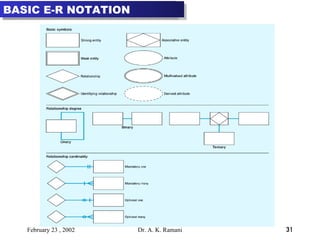
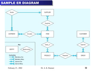
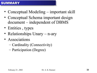
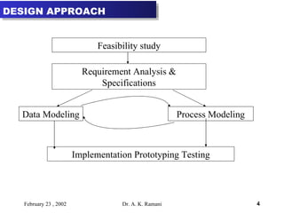
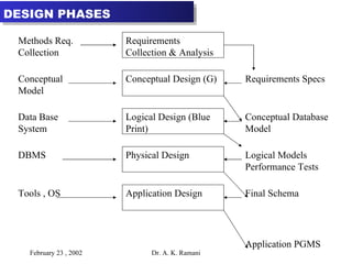
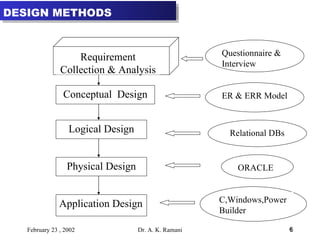
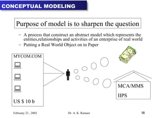
The document discusses conceptual data modeling and entity-relationship (ER) modeling. It describes the key concepts in ER modeling including entities, attributes, relationships, cardinality, participation, and relationship types. It provides examples of how to model different types of relationships, attributes, and entities. The goal of conceptual modeling is to build an abstract yet rigorous model of an organization's data to help communicate requirements and ensure quality.


![A model is a means of communication Users of a model must have a certain amount of knowledge in common A model on emphasized selected aspects A model is described in some language A model can be erroneous A message to map makers: “Highways are not painted red, rivers don’t have county lines running down the middle, and you can’t see contour lines on a mountain” [Kent 78] MODEL TO RAISE QUESTION](https://image.slidesharecdn.com/database3-conceptualmodelingander-090916074121-phpapp01/85/Database-3-Conceptual-Modeling-And-Er-9-320.jpg)
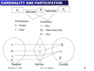
![How is an entity linked to relationship ? [Participation] How many relationship instances is an entity permitted to be linked to ? [cardinality] Relationship instance is an association between entity instances, where each instance includes exactly one entity from each participating entity type JUSTIFICATION Student Advise Faculty Akr Trupti Kris Ram Mohan Singh](https://image.slidesharecdn.com/database3-conceptualmodelingander-090916074121-phpapp01/85/Database-3-Conceptual-Modeling-And-Er-20-320.jpg)