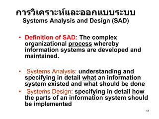
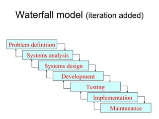
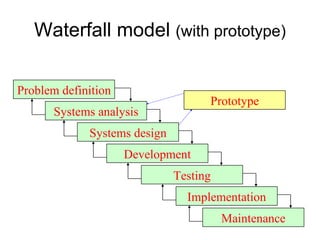
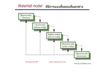
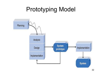
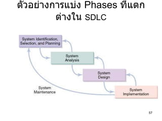
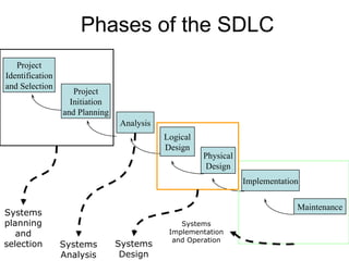
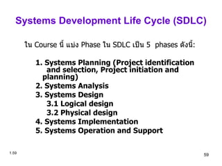
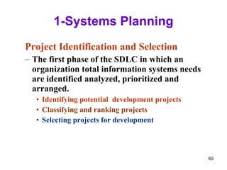
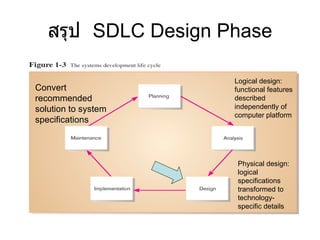
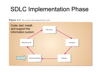
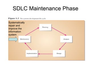
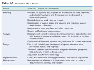
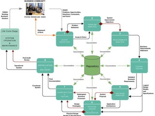
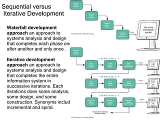
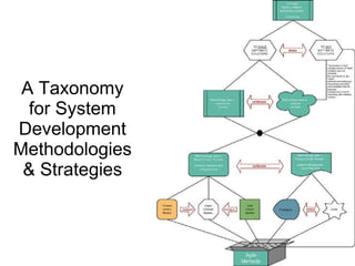
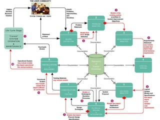
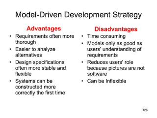
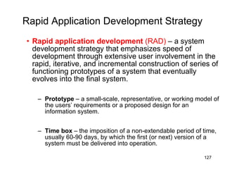
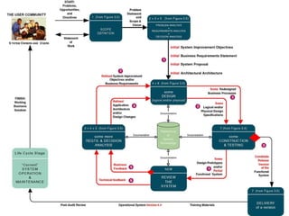
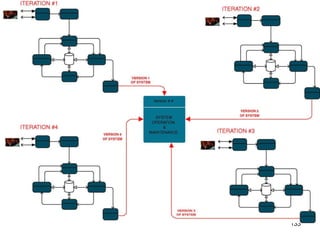
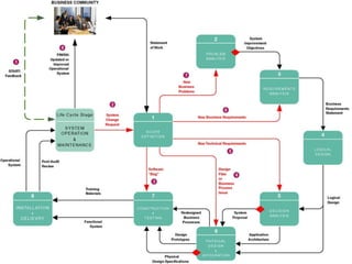
บทที่  3 SAD, SDLC  System development process
หัวข้อการบรรยาย เนื้อหาที่จะเรียนในครั้งนี้  : SAD:   การวิเคราะห์และออกแบบระบบงาน แนวคิดและความหมายและ ของการวิเคราะห์และออกแบบระบบงาน องค์ประกอบของระบบงานสารสนเทศ SDLC  :The  S ystem  D evelopment  L ife  C ycle
เทคโนโลยีสารสนเทศ Information  Technology ( IT ) “ เทคโนโลยีที่ประกอบขึ้นด้วย  ระบบจัดเก็บ  และ  ประมวลผลข้อมูล   ระบบสื่อสารโทรคมนาคม   และ  อุปกรณ์สนับสนุนการ   ปฎิบัติงานด้านสารสนเทศ   ที่มีการวางแผน  จัดการ  และใช้งานร่วมกันอย่างมีประสิทธิภาพ   “
Information System ระบบที่ประกอบด้วย  ข้อมูล  ( data)   วิธีการ ประมวลผล  (process)   และ กลุ่มคน   (people)   ที่ทำหน้าที่ประมวลผลข้อมูล  เพื่อให้ได้สารสนเทศที่ใช้สนับสนุนการทำงานขององค์กรในระดับปฏิบัติการ  รวมทั้งสนับสนุนการทำงานในระดับบริหาร  อาทิ  การวางแผนงาน  การตัดสินใจ  การกำหนดกลยุทธ์ ฯลฯ
Information System Development Information Systems Data Process Programs Manual Procedure Database System Data Oriented Process Oriented
ระบบฐานข้อมูล Database DBMS OS OS : Operating System DBMS = DATABASE MANAGEMENT SYSTEM DATABASE SYSTEM =  DATABASE + DBMS
Application Systems  Database DBMS OS Application Software Development Tools  vs Programming Language
Client/Server Application Runtime Database Server
Three-tier Architecture Web browser Application Server Database Server
Views of Systems Development How to build information systems How to analysis information system needs How to design computer based information systems How to solve systems problems in organizations
การวิเคราะห์และออกแบบระบบ Systems Analysis and Design (SAD) Definition of SAD:   The complex  organizational  process  whereby information systems are developed and maintained.   Systems Analysis:  understanding and specifying in detail  what  an information system existed and what should be done Systems Design:  specifying in detail  how  the parts of an information system should be implemented
Why is it important? Success of information systems depends on good SAD
Critical Questions What  should we develop? When  should we develop? Who  will be responsible for the development? How  should we proceed? Based on org.  goals & strategic  direction
Systems and the Real World Systems Analyst A real-world situation or problem Thinks about Makes comparisons A system that helps to understand the real-world situation Designs INPUT OUTPUT PROCESS FEEDBACK A computer system that  is used in the real-world
Thinking like an Analyst The Helicopter Perspective The “Helicopter Perspective” is a simple approach to abstraction:  Start from high up... Get the big picture. Go a bit lower … Examine the next level of detail.   One trick to thinking like an analyst is to imagine looking at your problem from a helicopter
Levels of Abstraction The Helicopter Perspective encourages analysts to view a problem domain or system at various levels of abstraction - seeing the Forest NOT the Trees.  Once you have the big picture you can then zoom in to examine the detail.
There are many ways of developing an information system พัฒนาระบบงานขึ้นใช้โดยหน่วยงานสารสนเทศภายในองค์กรเอง จ้างบุคลากรภายนอกทำการพัฒนาระบบให้  (Outsourcing) ซึ่งอาจจะเป็นการพัฒนาทั้งระบบหรือบางส่วนของระบบ ซื้อโปรแกรมสำเร็จรูปมาใช้ A variety of development aids exist including methodologies( models, tools, and techniques)
Systems Development Methodologies ระเบียบวิธีการพัฒนาระบบ - A sequence of step-by-step approaches that help develop the information system. It is a formalized approach to implement SDLC. (including specific models, tools, techniques and  a list of steps and deliverables) Methodology  ( ระเบียบวิธี ) ลำดับขั้นของกิจกรรมที่มีการวางแผนและกำหนดความสำคัญก่อนหลังรวมทั้งเทคนิคและเครื่องมือต่างๆ ที่จะทำให้กิจกรรมแต่ละข ั้ นสำเร็จต่อเนื่องกัน จนบรรลุเป้าหมายตามที่ได้กำหนดไว้
Model A representation of some important  aspect of the real world. การใช้แผนภาพ หรือ รูปแบบการเขียน ที่ กำหนดไว้   เพื่ออธิบายถึง กิจกรรม หรือ  องค์ประกอบ ในระบบสารสนเทศ Model   จะช่วยให้เกิดความเข้าใจได้ง่ายขึ้น
Tools Software support that helps create  models or other components required  in the project.
Technique  A collection of guidelines that help the  analyst complete a system development activity or task.
Relationships Among Components  of a Methodology
Some  models   of system components Flow chart Data flow diagram (DFD) Entity relationship diagram (ERD) Structure chart Use case diagram Class diagram Sequence diagram
Some  models  used to manage  the development process PERT chart Gantt chart Organizational hierarchy chart Financial analysis models – NPV, ROI
Process Models A  process model  is a model abstracting the process of system development. By establishing a process model, the procedures of system development are given a direction or a guideline. The table below shows various models and their characteristics.
Some  models  used to develop system Waterfall model Prototyping Model Spiral Model Phased Model — Increments & Iterations
Waterfall model  (iteration added) Systems design Testing Problem definition Systems analysis Development Implementation Maintenance
Waterfall model  (with prototype) Systems design Prototype Problem definition Systems analysis Development Implementation Maintenance Testing
ที่มีการแบ่งขั้นตอนที่แตกต่าง
pros กระบวนการพัฒนาระบบสามารถกำหนดเป็นโครงสร้างที่แน่นอนมีขั้นตอนที่ชัดเจนและติดตามการทำงานในแต่ละขั้นตอนได้ง่าย ผู้บริหาร / เจ้าของโครงการรับทราบในทุกขั้นตอนเนื่องจาก นักวิเคราะห์ระบบต้องนำเสนอเพื่อขอความเห็นชอบจากผู้บริหาร / เจ้าของโครงการ ในแต่ละขั้นตอนจึงจะดำเนินการในขั้นตอนต่อไปได้ Waterfall Model  — PROS AND CONS
Waterfall Model  — PROS AND CONS cons การพัฒนาต้องเป็น  step  ไปตามแต่ละขั้นตอนเป็นแบบ   linear development –>  ซึ่งขั้นตอนที่สองจะทำได้ต่อเมื่อขั้นตอนที่หนึ่งเสร็จสิ้นลง เป็นแบบ  sequential flow of activities–> การเปลี่ยนแปลงแก้ไฃปรับปรุงความต้องการทำได้ยาก ผลลัพธ์ที่ได้ในแต่ละขั้นตอนจะถูก  frozen   ก่อนที่จะทำขั้นตอนต่อไป ถ้างานที่กำลังทำอยู่ในขั้นตอนหนึ่งๆยังไม่ชัดเจนพอที่จะทำขั้นตอนต่อไปได้ก็จะต้องทำขั้นตอนนั้นให้สำเร็จเรียบร้อยก่อน ระยะเวลาที่ใช้ในขั้นตอนการวิเคราะห์และออกแบบระบบงานค่อนข้างนานและต้องจัดทำเป็นเอกสารก่อนจะเริ่มพัฒนาระบบจริง – >  ทำให้ไม่ทราบ  feedback  จนกว่าการพัฒนาแล้วเสร็จ ความผิดพลาดมักตรวจสอบพบหลังจากการพัฒนาสิ้นสุดแล้วซึ่งเสียทั้งค่าใช้จ่ายและเวลา หรือในบางกรณีนานจนความต้องการหรือสถานการณ์เปลี่ยนไปแล้ว
Prototyping Model
Prototyping An  iterative process  of systems development in which  requirements  are converted to a  working system  that is continually revised through close work between an analyst and users. You can build prototype by  some development tool to simplify the process. CASE: Computer Aided Software Tools such as Oracle (designer 2000) 4GLs: fourth-generation languages
Waterfall & Prototyping
PROTOTYPING — PROS AND CONS pros สำรวจและทราบความต้องการได้อย่างรวดเร็ว  สามารถนำความคิดเห็นของผู้ใช้มาปรับแต่งระบบได้ทันท่วงที ลดความเสี่ยงที่จะเกิดจากระบบไม่ตรงความต้องการของผู้ใช้ cons ไม่ใช่วิธีการพัฒนาระบบที่สมบูรณ์อย่างแท้จริง  – >  ส่วนมากจะใช้ร่วมกับวิธีการแบบอื่น “ product”  ที่ได้ไม่ใช่ระบบงานจริงที่สมบูรณ์แบบแต่มักถูกใช้เป็นระบบงานจริง มักจะไม่มีเอกสารประกอบระบบงาน
 
SPIRAL Model —  PROS AND CONS Pros รวมลักษณะที่ดีของ  waterfall model  กับ   prototyping  กล่าวคือ สามารถดัดแปลงระบบได้ตลอดเวลาการพัฒนาระบบ มีกลไกการลดความเสี่ยงโดยใช้การพัฒนาแบบต้นแบบในขั้นตอนใดก็ได้ทำให้เห็นความเสี่ยงทางเทคนิคกับทุกขั้นตอนของงาน การพัฒนาแต่ละวงรอบทำให้เห็นปัยหาต่างๆที่เกิดขึ้นในแต่ละรอบ cons ต้องการผู้เชี่ยวชาญในเรื่องการวิเคราะห์ความเสี่ยง
Spiral model: It is a process model in which the methods of both the  waterfall model and the prototyping model are incorporated.  If a large-volume application can be divided into mutually highly  independent components, for each component, either the waterfall  model or the prototyping model is applied. •  Development staff can be secured in a stable manner. •  Scales of simultaneous development can be controlled. Subsystems are developed independently. Spiral model  •  Final stages will have few corrections and reviews. •  The requirements are clarified in early stages. A prototype of the user interface is developed to  clarify the requirements. Prototyping model •  There are always activities that require iteration. •  It is difficult to clarify all of the requirements in  the initial stages of the development. •  Each phase is reviewed at the time of its completion  for quality management. Each phase of the development process flows from  upstream to downstream, without going back. Waterfall model Characteristics Name
PHASED Model — INCREMENTS & ITERATIONS การพัฒนาระบบแบบเพิ่มพูน – > partial system; full functionality การพัฒนาระบบแบบทำซ้ำ – > full system; partial functionality
PHASED Model Build release 1 Build release 2 Build release 3 Use release 1 Use release 2 Use release 3 Time Developers Users
Pros เริ่มต้นการฝึกอบรม และทราบ  feedback  ได้รวดเร็ว  ตั้งแต่การทดลองใช้  release  แรกๆ เป็นการพัฒนาเพื่อให้ทราบความต้องการของผู้ใช้ในเบื้องต้น และปรับเพิ่มความต้องการใน  release  ต่อๆไป สามารถ แก้ไข  bugs  เมื่อออก  release  ใหม่ development team can focus on different areas of expertise with each release Cons ใน  release  แรกๆการใช้งานอาจจะยังไม่สมบรณ์ PHASED model — PROS and CONS
Cost Models Software cost is the cost incurred in each process of the lifecycle of software development (Software Development Life Cycle: SDLC). A  cost model  is a model to quantify the cost (i.e., productivity) such as the productivity and quality measures of the software. Cost models and characteristics are shown in the following table.
Cost Models The numbers of the five elements—input, output, inquiry, logical files, and interfaces—are obtained and added up with weights. Based on the assumption that this weighted sum is in correlation with the scale of the software development, the development size is estimated. The view held by this method is that what the users really need is not the programs but the functions.  FP  (Function Point) method The programmer's work load is calculated in terms of cost based on a mathematical formula, using a statistical model, consisting of basic, intermediate, and advanced (detailed) levels. COCOMO model  Characteristics Name
Some  tools  used in  system development Project management application Drawing/graphics application Word processor/text editor Computer-aided system engineering (CASE) tools Integrated development environment (IDE) Database management application Code generator tools
Some  techniques  used in system development Strategic planning techniques Project management techniques User interviewing techniques Data modeling techniques Relational database design techniques
Some  techniques  used in system development Structured analysis techniques Structured design techniques Structured programming techniques Software testing techniques Object oriented analysis and design techniques
Systems Development Methodologies 1. Structured System Analysis and Design  Methodology (SSADM) 2. Rapid Application Development-based Methodology (RAD) 3. Objected-Oriented Analysis and Design Methodology (OOAD)
Systems Development Methodologies  Structured System Analysis and Design  Methodology (SSADM) -  เป็นวิธีการที่ใช้ในการพัฒนาระบบที่เป็นขั้นตอนในรูปแบบ  Waterfall  เริ่มใช้ปี ค . ศ .  1980 -  ใช้แผนภาพจำลองขั้นตอนการทำงานของระบบ  -  Process center approach -  เมื่อเสร็จสิ้นการทำงานในแต่ละขั้นตอนต้องนำเสนอผู้บริหาร / เจ้าของระบบเพื่อพิจารณาอนุมัติก่อนดำเนินการใน ขั้นตอนถัดไป
Systems Development Methodologies  Rapid Application Development-based Methodology ( RAD ) -  ถูกพัฒนาขึ้นใช้ในปี ค . ศ . 1990  เพื่อแก้ไขจุดอ่อนของ  SSADM  โดยมีขั้นตอนในการพัฒนาระบบที่รวบรัดมากขึ้นลดระยะเวลาที่ใช้ในการออกแบบและ  implement  ระบบ และใช้  tools  และ  techniques  ที่ช่วยให้การพัฒนาระบบ  ทำได้อย่างรวดเร็วขึ้น เช่น  CASE tools, prototyping  ทำให้ผู้ใช้เข้าใจระบบได้ดีขึ้นและสามารถเสนอแนะข้อปรับปรุงต่างๆให้การพัฒนาระบบออกมาตรงกับสิ่งที่ต้องการ
Rapid Application Development ( RAD ) Involves:  prototyping, JAD, CASE tools, and code generators
Joint Application Design (JAD) JAD  พัฒนาขึ้นช่วงปลายปี  1970  โดยบุคลากรของบริษัท  IBM  เพื่อใช้ในการเก็บรวบรวมข้อมูลความต้องการของผู้ใช้และทบทวนการออกแบบของระบบ (   a new process for collecting IS requirements and reviewing system design.)  Definition : It is structured process in which users, managers, and analysts work together for several days in a series of intensive meeting to specify or review system requirements
Joint Application Design ( JAD ) Structured process involving users, analysts, and managers Several-day intensive workgroup sessions Purpose: to specify or review system requirements
A  more recent approach to system development that is becoming is object oriented analysis and design (OOAD). It is often called  third  approach to system development, after the  process oriented  and  data oriented  approaches Definition: OOAD The systems development methodologies and techniques base on  objects  rather than  data  or  process  Systems Development Methodologies O bject  O riented  A nalysis and  D esign ( O O A D )
Grady Booch, Ivar Jacobson and James Rumbaugh  ร่วมกันพัฒนามาตรฐานแผนภาพที่ใช้ในการวิเคราะห์และออกแบบระบบงานเชิงวัตถุ  - UML (Unified Modeling Language) Systems Development Methodologies O bject  O riented  A nalysis and  D esign ( O O A D )
S ystem  D evelopment  L ife  C ycle วงจร / วัฎจักรการพัฒนาระบบงาน เป็น   logical process  ของก ารพัฒนาระบบสารสนเทศเพื่อแก้ปัญหาที่มีอยู่ในการใช้งานระบบปัจจุบันและตอบสนองความต้องการของผู้ใช้ระบบงานนั้นๆ   โดยมีการแบ่งขั้นตอนการทำงานออกเป็น   phase  ต่างๆ   แตกต่างกันไป It is a common methodology for systems often follows for system development in many organization, featuring several  phases  that mark the progress of the systems analysis and design effort.
System development phases ขั้นตอนต่างๆในการพัฒนาระบบ A standard process followed in an organization to conduct all the steps necessary to: Plan Analyze Design Implement Maintain  information system
ตัวอย่างการแบ่ง  Phases   ที่แตกต่างใน   SDLC
Project Initiation and Planning Analysis Logical Design Physical Design Implementation Project Identification and Selection Maintenance Phases of the SDLC Systems Implementation and Operation Systems Design Systems Analysis Systems planning and selection
Systems Development Life Cycle (SDLC) ใน  Course  นี้ แบ่ง  Phase  ใน  SDLC  เป็น  5  phases  ดังนี้ : 1. Systems Planning (Project identification  and selection, Project initiation and  planning) 2. Systems Analysis 3. Systems Design 3.1 Logical design 3.2 Physical design 4. Systems Implementation 5. Systems Operation and Support 1 .
1-Systems Planning Project Identification and Selection The first phase of the SDLC in which an organization total information systems needs are identified analyzed, prioritized and arranged. Identifying potential  development projects Classifying and ranking projects Selecting projects for development
1- Systems Planning Project Initiating and Planning Study the feasibility of the selected projected.  This stage is critical to the success of the rest of the project. People: Users, analyst, management decide whether or not to continue the project. Activities : Interviewing user management, summarizing the knowledge obtained  estimating the scope of the project and documenting the result –  Define  the problem and determine whether or not the new system is feasible. Output: Feasibility report/Preliminary report: problem definition and summarizing the objectives
1- Systems Planning Diagrams, Tools and Techniques : Fact gathering techniques,  Cost-benefit Analysis,  Gantt chart, PERT
2-Systems Analysis  ขั้นตอนที่สองของ   SDLC  คือการศึกษาการทำงานของระบบปัจจุบันและนำเสนอทางเลือกในการปรับปรุงเปลี่ยนแปลงระบบ   Description of current system Where problem and opportunities are with a general recommendation on how to  fix, enhance or replace current system
2-Systems Analysis Analyzing systems needs วัตถุประสงค์หลักของขั้นตอนการวิเคราะห์ระบบคือการทำความเข้าใจการทำงานของระบบปัจจุบันและรวบรวมความต้องการของผู้ใช้และองค์กรและวิเคราะห์ความจำเป็นของขั้นตอน  อุปกรณ์ และอื่นๆที่นักวิเคราะห์ระบบเห็นว่าควรมีในระบบงานใหม่ .   กิจกรรมหลักที่ต้องทำในขั้นตอนนี้ได้แก่ : •   Gather information. •   Define system requirements. •   May build prototypes for discovery of  requirements . •   Prioritize requirements. •   Generate and evaluate alternatives. •   Review recommendations with management
2-Systems Analysis People: Users, analyst, management decide whether or not to continue the project. Activities : Study and document the current system in order to understand both its flows and its strong points.  Prepare a list of requirements for a new system. Output: Systems requirements documents describes management and user requirements, alternative plans and costs and SA recommendations
2-Systems Analysis Diagrams, Tools and Techniques : Fact gathering techniques Data Flow Diagram E-R Diagram Data Dictionary Prototyping CASE tools
3-Systems Design  วัตถุประสงค์หลักของการออกแบบระบบคือการเปลี่ยน  (convert)  ทางเลือก  (the description of the recommended alternative solution)  ที่ผู้ใช้เลือกในขั้นตอนการวิเคราะห์ระบบให้เป็น  system specification .  It is the third phase of the SDLC in which the description of the recommended solution is converted into  logical  and then  physical  system specification.
3-Systems Design  . Logical design: The part of the design phase of the SDLC in which all functional feature of the system chosen for development in analysis are described independently of any computer platform. High-level design consists of developing an architectural structure for software programs, databases, the user interface, and the operating environment.
3-Systems Design  Physical design: The part of the design phase of the SDLC in which the logical specification of the system from logical design are transformed into technology specific details from which all programming and system construction can be accomplished. Low-level design entails developing the detailed algorithms and data structures that are required for program development.
3-Systems Design 3.1 Logical design People: Analyst, users and management review the design specification for the completeness. Activities : Transform the functional diagram of the analysis to hierarchy diagram of design phase. Forms/reports design. User interface design Logical database design Output: System design specifications - Functional, Detailed specification of all system elements  Input , Output, Process
3-Systems Design 3.1 Logical design Diagrams, Tools and Techniques : Fact gathering techniques Data Flow Diagram E-R Diagram Data Dictionary Prototyping Hierarchy chart CASE Tools
3-Systems Design 3.2 Physical design People: Analyst designs physical databases and define systems architecture.  Activities : Design physical databases. Design Applications (define systems architecture. OS platform, order all necessary hardware and software). Output: System specification of all system elements programs, tables, network, system software etc . Acquisition plan of a new technology
3-Systems Design 3.2 Physical design Diagrams, Tools and Techniques : Process specification Program flowchart/Structure chart Table specifications Data Dictionary Prototyping Hierarchy charts CASE Tools
3-Systems Design   สรุปกิจกรรมที่ต้องทำในขั้นตอนการออกแบบ ได้แก่  (seven major activities must be done during design): Design and integrate the network. Design the application architecture. Design the user interfaces . Design the system interfaces. Design and integrate the databases. Prototype for design details.  Design and integrate the system controls
4- Systems Implementation The fourth phase of the SDLC in which the information system is  Coded,  Tested,  Installed, and  Supported in the organization.
4- Systems Implementation People: Users, analyst, management decide whether or not to continue the project. Activities : Coding and testing programs. Installation Documentation and training Output: Code, documentation, training procedures and support capabilities
4- Systems Implementation Diagrams, Tools and Techniques : Various program ‘s tools Structure walkthrough Testing and Documentation procedures CAI, CBT, WBT
Software Conversion Strategies
5-Systems Operation and Support The final phase of the SDLC in which the information system is systematically repaired and improved
5-Systems Operation and Support (Systems Maintenance) People: Users notify of a problem or propose change to the system Analyst prepare the modification Management decides whether to implement the change Activities : Repair and upgrade the system as necessary Output: New versions of releases of software with associated updates to documentation, training, and support
5-Systems Operation and Support Diagrams, Tools and Techniques : request form (notify the problems and needs) incremental models (data dictionary, data flow diagram, system flowchart, input/output forms ect.)
สรุป  SDLC  Processes and Deliverables Process Product Planning Analysis Design Implementation System Request Feasibility Analysis Work plan System Proposal System  Specification New System and  Maintenance Plan
สรุป  SDLC Planning Phase Identify, analyze, prioritize, and arrange IS needs
สรุป  SDLC Analysis Phase Study and structure system requirements
สรุป  SDLC Design Phase Convert recommended solution to system specifications Logical design: functional features described independently of computer platform Physical design: logical specifications transformed to technology-specific details
SDLC Implementation Phase Code, test, install, and support the information system
SDLC Maintenance Phase Systematically repair and improve the information system
 
Disadvantages of traditional SDLC It is too expensive (cost + time) when dealing with change once it is developed It is structured approaches that requires to follow all its phases Maintains costs are too expensive
 
Process of System Development System development process  – a set of activities, methods, best practices, deliverables, and automated tools that stakeholders (Chapter 1) use to develop and continuously improve information systems and software (Chapters 1 and 2). Many variations Using a consistent process for system development: Create efficiencies that allow management to shift resources between projects Produces consistent documentation that reduces lifetime costs to maintain the systems Promotes quality
CMM Process Management Model Capability Maturity Model  (CMM) – a standardized framework for assessing the maturity level of an organization’s information system development and management processes and products.  It consists of five levels of maturity: Level 1—Initial : System development projects follow no prescribed process. Level 2—Repeatable : Project management processes and practices established to track project costs, schedules, and functionality.  Level 3—Defined : Standard system development process (methodology) is purchased or developed. All projects use a version of this process.  Level 4—Managed : Measurable goals for quality and productivity are established.  Level 5—Optimizing : The standardized system development process is continuously monitored and improved based on measures and data analysis established in Level 4.
Capability Maturity Model (CMM)
Impact of System Development “Process” on Quality .933 .518 .728 7 80 15 3 1.7 .96 1.3 12 143 18.5 2 100+ 1.8 5.5 61 600 30 1 Highest Cost  ($ millions) Lowest Cost ($ millions) Median Cost ($ millions) Number of Defects Shipped Project Person-Months Project Duration (months) Organization’s CMM Level CMM Project Statistics for a Project Resulting in 200,000 Lines of Code
Life Cycle versus Methodology System life cycle  – the factoring of the lifetime of an information system into two stages, (1) systems development and (2) systems operation and maintenance. System development methodology  – a formalized approach to the systems development process; a standardized development process that defines (as in CMM Level 3) a set of activities, methods, best practices, deliverables, and automated tools that system developers and project managers are to use to develop and continuously improve information systems and software.
A System Life Cycle
Representative System Development Methodologies Architected Rapid Application  Development (Architected RAD) Dynamic Systems Development Methodology (DSDM) Joint Application Development (JAD) Information Engineering (IE) Rapid Application Development (RAD) Rational Unified Process (RUP) Structured Analysis and Design eXtreme Programming (XP)
Principles of System Development Get the system users involved. Use a problem-solving approach. Establish phases and activities. Document through development. Establish standards. Manage the process and projects Justify systems as capital investments. Don’t be afraid to cancel or revise scope. Divide and conquer. Design systems for growth and change.
Use a Problem-Solving Approach Classical Problem-solving approach Study and understand the problem, its context, and its impact. Define the requirements that must be meet by any solution. Identify candidate solutions that fulfill the requirements, and select the “best” solution. Design and/or implement the chosen solution. Observe and evaluate the solution’s impact, and refine the solution accordingly.
Establish Phases and Activities Overlap of System Development Phases
Manage the Process and Projects Process management  – an ongoing activity that documents, manages, oversees the use of, and improves an organization’s chosen methodology (the “process”) for system development. Process management is concerned with phases, activities, deliverables, and quality standards should be consistently applied to all projects.  Project management  is the process of scoping, planning, staffing, organizing, directing, and controlling a project to develop an information system at a minimum cost, within a specified time frame, and with acceptable quality.
Justify Information Systems as Capital Investments Cost-effectiveness Strategic information systems plan Strategic enterprise plan
Don’t Be Afraid to Cancel  or Revise Scope Creeping commitment  – a strategy in which feasibility and risks are continuously reevaluated throughout a project. Project budgets and deadlines are adjusted accordingly.  Risk management  – the process of identifying, evaluating, and controlling what might go wrong in a project before it becomes a threat to the successful completion of the project or implementation of the information system. Risk management is drive by risk analysis or assessment.
Where Do Systems Development Projects Come From? Problem  – an undesirable situation that prevents the organization from fully achieving its purpose, goals, and/or objectives. Opportunity  – a chance to improve the organization even in the absence of an identified problem. Directive  - a new requirement that is imposed by management, government, or some external influence.
Where Do Systems Development Projects Come From? Planned Projects information systems strategy   plan   business process redesign
Where Do Systems Development Projects Come From? Unplanned projects Triggered by a specific problem, opportunity, or directive that occurs in the course of doing business.  Steering committee  – an administrative body of system owners and information technology executives that prioritizes and approves candidate system development projects. Backlog  – a repository of project proposals that cannot be funded or staffed because they are a lower priority than those that have been approved for system development.
The PIECES Problem-Solving Framework P the need to improve  p erformance I the need to improve  i nformation (and  data) E the need to improve  e conomics, control  costs, or increase profits C the need to improve  c ontrol or security E the need to improve efficiency of people  and processes S the need to improve  s ervice to customers,  suppliers, partners, employees, etc.
Project Phases FAST  - (Framework for the Application of Systems Thinking ) a hypothetical methodology used throughout this book to demonstrate a representative systems development process. Each methodology will use different project phases. X Installation and Delivery X X Construction and Testing X Physical Design and Integration (a system analysis transition phase) Decision Analysis X Logical Design X Requirements Analysis X X Problem Analysis X Scope Definition System Implementation System Design System Analysis Project Initiation Classic Phases (from Chapter 1) FAST Phases
FAST Project Phases
Building Blocks View of  System Development
Scope Definition Phase Problem statement  – a statement and categorization of problems, opportunities, and directives; may also include constraints and an initial vision for the solution. Synonyms include  preliminary study  and  feasibility assessment .  Constraint   – any factor, limitation, or restraint that may limit a solution or the problem-solving process. Scope creep  – a common phenomenon wherein the requirements and expectations of a project increase, often without regard to the impact on budget and schedule. Statement of work  –  a contract with management and the user community to develop or enhance an information system; defines vision, scope, constraints, high-level user requirements, schedule, and budget. Synonyms include  project charter ,  project plan , and  service-level agreement .
Requirements Analysis Phase What capabilities should the new system provide for its users? What data must be captured and stored? What performance level is expected? What are the priorities of the various requirements?
Logical Design Phase Logical design  – the translation of business user requirements into a system model that depicts only the business requirements and not any possible technical design or implementation of those requirements. Common synonyms include  conceptual design  and  essential design .  System model  –  a picture of a system that represents reality or a desired reality. System models facilitate improved communication between system users, system analysts, system designers, and system builders. Analysis paralysis  – a satirical term coined to describe a common project condition in which excessive system modeling dramatically slows progress toward implementation of the intended system solution.
Decision Analysis Phase Candidate solutions evaluated in terms of: Technical feasibility  – Is the solution technically practical? Does our staff have the technical expertise to design and build this solution?  Operational feasibility  – Will the solution fulfill the users’ requirements? To what degree? How will the solution change the users’ work environment? How do users feel about such a solution? Economic feasibility  – Is the solution cost-effective? Schedule feasibility  – Can the solution be designed and implemented within an acceptable time? Risk feasibility   – What is the probability of a successful implementation using the technology and approach?
Physical Design & Integration Phase Physical design  – the  translation of business user requirements into a system model that depicts a technical implementation of the users’ business requirements. Common synonyms include  technical design  or  implementation model .  Two extreme philosophies of physical design Design by specification  – physical system models and detailed specification are produced as a series of written (or computer-generated) blueprints for construction. Design by prototyping  – Incomplete but functioning applications or subsystems (called  prototypes ) are constructed and refined based on feedback from users and other designers.
Construction and Testing Phase Construct and test system components Software Purchased Custom-built Databases User and System Interfaces Hardware Networks
Installation and Delivery Phase Deliver the system into operation (production) Deliver User training Deliver completed documentation Convert existing data
System Operation & Maintenance System support  – the  ongoing technical support for users of a system, as well as the maintenance required to deal with any errors, omissions, or new requirements that may arise .
Cross Life-Cycle Activities Cross life-cycle activity  – activities that overlap multiple phases Fact-finding   - formal process of using research, interviews, meetings, questionnaires, sampling, and other techniques to collect information about system problems, requirements,and preferences. Documentation and presentation Documentation  – recording facts and specifications for a systems for current and future reference.  Presentation  – communicating findings, recommendations, and documentation for review by interested users and mangers. Repository  – database and/or file directory where system developers store all documentation, knowledge, and artifacts for information systems or project(s). Feasibility analysis Process and project management
System Development Documentation, Repository, and Presentations
Sequential versus  Iterative Development Waterfall development approach  an approach to systems analysis and design that completes each phase one after another and only once . Iterative development approach  an approach to systems analysis and design that completes the entire information system in successive iterations. Each iterations does some analysis, some design, and some construction. Synonyms include incremental and spiral.
A Taxonomy for System Development Methodologies & Strategies
Model-Driven Development Strategy Model-driven   development  – a system development strategy that emphasizes the drawing of system models to help visualize and analyze problems, define business requirements, and design information systems. Process modeling  –  a process-centered technique popularized by the structured analysis and design methodology that used models of business process requirements to derive effective software designs for a system. Data modeling  –  a data-centered technique used to model business data requirements and design database systems that fulfill those requirements. Object modeling  –  a technique that attempts to merge the data and process concerns into singular constructs called objects. Object models are diagrams that document a system in terms of its objects and their interactions.
Logical vs. Physical Models Logical model  - a pictorial representation that depicts  what  a system is or does. Physical model  - a technical pictorial representation that depicts what a system is or does and  how  the system is implemented.
Model-Driven Development Strategy
Model-Driven Development Strategy Requirements often more thorough Easier to analyze alternatives Design specifications often more stable and flexible Systems can be constructed more correctly the first time Time consuming Models only as good as users' understanding of requirements Reduces users' role because pictures are not software Can be Inflexible Advantages Disadvantages
Rapid Application Development Strategy Rapid application development  (RAD)  – a system development strategy that emphasizes speed of development through extensive user involvement in the rapid, iterative, and incremental construction of series of functioning prototypes of a system that eventually evolves into the final system. Prototype  – a small-scale, representative, or working model of the users’ requirements or a proposed design for an information system. Time box  – the imposition of a non-extendable period of time, usually 60-90 days, by which the first (or next) version of a system must be delivered into operation.
Rapid Application Development Strategy
Rapid Application Development Strategy User requirements often uncertain or imprecise Encourages active user and management participation Projects get higher visibility and support Stakeholders see working solutions more rapidly Errors detected earlier Testing and training are natural by-products More natural process because change is expected May encourage "code, implement, repair" mentality Can solve wrong problem since problem analysis is abbreviated May discourage analysts from considering alternatives Stakeholders reluctant to throw away prototype Emphasis on speed can adversely impact quality Advantages Disadvantages
Commercial Application Package Implementation Strategy Commercial application package  – software application that can be purchased and customized to meet business requirements of a large number of organizations or specific industry. A synonym is  commercial off-the-shelf  (COTS) system. Request for proposal ( RFP )  – formal document that communicates business, technical, and support requirements for application software package to vendors that may wish to compete for the sale of application package and services. Request for quotation ( RFQ )  – formal document that communicates business, technical, and support requirements for an application software package to a single vendor that has been determined as being able to supply that application package and services. Gap analysis  – comparison of business and technical requirements for a commercial application package against capabilities and features of a specific commercial application package to define requirements that cannot be met.
Commercial Application Package Implementation Strategy
Commercial Application Package Implementation Strategy Systems usually implemented more quickly Avoids staffing required to develop in-house solutions Generally less expensive Vendor assumes responsibility for improvements and corrections Many business functions more similar than dissimilar for all businesses in a given industry Dependent on long-term viability of vendor Rarely reflects ideal solution Often resistance to changes business processes to adapt to software Advantages Disadvantages
Hybrid Strategies
A System Maintenance Perspective
Automated Tools and Technology Computer-aided systems engineering (CASE) Application development environments (ADEs) Process and project managers
Computer-Assisted Software Engineering (CASE) Computer-aided systems engineering  (CASE) –automated software tools that support the drawing and analysis of system models and associated specifications. Some CASE tools also provide prototyping and code generation capabilities. CASE repository  – system developers’ database where developers can store system models, detailed descriptions and specifications, and other products of system development. Synonyms:  dictionary  and  encyclopedia . Forward engineering  – CASE tool capability that can generate initial software or database code directly from system. Reverse engineering  – CASE tool capability that can generate initial system models from software or database code.
CASE (Computer Aided Software Engineering) Tools CASE is a group of software that supports system development and automation of maintenance work. CASE contains shared databases which store information necessary for development, such as requirements and design information for system development. It also performs consolidated management of the entire process of system development. In addition, the design results can be illustrated by easy-to-understand figures.
 
Integrated CASE Integrated CASE: These are tools that support the entire system development process. Initially, the idea of integrated CASE was to have one CASE that covers all the processes; however, the reality was that partial CASE was in use, and the idea that it is better to use these existing tools became more popular. Therefore, integrated CASE is now developed as a means to provide interfaces between various tools so that design information can be communicated smoothly.  (Hints & Tips) Some common CASE tools have functions to support the entire development process. However, these are to be distinguished from integrated CASE. Common CASE manages areas besides design information, such as documentation (tables, graphs, figures) support, project management, and systems configuration management.
Repository Repository: It is a database in CASE tools storing a variety of information, also known as a software engineering database or storage. By consolidated management of the design information using a repository, it is possible to check for consistency and completeness as well as to automate development processes.
Using a CASE Tool for System Development
CASE Tool Architecture
Application Development Environments Application development environments  (ADEs) – an integrated software development tool that provides all the facilities necessary to develop new application software with maximum speed and quality. A common synonym is  integrated development environment  (IDE) ADE facilities may include: Programming languages or interpreters Interface construction tools Middleware Testing tools Version control tools Help authoring tools Repository links
Process and Project Managers Process manager application  – an automated tool that helps document and manage a methodology and routes, its deliverables, and quality management standards. An emerging synonym is  methodware . Project manager application  – an automated tool to help plan system development activities (preferably using the approved methodology), estimate and assign resources (including people and costs), schedule activities and resources, monitor progress against schedule and budget, control and modify schedule and resources, and report project progress.
Work Improvement,  Analysis, Design In order to establish the optimum work flow, it is necessary to review and redesign the work processes.
BPR BPR (Business Processing Reengineering)  is the work of modifying the actual business contents and/or organization, restructuring the business field, based on an analysis of the business contents and business flow, and redesigning for optimization in order to achieve the target level profit or customer satisfaction
จบการบรรยาย  เนื้อหาที่ได้เรียนในครั้งนี้  : SAD:   การวิเคราะห์และออกแบบระบบงาน แนวคิดและความหมายและ ของการวิเคราะห์และออกแบบระบบงาน องค์ประกอบของระบบงานสารสนเทศ SDLC  :The  S ystem  D evelopment  L ife  C ycle

SA Chapter 3

  • 1.
    บทที่ 3SAD, SDLC System development process
  • 2.
    หัวข้อการบรรยาย เนื้อหาที่จะเรียนในครั้งนี้ : SAD: การวิเคราะห์และออกแบบระบบงาน แนวคิดและความหมายและ ของการวิเคราะห์และออกแบบระบบงาน องค์ประกอบของระบบงานสารสนเทศ SDLC :The S ystem D evelopment L ife C ycle
  • 3.
    เทคโนโลยีสารสนเทศ Information Technology ( IT ) “ เทคโนโลยีที่ประกอบขึ้นด้วย ระบบจัดเก็บ และ ประมวลผลข้อมูล ระบบสื่อสารโทรคมนาคม และ อุปกรณ์สนับสนุนการ ปฎิบัติงานด้านสารสนเทศ ที่มีการวางแผน จัดการ และใช้งานร่วมกันอย่างมีประสิทธิภาพ “
  • 4.
    Information System ระบบที่ประกอบด้วย ข้อมูล ( data) วิธีการ ประมวลผล (process) และ กลุ่มคน (people) ที่ทำหน้าที่ประมวลผลข้อมูล เพื่อให้ได้สารสนเทศที่ใช้สนับสนุนการทำงานขององค์กรในระดับปฏิบัติการ รวมทั้งสนับสนุนการทำงานในระดับบริหาร อาทิ การวางแผนงาน การตัดสินใจ การกำหนดกลยุทธ์ ฯลฯ
  • 5.
    Information System DevelopmentInformation Systems Data Process Programs Manual Procedure Database System Data Oriented Process Oriented
  • 6.
    ระบบฐานข้อมูล Database DBMSOS OS : Operating System DBMS = DATABASE MANAGEMENT SYSTEM DATABASE SYSTEM = DATABASE + DBMS
  • 7.
    Application Systems Database DBMS OS Application Software Development Tools vs Programming Language
  • 8.
  • 9.
    Three-tier Architecture Webbrowser Application Server Database Server
  • 10.
    Views of SystemsDevelopment How to build information systems How to analysis information system needs How to design computer based information systems How to solve systems problems in organizations
  • 11.
    การวิเคราะห์และออกแบบระบบ Systems Analysisand Design (SAD) Definition of SAD: The complex organizational process whereby information systems are developed and maintained. Systems Analysis: understanding and specifying in detail what an information system existed and what should be done Systems Design: specifying in detail how the parts of an information system should be implemented
  • 12.
    Why is itimportant? Success of information systems depends on good SAD
  • 13.
    Critical Questions What should we develop? When should we develop? Who will be responsible for the development? How should we proceed? Based on org. goals & strategic direction
  • 14.
    Systems and theReal World Systems Analyst A real-world situation or problem Thinks about Makes comparisons A system that helps to understand the real-world situation Designs INPUT OUTPUT PROCESS FEEDBACK A computer system that is used in the real-world
  • 15.
    Thinking like anAnalyst The Helicopter Perspective The “Helicopter Perspective” is a simple approach to abstraction: Start from high up... Get the big picture. Go a bit lower … Examine the next level of detail. One trick to thinking like an analyst is to imagine looking at your problem from a helicopter
  • 16.
    Levels of AbstractionThe Helicopter Perspective encourages analysts to view a problem domain or system at various levels of abstraction - seeing the Forest NOT the Trees. Once you have the big picture you can then zoom in to examine the detail.
  • 17.
    There are manyways of developing an information system พัฒนาระบบงานขึ้นใช้โดยหน่วยงานสารสนเทศภายในองค์กรเอง จ้างบุคลากรภายนอกทำการพัฒนาระบบให้ (Outsourcing) ซึ่งอาจจะเป็นการพัฒนาทั้งระบบหรือบางส่วนของระบบ ซื้อโปรแกรมสำเร็จรูปมาใช้ A variety of development aids exist including methodologies( models, tools, and techniques)
  • 18.
    Systems Development Methodologiesระเบียบวิธีการพัฒนาระบบ - A sequence of step-by-step approaches that help develop the information system. It is a formalized approach to implement SDLC. (including specific models, tools, techniques and a list of steps and deliverables) Methodology ( ระเบียบวิธี ) ลำดับขั้นของกิจกรรมที่มีการวางแผนและกำหนดความสำคัญก่อนหลังรวมทั้งเทคนิคและเครื่องมือต่างๆ ที่จะทำให้กิจกรรมแต่ละข ั้ นสำเร็จต่อเนื่องกัน จนบรรลุเป้าหมายตามที่ได้กำหนดไว้
  • 19.
    Model A representationof some important aspect of the real world. การใช้แผนภาพ หรือ รูปแบบการเขียน ที่ กำหนดไว้ เพื่ออธิบายถึง กิจกรรม หรือ องค์ประกอบ ในระบบสารสนเทศ Model จะช่วยให้เกิดความเข้าใจได้ง่ายขึ้น
  • 20.
    Tools Software supportthat helps create models or other components required in the project.
  • 21.
    Technique Acollection of guidelines that help the analyst complete a system development activity or task.
  • 22.
  • 23.
    Some models of system components Flow chart Data flow diagram (DFD) Entity relationship diagram (ERD) Structure chart Use case diagram Class diagram Sequence diagram
  • 24.
    Some models used to manage the development process PERT chart Gantt chart Organizational hierarchy chart Financial analysis models – NPV, ROI
  • 25.
    Process Models A process model is a model abstracting the process of system development. By establishing a process model, the procedures of system development are given a direction or a guideline. The table below shows various models and their characteristics.
  • 26.
    Some models used to develop system Waterfall model Prototyping Model Spiral Model Phased Model — Increments & Iterations
  • 27.
    Waterfall model (iteration added) Systems design Testing Problem definition Systems analysis Development Implementation Maintenance
  • 28.
    Waterfall model (with prototype) Systems design Prototype Problem definition Systems analysis Development Implementation Maintenance Testing
  • 29.
  • 30.
    pros กระบวนการพัฒนาระบบสามารถกำหนดเป็นโครงสร้างที่แน่นอนมีขั้นตอนที่ชัดเจนและติดตามการทำงานในแต่ละขั้นตอนได้ง่าย ผู้บริหาร/ เจ้าของโครงการรับทราบในทุกขั้นตอนเนื่องจาก นักวิเคราะห์ระบบต้องนำเสนอเพื่อขอความเห็นชอบจากผู้บริหาร / เจ้าของโครงการ ในแต่ละขั้นตอนจึงจะดำเนินการในขั้นตอนต่อไปได้ Waterfall Model — PROS AND CONS
  • 31.
    Waterfall Model — PROS AND CONS cons การพัฒนาต้องเป็น step ไปตามแต่ละขั้นตอนเป็นแบบ linear development –> ซึ่งขั้นตอนที่สองจะทำได้ต่อเมื่อขั้นตอนที่หนึ่งเสร็จสิ้นลง เป็นแบบ sequential flow of activities–> การเปลี่ยนแปลงแก้ไฃปรับปรุงความต้องการทำได้ยาก ผลลัพธ์ที่ได้ในแต่ละขั้นตอนจะถูก frozen ก่อนที่จะทำขั้นตอนต่อไป ถ้างานที่กำลังทำอยู่ในขั้นตอนหนึ่งๆยังไม่ชัดเจนพอที่จะทำขั้นตอนต่อไปได้ก็จะต้องทำขั้นตอนนั้นให้สำเร็จเรียบร้อยก่อน ระยะเวลาที่ใช้ในขั้นตอนการวิเคราะห์และออกแบบระบบงานค่อนข้างนานและต้องจัดทำเป็นเอกสารก่อนจะเริ่มพัฒนาระบบจริง – > ทำให้ไม่ทราบ feedback จนกว่าการพัฒนาแล้วเสร็จ ความผิดพลาดมักตรวจสอบพบหลังจากการพัฒนาสิ้นสุดแล้วซึ่งเสียทั้งค่าใช้จ่ายและเวลา หรือในบางกรณีนานจนความต้องการหรือสถานการณ์เปลี่ยนไปแล้ว
  • 32.
  • 33.
    Prototyping An iterative process of systems development in which requirements are converted to a working system that is continually revised through close work between an analyst and users. You can build prototype by some development tool to simplify the process. CASE: Computer Aided Software Tools such as Oracle (designer 2000) 4GLs: fourth-generation languages
  • 34.
  • 35.
    PROTOTYPING — PROSAND CONS pros สำรวจและทราบความต้องการได้อย่างรวดเร็ว สามารถนำความคิดเห็นของผู้ใช้มาปรับแต่งระบบได้ทันท่วงที ลดความเสี่ยงที่จะเกิดจากระบบไม่ตรงความต้องการของผู้ใช้ cons ไม่ใช่วิธีการพัฒนาระบบที่สมบูรณ์อย่างแท้จริง – > ส่วนมากจะใช้ร่วมกับวิธีการแบบอื่น “ product” ที่ได้ไม่ใช่ระบบงานจริงที่สมบูรณ์แบบแต่มักถูกใช้เป็นระบบงานจริง มักจะไม่มีเอกสารประกอบระบบงาน
  • 36.
  • 37.
    SPIRAL Model — PROS AND CONS Pros รวมลักษณะที่ดีของ waterfall model กับ prototyping กล่าวคือ สามารถดัดแปลงระบบได้ตลอดเวลาการพัฒนาระบบ มีกลไกการลดความเสี่ยงโดยใช้การพัฒนาแบบต้นแบบในขั้นตอนใดก็ได้ทำให้เห็นความเสี่ยงทางเทคนิคกับทุกขั้นตอนของงาน การพัฒนาแต่ละวงรอบทำให้เห็นปัยหาต่างๆที่เกิดขึ้นในแต่ละรอบ cons ต้องการผู้เชี่ยวชาญในเรื่องการวิเคราะห์ความเสี่ยง
  • 38.
    Spiral model: Itis a process model in which the methods of both the waterfall model and the prototyping model are incorporated. If a large-volume application can be divided into mutually highly independent components, for each component, either the waterfall model or the prototyping model is applied. • Development staff can be secured in a stable manner. • Scales of simultaneous development can be controlled. Subsystems are developed independently. Spiral model • Final stages will have few corrections and reviews. • The requirements are clarified in early stages. A prototype of the user interface is developed to clarify the requirements. Prototyping model • There are always activities that require iteration. • It is difficult to clarify all of the requirements in the initial stages of the development. • Each phase is reviewed at the time of its completion for quality management. Each phase of the development process flows from upstream to downstream, without going back. Waterfall model Characteristics Name
  • 39.
    PHASED Model —INCREMENTS & ITERATIONS การพัฒนาระบบแบบเพิ่มพูน – > partial system; full functionality การพัฒนาระบบแบบทำซ้ำ – > full system; partial functionality
  • 40.
    PHASED Model Buildrelease 1 Build release 2 Build release 3 Use release 1 Use release 2 Use release 3 Time Developers Users
  • 41.
    Pros เริ่มต้นการฝึกอบรม และทราบ feedback ได้รวดเร็ว ตั้งแต่การทดลองใช้ release แรกๆ เป็นการพัฒนาเพื่อให้ทราบความต้องการของผู้ใช้ในเบื้องต้น และปรับเพิ่มความต้องการใน release ต่อๆไป สามารถ แก้ไข bugs เมื่อออก release ใหม่ development team can focus on different areas of expertise with each release Cons ใน release แรกๆการใช้งานอาจจะยังไม่สมบรณ์ PHASED model — PROS and CONS
  • 42.
    Cost Models Softwarecost is the cost incurred in each process of the lifecycle of software development (Software Development Life Cycle: SDLC). A cost model is a model to quantify the cost (i.e., productivity) such as the productivity and quality measures of the software. Cost models and characteristics are shown in the following table.
  • 43.
    Cost Models Thenumbers of the five elements—input, output, inquiry, logical files, and interfaces—are obtained and added up with weights. Based on the assumption that this weighted sum is in correlation with the scale of the software development, the development size is estimated. The view held by this method is that what the users really need is not the programs but the functions. FP (Function Point) method The programmer's work load is calculated in terms of cost based on a mathematical formula, using a statistical model, consisting of basic, intermediate, and advanced (detailed) levels. COCOMO model Characteristics Name
  • 44.
    Some tools used in system development Project management application Drawing/graphics application Word processor/text editor Computer-aided system engineering (CASE) tools Integrated development environment (IDE) Database management application Code generator tools
  • 45.
    Some techniques used in system development Strategic planning techniques Project management techniques User interviewing techniques Data modeling techniques Relational database design techniques
  • 46.
    Some techniques used in system development Structured analysis techniques Structured design techniques Structured programming techniques Software testing techniques Object oriented analysis and design techniques
  • 47.
    Systems Development Methodologies1. Structured System Analysis and Design Methodology (SSADM) 2. Rapid Application Development-based Methodology (RAD) 3. Objected-Oriented Analysis and Design Methodology (OOAD)
  • 48.
    Systems Development Methodologies Structured System Analysis and Design Methodology (SSADM) - เป็นวิธีการที่ใช้ในการพัฒนาระบบที่เป็นขั้นตอนในรูปแบบ Waterfall เริ่มใช้ปี ค . ศ . 1980 - ใช้แผนภาพจำลองขั้นตอนการทำงานของระบบ - Process center approach - เมื่อเสร็จสิ้นการทำงานในแต่ละขั้นตอนต้องนำเสนอผู้บริหาร / เจ้าของระบบเพื่อพิจารณาอนุมัติก่อนดำเนินการใน ขั้นตอนถัดไป
  • 49.
    Systems Development Methodologies Rapid Application Development-based Methodology ( RAD ) - ถูกพัฒนาขึ้นใช้ในปี ค . ศ . 1990 เพื่อแก้ไขจุดอ่อนของ SSADM โดยมีขั้นตอนในการพัฒนาระบบที่รวบรัดมากขึ้นลดระยะเวลาที่ใช้ในการออกแบบและ implement ระบบ และใช้ tools และ techniques ที่ช่วยให้การพัฒนาระบบ ทำได้อย่างรวดเร็วขึ้น เช่น CASE tools, prototyping ทำให้ผู้ใช้เข้าใจระบบได้ดีขึ้นและสามารถเสนอแนะข้อปรับปรุงต่างๆให้การพัฒนาระบบออกมาตรงกับสิ่งที่ต้องการ
  • 50.
    Rapid Application Development( RAD ) Involves: prototyping, JAD, CASE tools, and code generators
  • 51.
    Joint Application Design(JAD) JAD พัฒนาขึ้นช่วงปลายปี 1970 โดยบุคลากรของบริษัท IBM เพื่อใช้ในการเก็บรวบรวมข้อมูลความต้องการของผู้ใช้และทบทวนการออกแบบของระบบ ( a new process for collecting IS requirements and reviewing system design.) Definition : It is structured process in which users, managers, and analysts work together for several days in a series of intensive meeting to specify or review system requirements
  • 52.
    Joint Application Design( JAD ) Structured process involving users, analysts, and managers Several-day intensive workgroup sessions Purpose: to specify or review system requirements
  • 53.
    A morerecent approach to system development that is becoming is object oriented analysis and design (OOAD). It is often called third approach to system development, after the process oriented and data oriented approaches Definition: OOAD The systems development methodologies and techniques base on objects rather than data or process Systems Development Methodologies O bject O riented A nalysis and D esign ( O O A D )
  • 54.
    Grady Booch, IvarJacobson and James Rumbaugh ร่วมกันพัฒนามาตรฐานแผนภาพที่ใช้ในการวิเคราะห์และออกแบบระบบงานเชิงวัตถุ - UML (Unified Modeling Language) Systems Development Methodologies O bject O riented A nalysis and D esign ( O O A D )
  • 55.
    S ystem D evelopment L ife C ycle วงจร / วัฎจักรการพัฒนาระบบงาน เป็น logical process ของก ารพัฒนาระบบสารสนเทศเพื่อแก้ปัญหาที่มีอยู่ในการใช้งานระบบปัจจุบันและตอบสนองความต้องการของผู้ใช้ระบบงานนั้นๆ โดยมีการแบ่งขั้นตอนการทำงานออกเป็น phase ต่างๆ แตกต่างกันไป It is a common methodology for systems often follows for system development in many organization, featuring several phases that mark the progress of the systems analysis and design effort.
  • 56.
    System development phasesขั้นตอนต่างๆในการพัฒนาระบบ A standard process followed in an organization to conduct all the steps necessary to: Plan Analyze Design Implement Maintain information system
  • 57.
    ตัวอย่างการแบ่ง Phases ที่แตกต่างใน SDLC
  • 58.
    Project Initiation andPlanning Analysis Logical Design Physical Design Implementation Project Identification and Selection Maintenance Phases of the SDLC Systems Implementation and Operation Systems Design Systems Analysis Systems planning and selection
  • 59.
    Systems Development LifeCycle (SDLC) ใน Course นี้ แบ่ง Phase ใน SDLC เป็น 5 phases ดังนี้ : 1. Systems Planning (Project identification and selection, Project initiation and planning) 2. Systems Analysis 3. Systems Design 3.1 Logical design 3.2 Physical design 4. Systems Implementation 5. Systems Operation and Support 1 .
  • 60.
    1-Systems Planning ProjectIdentification and Selection The first phase of the SDLC in which an organization total information systems needs are identified analyzed, prioritized and arranged. Identifying potential development projects Classifying and ranking projects Selecting projects for development
  • 61.
    1- Systems PlanningProject Initiating and Planning Study the feasibility of the selected projected. This stage is critical to the success of the rest of the project. People: Users, analyst, management decide whether or not to continue the project. Activities : Interviewing user management, summarizing the knowledge obtained estimating the scope of the project and documenting the result – Define the problem and determine whether or not the new system is feasible. Output: Feasibility report/Preliminary report: problem definition and summarizing the objectives
  • 62.
    1- Systems PlanningDiagrams, Tools and Techniques : Fact gathering techniques, Cost-benefit Analysis, Gantt chart, PERT
  • 63.
    2-Systems Analysis ขั้นตอนที่สองของ SDLC คือการศึกษาการทำงานของระบบปัจจุบันและนำเสนอทางเลือกในการปรับปรุงเปลี่ยนแปลงระบบ Description of current system Where problem and opportunities are with a general recommendation on how to fix, enhance or replace current system
  • 64.
    2-Systems Analysis Analyzingsystems needs วัตถุประสงค์หลักของขั้นตอนการวิเคราะห์ระบบคือการทำความเข้าใจการทำงานของระบบปัจจุบันและรวบรวมความต้องการของผู้ใช้และองค์กรและวิเคราะห์ความจำเป็นของขั้นตอน อุปกรณ์ และอื่นๆที่นักวิเคราะห์ระบบเห็นว่าควรมีในระบบงานใหม่ . กิจกรรมหลักที่ต้องทำในขั้นตอนนี้ได้แก่ : • Gather information. • Define system requirements. • May build prototypes for discovery of requirements . • Prioritize requirements. • Generate and evaluate alternatives. • Review recommendations with management
  • 65.
    2-Systems Analysis People:Users, analyst, management decide whether or not to continue the project. Activities : Study and document the current system in order to understand both its flows and its strong points. Prepare a list of requirements for a new system. Output: Systems requirements documents describes management and user requirements, alternative plans and costs and SA recommendations
  • 66.
    2-Systems Analysis Diagrams,Tools and Techniques : Fact gathering techniques Data Flow Diagram E-R Diagram Data Dictionary Prototyping CASE tools
  • 67.
    3-Systems Design วัตถุประสงค์หลักของการออกแบบระบบคือการเปลี่ยน (convert) ทางเลือก (the description of the recommended alternative solution) ที่ผู้ใช้เลือกในขั้นตอนการวิเคราะห์ระบบให้เป็น system specification . It is the third phase of the SDLC in which the description of the recommended solution is converted into logical and then physical system specification.
  • 68.
    3-Systems Design . Logical design: The part of the design phase of the SDLC in which all functional feature of the system chosen for development in analysis are described independently of any computer platform. High-level design consists of developing an architectural structure for software programs, databases, the user interface, and the operating environment.
  • 69.
    3-Systems Design Physical design: The part of the design phase of the SDLC in which the logical specification of the system from logical design are transformed into technology specific details from which all programming and system construction can be accomplished. Low-level design entails developing the detailed algorithms and data structures that are required for program development.
  • 70.
    3-Systems Design 3.1Logical design People: Analyst, users and management review the design specification for the completeness. Activities : Transform the functional diagram of the analysis to hierarchy diagram of design phase. Forms/reports design. User interface design Logical database design Output: System design specifications - Functional, Detailed specification of all system elements Input , Output, Process
  • 71.
    3-Systems Design 3.1Logical design Diagrams, Tools and Techniques : Fact gathering techniques Data Flow Diagram E-R Diagram Data Dictionary Prototyping Hierarchy chart CASE Tools
  • 72.
    3-Systems Design 3.2Physical design People: Analyst designs physical databases and define systems architecture. Activities : Design physical databases. Design Applications (define systems architecture. OS platform, order all necessary hardware and software). Output: System specification of all system elements programs, tables, network, system software etc . Acquisition plan of a new technology
  • 73.
    3-Systems Design 3.2Physical design Diagrams, Tools and Techniques : Process specification Program flowchart/Structure chart Table specifications Data Dictionary Prototyping Hierarchy charts CASE Tools
  • 74.
    3-Systems Design สรุปกิจกรรมที่ต้องทำในขั้นตอนการออกแบบ ได้แก่ (seven major activities must be done during design): Design and integrate the network. Design the application architecture. Design the user interfaces . Design the system interfaces. Design and integrate the databases. Prototype for design details. Design and integrate the system controls
  • 75.
    4- Systems ImplementationThe fourth phase of the SDLC in which the information system is Coded, Tested, Installed, and Supported in the organization.
  • 76.
    4- Systems ImplementationPeople: Users, analyst, management decide whether or not to continue the project. Activities : Coding and testing programs. Installation Documentation and training Output: Code, documentation, training procedures and support capabilities
  • 77.
    4- Systems ImplementationDiagrams, Tools and Techniques : Various program ‘s tools Structure walkthrough Testing and Documentation procedures CAI, CBT, WBT
  • 78.
  • 79.
    5-Systems Operation andSupport The final phase of the SDLC in which the information system is systematically repaired and improved
  • 80.
    5-Systems Operation andSupport (Systems Maintenance) People: Users notify of a problem or propose change to the system Analyst prepare the modification Management decides whether to implement the change Activities : Repair and upgrade the system as necessary Output: New versions of releases of software with associated updates to documentation, training, and support
  • 81.
    5-Systems Operation andSupport Diagrams, Tools and Techniques : request form (notify the problems and needs) incremental models (data dictionary, data flow diagram, system flowchart, input/output forms ect.)
  • 82.
    สรุป SDLC Processes and Deliverables Process Product Planning Analysis Design Implementation System Request Feasibility Analysis Work plan System Proposal System Specification New System and Maintenance Plan
  • 83.
    สรุป SDLCPlanning Phase Identify, analyze, prioritize, and arrange IS needs
  • 84.
    สรุป SDLCAnalysis Phase Study and structure system requirements
  • 85.
    สรุป SDLCDesign Phase Convert recommended solution to system specifications Logical design: functional features described independently of computer platform Physical design: logical specifications transformed to technology-specific details
  • 86.
    SDLC Implementation PhaseCode, test, install, and support the information system
  • 87.
    SDLC Maintenance PhaseSystematically repair and improve the information system
  • 88.
  • 89.
    Disadvantages of traditionalSDLC It is too expensive (cost + time) when dealing with change once it is developed It is structured approaches that requires to follow all its phases Maintains costs are too expensive
  • 90.
  • 91.
    Process of SystemDevelopment System development process – a set of activities, methods, best practices, deliverables, and automated tools that stakeholders (Chapter 1) use to develop and continuously improve information systems and software (Chapters 1 and 2). Many variations Using a consistent process for system development: Create efficiencies that allow management to shift resources between projects Produces consistent documentation that reduces lifetime costs to maintain the systems Promotes quality
  • 92.
    CMM Process ManagementModel Capability Maturity Model (CMM) – a standardized framework for assessing the maturity level of an organization’s information system development and management processes and products. It consists of five levels of maturity: Level 1—Initial : System development projects follow no prescribed process. Level 2—Repeatable : Project management processes and practices established to track project costs, schedules, and functionality. Level 3—Defined : Standard system development process (methodology) is purchased or developed. All projects use a version of this process. Level 4—Managed : Measurable goals for quality and productivity are established. Level 5—Optimizing : The standardized system development process is continuously monitored and improved based on measures and data analysis established in Level 4.
  • 93.
  • 94.
    Impact of SystemDevelopment “Process” on Quality .933 .518 .728 7 80 15 3 1.7 .96 1.3 12 143 18.5 2 100+ 1.8 5.5 61 600 30 1 Highest Cost ($ millions) Lowest Cost ($ millions) Median Cost ($ millions) Number of Defects Shipped Project Person-Months Project Duration (months) Organization’s CMM Level CMM Project Statistics for a Project Resulting in 200,000 Lines of Code
  • 95.
    Life Cycle versusMethodology System life cycle – the factoring of the lifetime of an information system into two stages, (1) systems development and (2) systems operation and maintenance. System development methodology – a formalized approach to the systems development process; a standardized development process that defines (as in CMM Level 3) a set of activities, methods, best practices, deliverables, and automated tools that system developers and project managers are to use to develop and continuously improve information systems and software.
  • 96.
  • 97.
    Representative System DevelopmentMethodologies Architected Rapid Application Development (Architected RAD) Dynamic Systems Development Methodology (DSDM) Joint Application Development (JAD) Information Engineering (IE) Rapid Application Development (RAD) Rational Unified Process (RUP) Structured Analysis and Design eXtreme Programming (XP)
  • 98.
    Principles of SystemDevelopment Get the system users involved. Use a problem-solving approach. Establish phases and activities. Document through development. Establish standards. Manage the process and projects Justify systems as capital investments. Don’t be afraid to cancel or revise scope. Divide and conquer. Design systems for growth and change.
  • 99.
    Use a Problem-SolvingApproach Classical Problem-solving approach Study and understand the problem, its context, and its impact. Define the requirements that must be meet by any solution. Identify candidate solutions that fulfill the requirements, and select the “best” solution. Design and/or implement the chosen solution. Observe and evaluate the solution’s impact, and refine the solution accordingly.
  • 100.
    Establish Phases andActivities Overlap of System Development Phases
  • 101.
    Manage the Processand Projects Process management – an ongoing activity that documents, manages, oversees the use of, and improves an organization’s chosen methodology (the “process”) for system development. Process management is concerned with phases, activities, deliverables, and quality standards should be consistently applied to all projects. Project management is the process of scoping, planning, staffing, organizing, directing, and controlling a project to develop an information system at a minimum cost, within a specified time frame, and with acceptable quality.
  • 102.
    Justify Information Systemsas Capital Investments Cost-effectiveness Strategic information systems plan Strategic enterprise plan
  • 103.
    Don’t Be Afraidto Cancel or Revise Scope Creeping commitment – a strategy in which feasibility and risks are continuously reevaluated throughout a project. Project budgets and deadlines are adjusted accordingly. Risk management – the process of identifying, evaluating, and controlling what might go wrong in a project before it becomes a threat to the successful completion of the project or implementation of the information system. Risk management is drive by risk analysis or assessment.
  • 104.
    Where Do SystemsDevelopment Projects Come From? Problem – an undesirable situation that prevents the organization from fully achieving its purpose, goals, and/or objectives. Opportunity – a chance to improve the organization even in the absence of an identified problem. Directive - a new requirement that is imposed by management, government, or some external influence.
  • 105.
    Where Do SystemsDevelopment Projects Come From? Planned Projects information systems strategy plan business process redesign
  • 106.
    Where Do SystemsDevelopment Projects Come From? Unplanned projects Triggered by a specific problem, opportunity, or directive that occurs in the course of doing business. Steering committee – an administrative body of system owners and information technology executives that prioritizes and approves candidate system development projects. Backlog – a repository of project proposals that cannot be funded or staffed because they are a lower priority than those that have been approved for system development.
  • 107.
    The PIECES Problem-SolvingFramework P the need to improve p erformance I the need to improve i nformation (and data) E the need to improve e conomics, control costs, or increase profits C the need to improve c ontrol or security E the need to improve efficiency of people and processes S the need to improve s ervice to customers, suppliers, partners, employees, etc.
  • 108.
    Project Phases FAST - (Framework for the Application of Systems Thinking ) a hypothetical methodology used throughout this book to demonstrate a representative systems development process. Each methodology will use different project phases. X Installation and Delivery X X Construction and Testing X Physical Design and Integration (a system analysis transition phase) Decision Analysis X Logical Design X Requirements Analysis X X Problem Analysis X Scope Definition System Implementation System Design System Analysis Project Initiation Classic Phases (from Chapter 1) FAST Phases
  • 109.
  • 110.
    Building Blocks Viewof System Development
  • 111.
    Scope Definition PhaseProblem statement – a statement and categorization of problems, opportunities, and directives; may also include constraints and an initial vision for the solution. Synonyms include preliminary study and feasibility assessment . Constraint – any factor, limitation, or restraint that may limit a solution or the problem-solving process. Scope creep – a common phenomenon wherein the requirements and expectations of a project increase, often without regard to the impact on budget and schedule. Statement of work – a contract with management and the user community to develop or enhance an information system; defines vision, scope, constraints, high-level user requirements, schedule, and budget. Synonyms include project charter , project plan , and service-level agreement .
  • 112.
    Requirements Analysis PhaseWhat capabilities should the new system provide for its users? What data must be captured and stored? What performance level is expected? What are the priorities of the various requirements?
  • 113.
    Logical Design PhaseLogical design – the translation of business user requirements into a system model that depicts only the business requirements and not any possible technical design or implementation of those requirements. Common synonyms include conceptual design and essential design . System model – a picture of a system that represents reality or a desired reality. System models facilitate improved communication between system users, system analysts, system designers, and system builders. Analysis paralysis – a satirical term coined to describe a common project condition in which excessive system modeling dramatically slows progress toward implementation of the intended system solution.
  • 114.
    Decision Analysis PhaseCandidate solutions evaluated in terms of: Technical feasibility – Is the solution technically practical? Does our staff have the technical expertise to design and build this solution? Operational feasibility – Will the solution fulfill the users’ requirements? To what degree? How will the solution change the users’ work environment? How do users feel about such a solution? Economic feasibility – Is the solution cost-effective? Schedule feasibility – Can the solution be designed and implemented within an acceptable time? Risk feasibility – What is the probability of a successful implementation using the technology and approach?
  • 115.
    Physical Design &Integration Phase Physical design – the translation of business user requirements into a system model that depicts a technical implementation of the users’ business requirements. Common synonyms include technical design or implementation model . Two extreme philosophies of physical design Design by specification – physical system models and detailed specification are produced as a series of written (or computer-generated) blueprints for construction. Design by prototyping – Incomplete but functioning applications or subsystems (called prototypes ) are constructed and refined based on feedback from users and other designers.
  • 116.
    Construction and TestingPhase Construct and test system components Software Purchased Custom-built Databases User and System Interfaces Hardware Networks
  • 117.
    Installation and DeliveryPhase Deliver the system into operation (production) Deliver User training Deliver completed documentation Convert existing data
  • 118.
    System Operation &Maintenance System support – the ongoing technical support for users of a system, as well as the maintenance required to deal with any errors, omissions, or new requirements that may arise .
  • 119.
    Cross Life-Cycle ActivitiesCross life-cycle activity – activities that overlap multiple phases Fact-finding - formal process of using research, interviews, meetings, questionnaires, sampling, and other techniques to collect information about system problems, requirements,and preferences. Documentation and presentation Documentation – recording facts and specifications for a systems for current and future reference. Presentation – communicating findings, recommendations, and documentation for review by interested users and mangers. Repository – database and/or file directory where system developers store all documentation, knowledge, and artifacts for information systems or project(s). Feasibility analysis Process and project management
  • 120.
    System Development Documentation,Repository, and Presentations
  • 121.
    Sequential versus Iterative Development Waterfall development approach an approach to systems analysis and design that completes each phase one after another and only once . Iterative development approach an approach to systems analysis and design that completes the entire information system in successive iterations. Each iterations does some analysis, some design, and some construction. Synonyms include incremental and spiral.
  • 122.
    A Taxonomy forSystem Development Methodologies & Strategies
  • 123.
    Model-Driven Development StrategyModel-driven development – a system development strategy that emphasizes the drawing of system models to help visualize and analyze problems, define business requirements, and design information systems. Process modeling – a process-centered technique popularized by the structured analysis and design methodology that used models of business process requirements to derive effective software designs for a system. Data modeling – a data-centered technique used to model business data requirements and design database systems that fulfill those requirements. Object modeling – a technique that attempts to merge the data and process concerns into singular constructs called objects. Object models are diagrams that document a system in terms of its objects and their interactions.
  • 124.
    Logical vs. PhysicalModels Logical model - a pictorial representation that depicts what a system is or does. Physical model - a technical pictorial representation that depicts what a system is or does and how the system is implemented.
  • 125.
  • 126.
    Model-Driven Development StrategyRequirements often more thorough Easier to analyze alternatives Design specifications often more stable and flexible Systems can be constructed more correctly the first time Time consuming Models only as good as users' understanding of requirements Reduces users' role because pictures are not software Can be Inflexible Advantages Disadvantages
  • 127.
    Rapid Application DevelopmentStrategy Rapid application development (RAD) – a system development strategy that emphasizes speed of development through extensive user involvement in the rapid, iterative, and incremental construction of series of functioning prototypes of a system that eventually evolves into the final system. Prototype – a small-scale, representative, or working model of the users’ requirements or a proposed design for an information system. Time box – the imposition of a non-extendable period of time, usually 60-90 days, by which the first (or next) version of a system must be delivered into operation.
  • 128.
  • 129.
    Rapid Application DevelopmentStrategy User requirements often uncertain or imprecise Encourages active user and management participation Projects get higher visibility and support Stakeholders see working solutions more rapidly Errors detected earlier Testing and training are natural by-products More natural process because change is expected May encourage "code, implement, repair" mentality Can solve wrong problem since problem analysis is abbreviated May discourage analysts from considering alternatives Stakeholders reluctant to throw away prototype Emphasis on speed can adversely impact quality Advantages Disadvantages
  • 130.
    Commercial Application PackageImplementation Strategy Commercial application package – software application that can be purchased and customized to meet business requirements of a large number of organizations or specific industry. A synonym is commercial off-the-shelf (COTS) system. Request for proposal ( RFP ) – formal document that communicates business, technical, and support requirements for application software package to vendors that may wish to compete for the sale of application package and services. Request for quotation ( RFQ ) – formal document that communicates business, technical, and support requirements for an application software package to a single vendor that has been determined as being able to supply that application package and services. Gap analysis – comparison of business and technical requirements for a commercial application package against capabilities and features of a specific commercial application package to define requirements that cannot be met.
  • 131.
    Commercial Application PackageImplementation Strategy
  • 132.
    Commercial Application PackageImplementation Strategy Systems usually implemented more quickly Avoids staffing required to develop in-house solutions Generally less expensive Vendor assumes responsibility for improvements and corrections Many business functions more similar than dissimilar for all businesses in a given industry Dependent on long-term viability of vendor Rarely reflects ideal solution Often resistance to changes business processes to adapt to software Advantages Disadvantages
  • 133.
  • 134.
  • 135.
    Automated Tools andTechnology Computer-aided systems engineering (CASE) Application development environments (ADEs) Process and project managers
  • 136.
    Computer-Assisted Software Engineering(CASE) Computer-aided systems engineering (CASE) –automated software tools that support the drawing and analysis of system models and associated specifications. Some CASE tools also provide prototyping and code generation capabilities. CASE repository – system developers’ database where developers can store system models, detailed descriptions and specifications, and other products of system development. Synonyms: dictionary and encyclopedia . Forward engineering – CASE tool capability that can generate initial software or database code directly from system. Reverse engineering – CASE tool capability that can generate initial system models from software or database code.
  • 137.
    CASE (Computer AidedSoftware Engineering) Tools CASE is a group of software that supports system development and automation of maintenance work. CASE contains shared databases which store information necessary for development, such as requirements and design information for system development. It also performs consolidated management of the entire process of system development. In addition, the design results can be illustrated by easy-to-understand figures.
  • 138.
  • 139.
    Integrated CASE IntegratedCASE: These are tools that support the entire system development process. Initially, the idea of integrated CASE was to have one CASE that covers all the processes; however, the reality was that partial CASE was in use, and the idea that it is better to use these existing tools became more popular. Therefore, integrated CASE is now developed as a means to provide interfaces between various tools so that design information can be communicated smoothly. (Hints & Tips) Some common CASE tools have functions to support the entire development process. However, these are to be distinguished from integrated CASE. Common CASE manages areas besides design information, such as documentation (tables, graphs, figures) support, project management, and systems configuration management.
  • 140.
    Repository Repository: Itis a database in CASE tools storing a variety of information, also known as a software engineering database or storage. By consolidated management of the design information using a repository, it is possible to check for consistency and completeness as well as to automate development processes.
  • 141.
    Using a CASETool for System Development
  • 142.
  • 143.
    Application Development EnvironmentsApplication development environments (ADEs) – an integrated software development tool that provides all the facilities necessary to develop new application software with maximum speed and quality. A common synonym is integrated development environment (IDE) ADE facilities may include: Programming languages or interpreters Interface construction tools Middleware Testing tools Version control tools Help authoring tools Repository links
  • 144.
    Process and ProjectManagers Process manager application – an automated tool that helps document and manage a methodology and routes, its deliverables, and quality management standards. An emerging synonym is methodware . Project manager application – an automated tool to help plan system development activities (preferably using the approved methodology), estimate and assign resources (including people and costs), schedule activities and resources, monitor progress against schedule and budget, control and modify schedule and resources, and report project progress.
  • 145.
    Work Improvement, Analysis, Design In order to establish the optimum work flow, it is necessary to review and redesign the work processes.
  • 146.
    BPR BPR (BusinessProcessing Reengineering) is the work of modifying the actual business contents and/or organization, restructuring the business field, based on an analysis of the business contents and business flow, and redesigning for optimization in order to achieve the target level profit or customer satisfaction
  • 147.
    จบการบรรยาย เนื้อหาที่ได้เรียนในครั้งนี้ : SAD: การวิเคราะห์และออกแบบระบบงาน แนวคิดและความหมายและ ของการวิเคราะห์และออกแบบระบบงาน องค์ประกอบของระบบงานสารสนเทศ SDLC :The S ystem D evelopment L ife C ycle