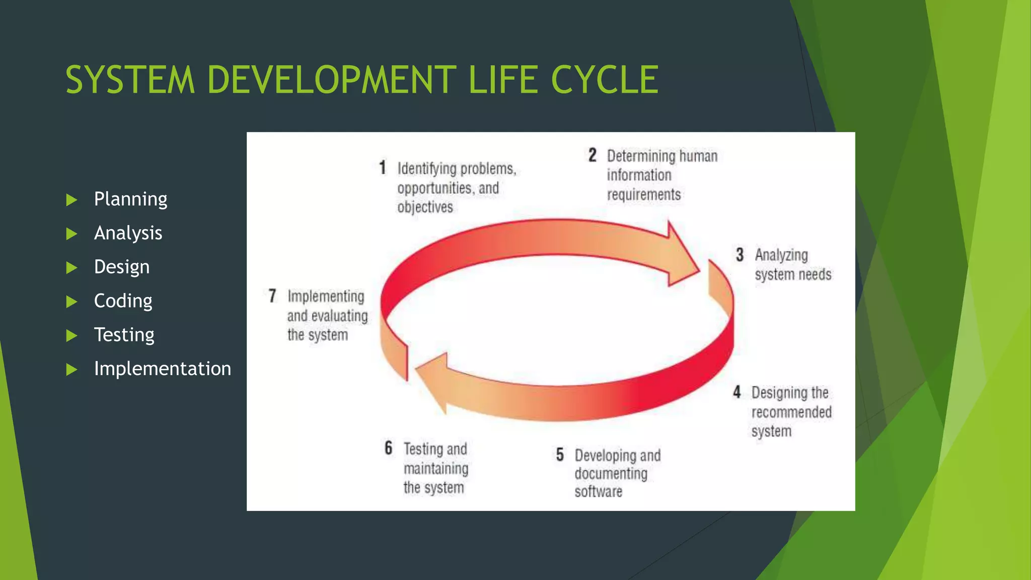
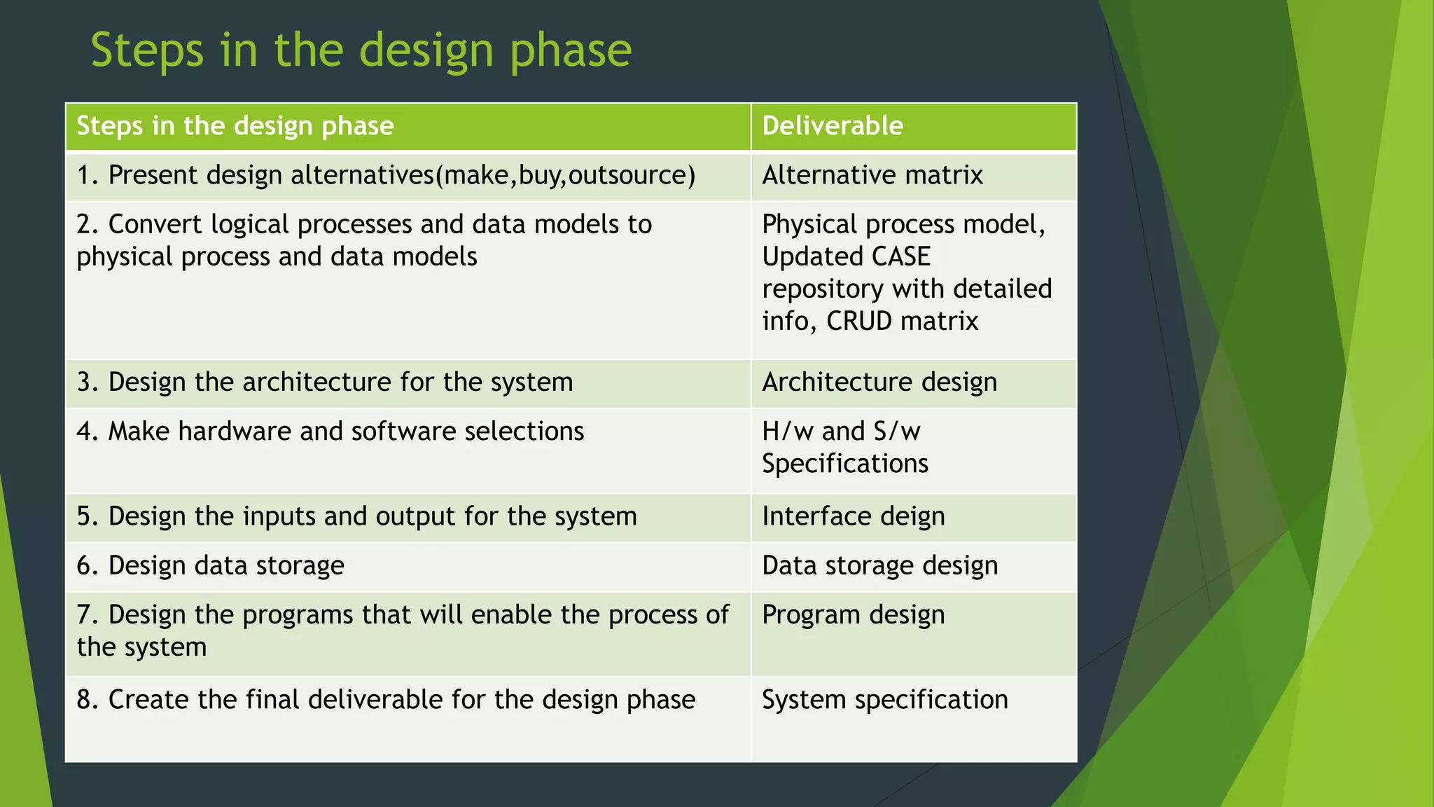
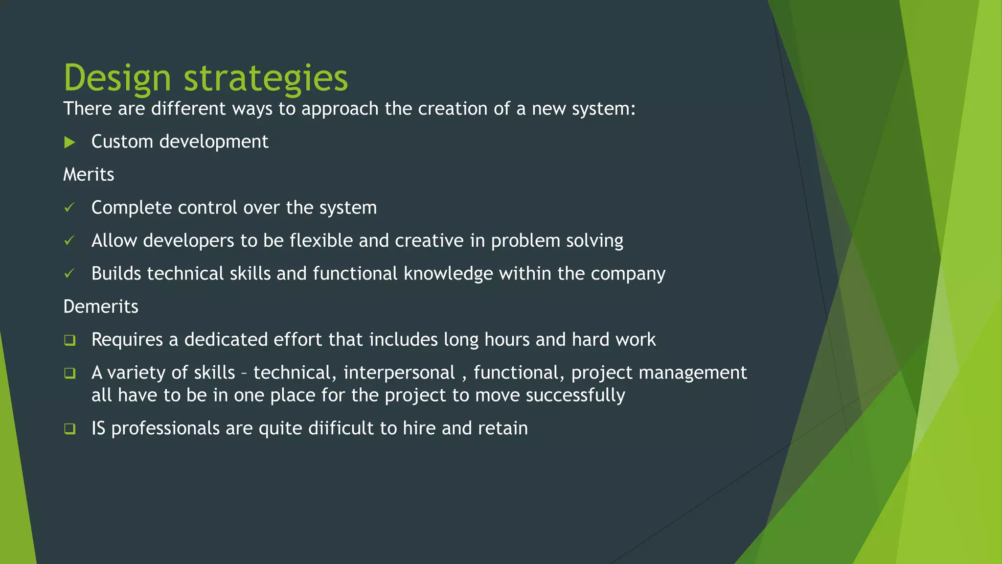
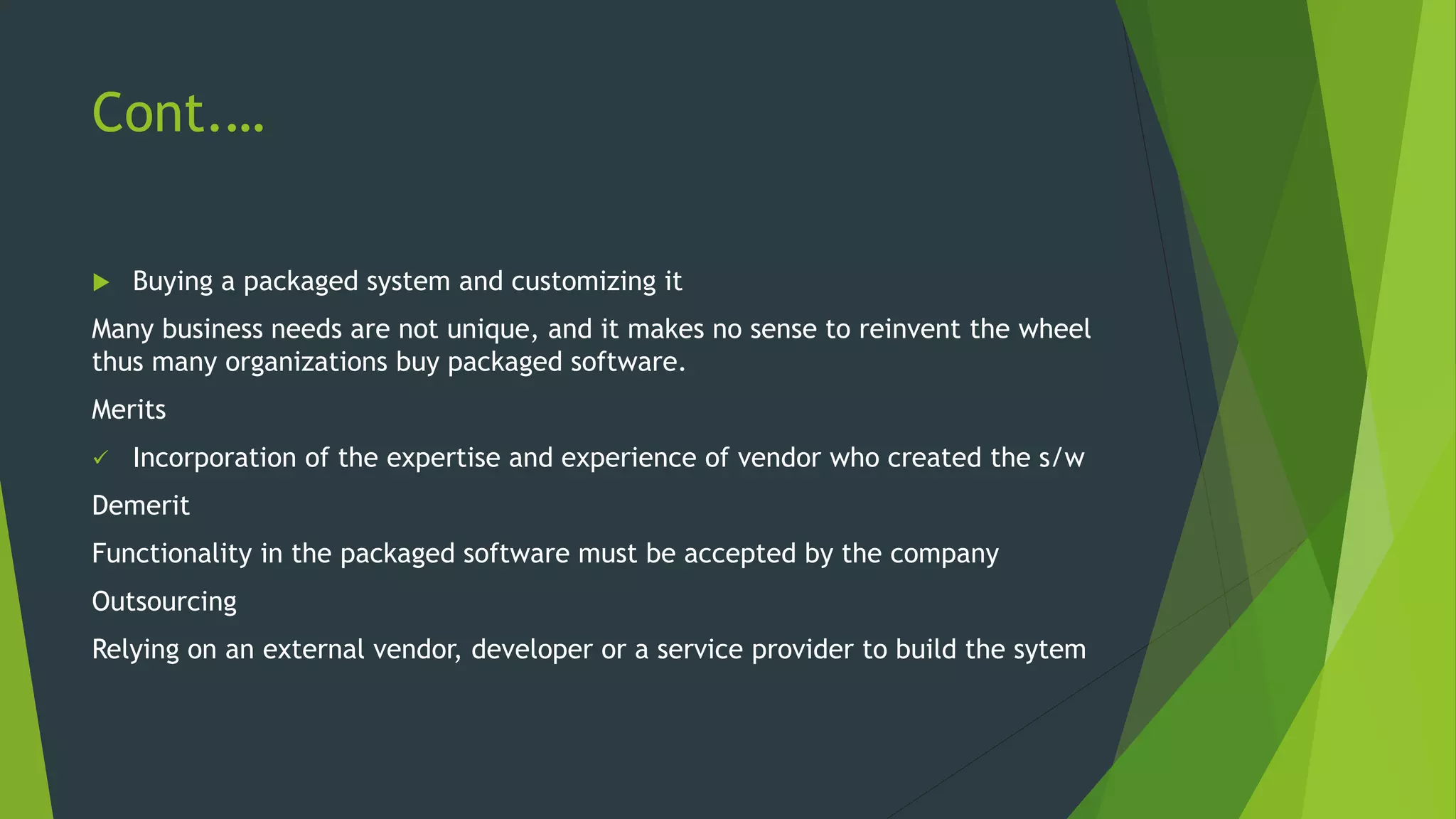
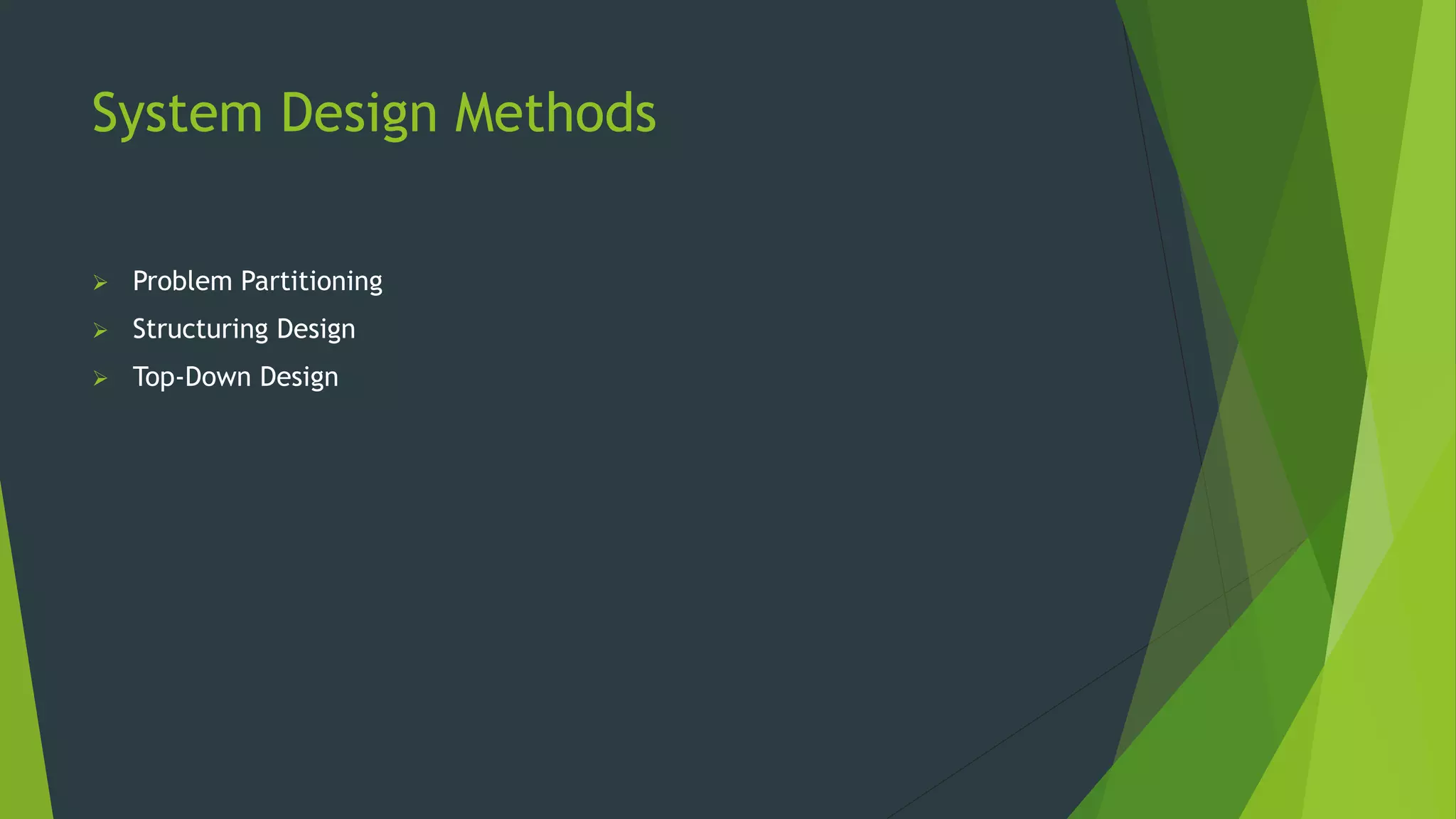
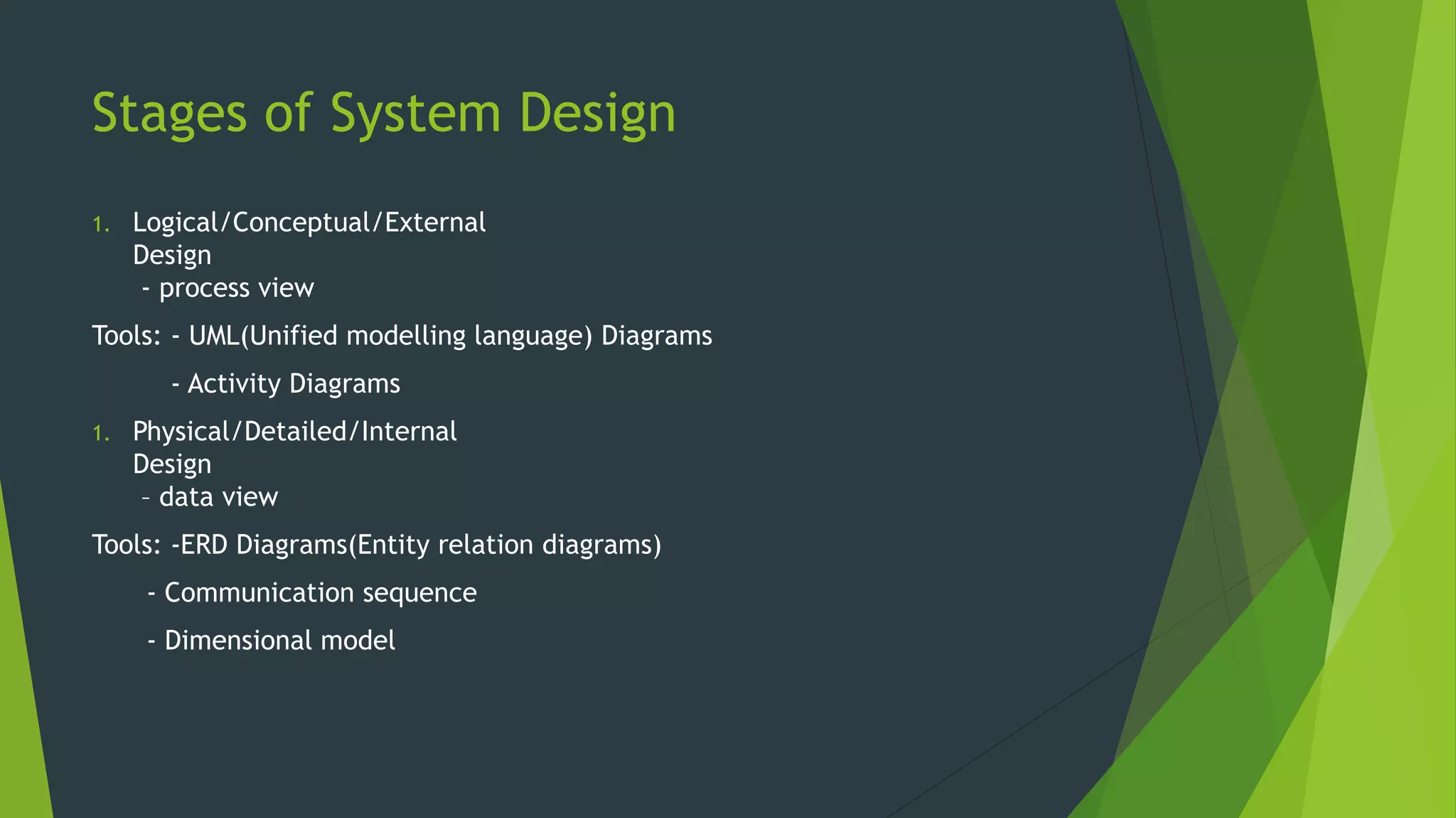
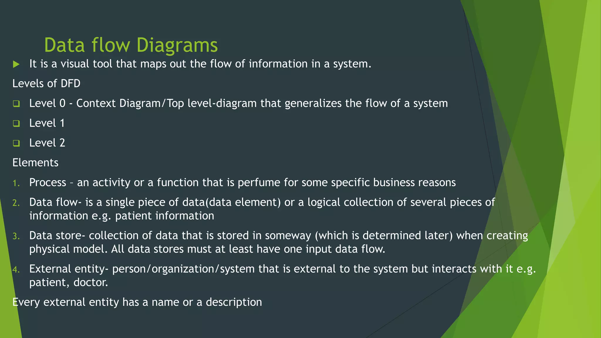
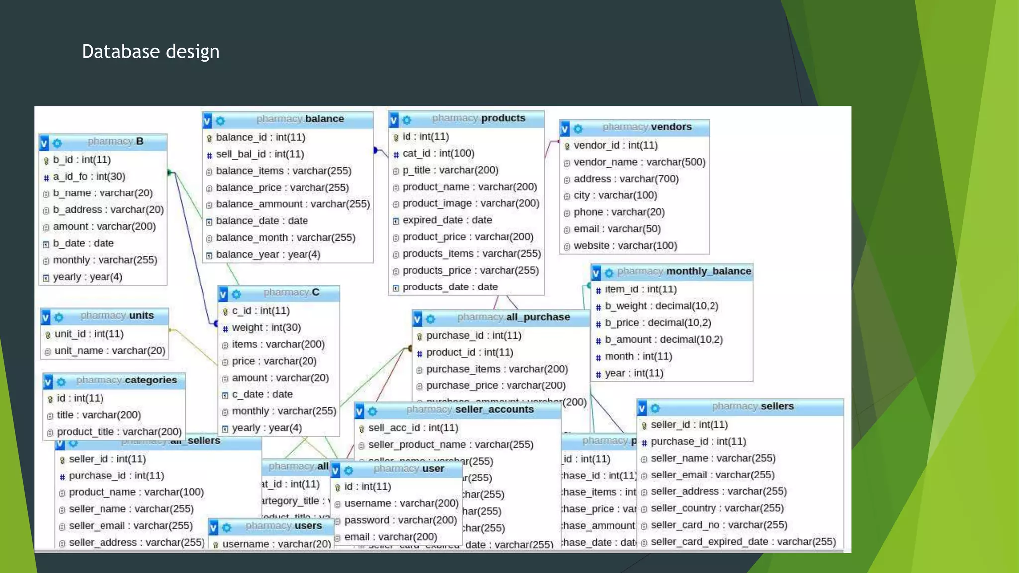
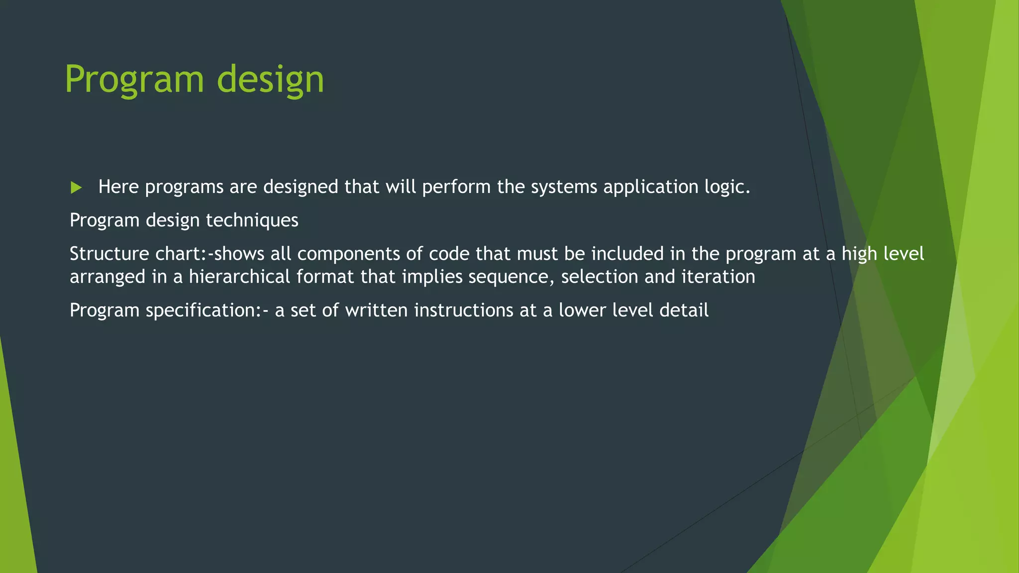
SYSTEM ANALYSIS AND
DESIGN
THE DESIGN PHASE
SYSTEM DEVELOPMENT LIFE CYCLE
 Planning
 Analysis
 Design
 Coding
 Testing
 Implementation
Design Phase
 It is a process of planning a new business system or replacing
an existing system by defining its components or modules to
satisfy the specific requirements. Before planning, you need to
understand the old system thoroughly and determine how
computers can best be used in order to operate efficiently
It uses the requirements that were gathered during the analysis to create a
blueprint for the future system.
Objectives of the Design Phase
 Support Business Activities
Ensure that User Requirements are Met
Provide Ease of Use
Specify the Logical Design Elements
Provide Software Specification
Conform to Design Standards
Steps in the design phase
Steps in the design phase Deliverable
1. Present design alternatives(make,buy,outsource) Alternative matrix
2. Convert logical processes and data models to
physical process and data models
Physical process model,
Updated CASE
repository with detailed
info, CRUD matrix
3. Design the architecture for the system Architecture design
4. Make hardware and software selections H/w and S/w
Specifications
5. Design the inputs and output for the system Interface deign
6. Design data storage Data storage design
7. Design the programs that will enable the process of
the system
Program design
8. Create the final deliverable for the design phase System specification
Design strategies
There are different ways to approach the creation of a new system:
 Custom development
Merits
 Complete control over the system
 Allow developers to be flexible and creative in problem solving
 Builds technical skills and functional knowledge within the company
Demerits
 Requires a dedicated effort that includes long hours and hard work
 A variety of skills – technical, interpersonal , functional, project management
all have to be in one place for the project to move successfully
 IS professionals are quite diificult to hire and retain
Cont.…
 Buying a packaged system and customizing it
Many business needs are not unique, and it makes no sense to reinvent the wheel
thus many organizations buy packaged software.
Merits
 Incorporation of the expertise and experience of vendor who created the s/w
Demerit
Functionality in the packaged software must be accepted by the company
Outsourcing
Relying on an external vendor, developer or a service provider to build the sytem
System Design Methods
 Problem Partitioning
 Structuring Design
 Top-Down Design
Stages of System Design
1. Logical/Conceptual/External
Design
- process view
Tools: - UML(Unified modelling language) Diagrams
- Activity Diagrams
1. Physical/Detailed/Internal
Design
– data view
Tools: -ERD Diagrams(Entity relation diagrams)
- Communication sequence
- Dimensional model
Logical/Conceptual/External
Design
 Deals with the process view
 Tools Used
 Unified Modelling Language(UML) Diagrams
 Developmental language that is intended to provide a standard way to
visualize the design of a system
Graphical representation of work flows
 Activity Diagrams
Used to describe the dynamic aspect of a system.
It is basically to represent the flow from one activity to another
Physical/Detailed/Internal
Design
Deals with the data view
Tools used:
 Entity relation Diagrams
It’s a snapshot of data structures
Shows entities(tables) in a database and relationship between
tables within that database
 Communication Sequence Diagram
Shows object interaction arranged in time sequence
 Dimensional model
 Database Design
Defines where data will be stored.
 A database should contain the following
 Primary keys
 Foreign keys
 Normalization
 Referential integrity
 Input and output design
Input- facilitates the entry of data into the system whether
highly structured data such information and unstructured
information.
Output- are the reports that the system produces whether on
the screen, paper or any other media such as the web.
 Architectural design
this is the conceptual model that defines the structure,
behavior, and more views of a system e.g. flow charts.
Also describes the hardware, software and network
infrastructure that will be used.
Avoiding classic design mistakes
1. Reducing design time: if time is short, there is a temptation to reduce the
time spent is such” unproductive activities "as design so that the team can jump
into “productive” programming. This results into missing important details that
have to be investigated later at a higher cost.
Solution: use rapid application development(RAD) techniques and timeboxing to
eliminate functionality or move into future version.
2. Feature creep: changes mostly scope creep, can significantly increase time
and cost.
Solution: ensure that all changes are vital and that the users are aware of the
impact on cost and time. Try to move proposed changes into future versions.
3. Switching tools in mid-project: sometimes analysts switch to what appears to
be a better tool during the design in the hopes of saving time or cost.
Solution: don’t switch or upgrade unless there is a compelling need for specific
features in the new tool, and then explicitly increase the schedule for including
learning time.
Data flow Diagrams
 It is a visual tool that maps out the flow of information in a system.
Levels of DFD
 Level 0 - Context Diagram/Top level-diagram that generalizes the flow of a system
 Level 1
 Level 2
Elements
1. Process – an activity or a function that is perfume for some specific business reasons
2. Data flow- is a single piece of data(data element) or a logical collection of several pieces of
information e.g. patient information
3. Data store- collection of data that is stored in someway (which is determined later) when creating
physical model. All data stores must at least have one input data flow.
4. External entity- person/organization/system that is external to the system but interacts with it e.g.
patient, doctor.
Every external entity has a name or a description
Level 0
Level 1
DFD
Context diagram
ENTITY RELATIONSHIP DIAGRAM
ERD is a picture that shows the information that is created, stored and used by a
business sytem.
Elements
Entity- is the basic building block for a data model
Attribute- type of information captured about an entity
Relationship – are associations between entities, and are lines that connects the
entities together
Cardinality- a ratio of parent instances to child instances
Modality- refers to whether or not an instance of a child entity can exists without
a related instance in the parent entity. Relationships have a cardinality of null or
not null.
Cont.….
ERD
Use case
Sequence diagram
ARCHITECTURE DESIGN
Describes system hardware, software and network environment
It flows from non-functional requirements, such as operational, performance,
security, cultural and political requirements.
Elements
 Architectural components
 Server based architecture
 Client- server architecture- Most preferred for costs reasons
 Client- server tiers
Creating an architecture design
Specifies the overall architecture and placement of software and hardware that will be used
Elements
A. Operational requirements
Specifies the environment in which the system must perform and how those may change over time.
1. Technical requirements- specifies the type of hardware and software on which the system will
work.
2. System integration requirement- are those that require the sytem to operate with other
information systems inside or outside the company
3. Portability requirements- information systems never remain constant.
4. Maintainability requirement- specifies the business requirement changes that can be anticipated.
Cont.…
B. Performance requirement
Focus on performance issues such as response time, capacity and reliability
i. Speed requirements- are exactly what they say: how fast should the system operate.
ii. Capacity requirements- Attempt to predict how many users the system will have to support.
iii. Availability and reliability requirements- the extent to which the system will be available to
the users and the permissible failure rate due to errors.
C. Security Requirements
Ability to protect the information system from disruption and data loss.
i. System value estimates.
ii. Access control requirements.
iii. Encryption and authentication requirement.
iv. Virus control requirement.
System Architecture
Cultural and Political Requirements
 Are those that are specific to the specific countries in which the system will
be used.
Hardware and Software Specifications
 Is a document that describes what hardware and software are required to
support the application.
User interface design
 This is the part of the system with which the users interact.
 It includes the screen display that provides navigation throughout the system,
the screens and forms that capture data and the reports that the system
produces.
Data storage design
Project team designs the data storage component of a system using a 2-step
approach:
1. Selecting the format of the data storage
2. Optimizing the format to perform efficiently
data storage format
i. Files
ii. databases
Database design
Program design
 Here programs are designed that will perform the systems application logic.
Program design techniques
Structure chart:-shows all components of code that must be included in the program at a high level
arranged in a hierarchical format that implies sequence, selection and iteration
Program specification:- a set of written instructions at a lower level detail
ANY
QUESTIONS??
System analysis and design

System analysis and design

  • 1.
  • 2.
    SYSTEM DEVELOPMENT LIFECYCLE  Planning  Analysis  Design  Coding  Testing  Implementation
  • 3.
    Design Phase  Itis a process of planning a new business system or replacing an existing system by defining its components or modules to satisfy the specific requirements. Before planning, you need to understand the old system thoroughly and determine how computers can best be used in order to operate efficiently It uses the requirements that were gathered during the analysis to create a blueprint for the future system.
  • 4.
    Objectives of theDesign Phase  Support Business Activities Ensure that User Requirements are Met Provide Ease of Use Specify the Logical Design Elements Provide Software Specification Conform to Design Standards
  • 5.
    Steps in thedesign phase Steps in the design phase Deliverable 1. Present design alternatives(make,buy,outsource) Alternative matrix 2. Convert logical processes and data models to physical process and data models Physical process model, Updated CASE repository with detailed info, CRUD matrix 3. Design the architecture for the system Architecture design 4. Make hardware and software selections H/w and S/w Specifications 5. Design the inputs and output for the system Interface deign 6. Design data storage Data storage design 7. Design the programs that will enable the process of the system Program design 8. Create the final deliverable for the design phase System specification
  • 6.
    Design strategies There aredifferent ways to approach the creation of a new system:  Custom development Merits  Complete control over the system  Allow developers to be flexible and creative in problem solving  Builds technical skills and functional knowledge within the company Demerits  Requires a dedicated effort that includes long hours and hard work  A variety of skills – technical, interpersonal , functional, project management all have to be in one place for the project to move successfully  IS professionals are quite diificult to hire and retain
  • 7.
    Cont.…  Buying apackaged system and customizing it Many business needs are not unique, and it makes no sense to reinvent the wheel thus many organizations buy packaged software. Merits  Incorporation of the expertise and experience of vendor who created the s/w Demerit Functionality in the packaged software must be accepted by the company Outsourcing Relying on an external vendor, developer or a service provider to build the sytem
  • 8.
    System Design Methods Problem Partitioning  Structuring Design  Top-Down Design
  • 9.
    Stages of SystemDesign 1. Logical/Conceptual/External Design - process view Tools: - UML(Unified modelling language) Diagrams - Activity Diagrams 1. Physical/Detailed/Internal Design – data view Tools: -ERD Diagrams(Entity relation diagrams) - Communication sequence - Dimensional model
  • 10.
    Logical/Conceptual/External Design  Deals withthe process view  Tools Used  Unified Modelling Language(UML) Diagrams  Developmental language that is intended to provide a standard way to visualize the design of a system Graphical representation of work flows  Activity Diagrams Used to describe the dynamic aspect of a system. It is basically to represent the flow from one activity to another
  • 11.
    Physical/Detailed/Internal Design Deals with thedata view Tools used:  Entity relation Diagrams It’s a snapshot of data structures Shows entities(tables) in a database and relationship between tables within that database  Communication Sequence Diagram Shows object interaction arranged in time sequence  Dimensional model  Database Design Defines where data will be stored.
  • 12.
     A databaseshould contain the following  Primary keys  Foreign keys  Normalization  Referential integrity  Input and output design Input- facilitates the entry of data into the system whether highly structured data such information and unstructured information. Output- are the reports that the system produces whether on the screen, paper or any other media such as the web.  Architectural design this is the conceptual model that defines the structure, behavior, and more views of a system e.g. flow charts. Also describes the hardware, software and network infrastructure that will be used.
  • 13.
    Avoiding classic designmistakes 1. Reducing design time: if time is short, there is a temptation to reduce the time spent is such” unproductive activities "as design so that the team can jump into “productive” programming. This results into missing important details that have to be investigated later at a higher cost. Solution: use rapid application development(RAD) techniques and timeboxing to eliminate functionality or move into future version. 2. Feature creep: changes mostly scope creep, can significantly increase time and cost. Solution: ensure that all changes are vital and that the users are aware of the impact on cost and time. Try to move proposed changes into future versions. 3. Switching tools in mid-project: sometimes analysts switch to what appears to be a better tool during the design in the hopes of saving time or cost. Solution: don’t switch or upgrade unless there is a compelling need for specific features in the new tool, and then explicitly increase the schedule for including learning time.
  • 14.
    Data flow Diagrams It is a visual tool that maps out the flow of information in a system. Levels of DFD  Level 0 - Context Diagram/Top level-diagram that generalizes the flow of a system  Level 1  Level 2 Elements 1. Process – an activity or a function that is perfume for some specific business reasons 2. Data flow- is a single piece of data(data element) or a logical collection of several pieces of information e.g. patient information 3. Data store- collection of data that is stored in someway (which is determined later) when creating physical model. All data stores must at least have one input data flow. 4. External entity- person/organization/system that is external to the system but interacts with it e.g. patient, doctor. Every external entity has a name or a description
  • 15.
  • 16.
  • 17.
  • 18.
  • 19.
    ENTITY RELATIONSHIP DIAGRAM ERDis a picture that shows the information that is created, stored and used by a business sytem. Elements Entity- is the basic building block for a data model Attribute- type of information captured about an entity Relationship – are associations between entities, and are lines that connects the entities together Cardinality- a ratio of parent instances to child instances Modality- refers to whether or not an instance of a child entity can exists without a related instance in the parent entity. Relationships have a cardinality of null or not null.
  • 20.
  • 21.
  • 22.
  • 23.
  • 25.
    ARCHITECTURE DESIGN Describes systemhardware, software and network environment It flows from non-functional requirements, such as operational, performance, security, cultural and political requirements. Elements  Architectural components  Server based architecture  Client- server architecture- Most preferred for costs reasons  Client- server tiers
  • 26.
    Creating an architecturedesign Specifies the overall architecture and placement of software and hardware that will be used Elements A. Operational requirements Specifies the environment in which the system must perform and how those may change over time. 1. Technical requirements- specifies the type of hardware and software on which the system will work. 2. System integration requirement- are those that require the sytem to operate with other information systems inside or outside the company 3. Portability requirements- information systems never remain constant. 4. Maintainability requirement- specifies the business requirement changes that can be anticipated.
  • 27.
    Cont.… B. Performance requirement Focuson performance issues such as response time, capacity and reliability i. Speed requirements- are exactly what they say: how fast should the system operate. ii. Capacity requirements- Attempt to predict how many users the system will have to support. iii. Availability and reliability requirements- the extent to which the system will be available to the users and the permissible failure rate due to errors. C. Security Requirements Ability to protect the information system from disruption and data loss. i. System value estimates. ii. Access control requirements. iii. Encryption and authentication requirement. iv. Virus control requirement.
  • 28.
  • 29.
    Cultural and PoliticalRequirements  Are those that are specific to the specific countries in which the system will be used.
  • 30.
    Hardware and SoftwareSpecifications  Is a document that describes what hardware and software are required to support the application.
  • 31.
    User interface design This is the part of the system with which the users interact.  It includes the screen display that provides navigation throughout the system, the screens and forms that capture data and the reports that the system produces.
  • 32.
    Data storage design Projectteam designs the data storage component of a system using a 2-step approach: 1. Selecting the format of the data storage 2. Optimizing the format to perform efficiently data storage format i. Files ii. databases
  • 33.
  • 34.
    Program design  Hereprograms are designed that will perform the systems application logic. Program design techniques Structure chart:-shows all components of code that must be included in the program at a high level arranged in a hierarchical format that implies sequence, selection and iteration Program specification:- a set of written instructions at a lower level detail
  • 35.