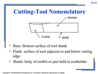
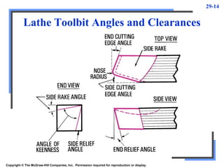
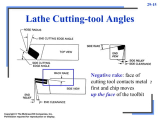
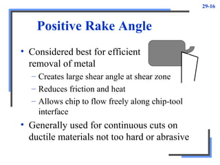
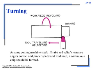
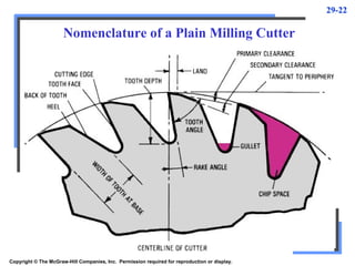
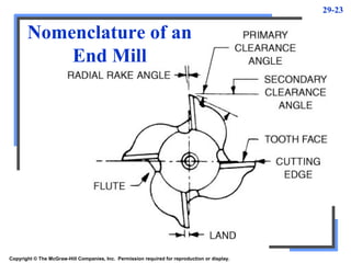
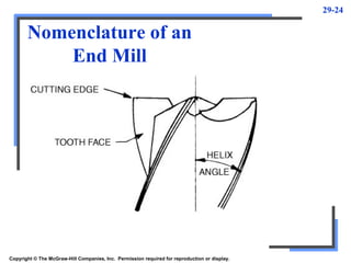
Copyright © The McGraw-Hill Companies, Inc.
Permission required for reproduction or display.
PowerPoint to accompany
Krar • Gill • Smid
Technology of Machine Tools
6th
Edition
Cutting Tools
Unit 29
29-2
Objectives
• Use the nomenclature of a cutting-tool point
• Explain the purpose of each type of rake and
clearance angle
• Identify the applications of various types of
cutting-tool materials
• Describe the cutting action of different types
of machines
29-3
Cutting Tools
• One of most important components in
machining process
• Performance will determine efficiency of
operation
• Two basic types (excluding abrasives)
– Single point and multi point
• Must have rake and clearance angles ground
or formed on them
29-4
Cutting-Tool Materials
• Lathe toolbits generally made of five
materials
– High-speed steel
– Cast alloys (such as stellite)
– Cemented carbides
– Ceramics
– Cermets
• More exotic finding wide use
– Borazon and polycrystalline diamond
29-5
Lathe Toolbit Properties
• Hard
• Wear-resistant
• Capable of maintaining a red hardness
during machining operation
– Red hardness: ability of cutting tool to
maintain sharp cutting edge even when turns
red because of high heat during cutting
• Able to withstand shock during cutting
• Shaped so edge can penetrate work
29-6
High-Speed Steel Toolbits
• May contain combinations of tungsten,
chromium, vanadium, molybdenum, cobalt
• Can take heavy cuts, withstand shock and
maintain sharp cutting edge under red heat
• Generally two types (general purpose)
– Molybdenum-base (Group M)
– Tungsten-base (Group T)
• Cobalt added if more red hardness desired
29-7
Cemented-Carbide Toolbits
• Capable of cutting speeds 3 to 4 times high-
speed steel toolbits
• Low toughness but high hardness and
excellent red-hardness
• Consist of tungsten carbide sintered in
cobalt matrix
• Straight tungsten used to machine cast iron
and nonferrous materials (crater easily)
• Different grades for different work
29-8
Coated Carbide Toolbits
• Made by depositing thin layer of wear-resistant
titanium nitride, titanium carbide or aluminum
oxide on cutting edge of tool
– Fused layer increases lubricity, improves cutting
edge wear resistance by 200%-500%
– Lowers breakage resistance up to 20%
– Provides longer life and increased cutting speeds
• Titanium-coated offer wear resistance at low
speeds, ceramic coated for higher speeds
29-9
Ceramic Toolbits
• Permit higher cutting speeds, increased tool
life and better surface finish than carbide
– Weaker than carbide used in shock-free or low-
shock situation
• Ceramic
– Heat-resistant material produced without metallic
bonding agent such as cobalt
– Aluminum oxide most popular additive
– Titanium oxide or Titanium carbide can be added
29-10
Diamond Toolbits
• Used mainly to machine nonferrous metals
and abrasive nonmetallics
• Single-crystal natural diamonds
– High-wear but low shock-resistant factors
• Polycrystalline diamonds
– Tiny manufactured diamonds fused together and
bonded to suitable carbide substrate
29-11
Cutting-Tool Nomenclature
• Cutting edge: leading edge of that does cutting
• Face: surface against which chip bears as it is
separated from work
• Nose: Tip of cutting tool formed by junction of
cutting edge and front face
Copyright © The McGraw-Hill Companies, Inc. Permission required for reproduction or display.
29-12
Cutting-Tool Nomenclature
• Nose radius: radius to which nose is ground
– Size of radius will affect finish
• Rough turning: small nose radius (.015in)
• Finish cuts: larger radius (.060 to .125 in.)
• Point: end of tool that has been ground for cutting
purposes
Copyright © The McGraw-Hill Companies, Inc. Permission required for reproduction or display.
29-13
Cutting-Tool Nomenclature
Copyright © The McGraw-Hill Companies, Inc. Permission required for reproduction or display.
• Base: Bottom surface of tool shank
• Flank: surface of tool adjacent to and below cutting
edge
• Shank: body of toolbit or part held in toolholder
29-14
Lathe Toolbit Angles and Clearances
Copyright © The McGraw-Hill Companies, Inc. Permission required for reproduction or display.
29-15
Lathe Cutting-tool Angles
Copyright © The McGraw-Hill Companies, Inc.
Permission required for reproduction or display.
Positive rake: point of
cutting tool and cutting edge
contact metal first and chip
moves down the face of
the toolbit
Negative rake: face of
cutting tool contacts metal
first and chip moves
up the face of the toolbit
29-16
Positive Rake Angle
• Considered best for efficient
removal of metal
– Creates large shear angle at shear zone
– Reduces friction and heat
– Allows chip to flow freely along chip-tool
interface
• Generally used for continuous cuts on
ductile materials not too hard or abrasive
29-17
Factors When Choosing Type and
Rake Angle for Cutting Tool
• Hardness of metal to be cut
• Type of cutting operation
– Continuous or interrupted
• Material and shape of cutting tool
• Strength of cutting edge
29-18
Shape of Chip
• Altered in number of ways to improve
cutting action and reduce amount of power
required
• Continuous straight ribbon chip can be
changed to continuous curled ribbon
– Changing angle of the keeness
• Included angle produced by grinding side rake
– Grinding chip breaker behind cutting edge of
toolbit
29-19
Tool Life
Copyright © The McGraw-Hill Companies, Inc.
Permission required for reproduction or display.
Occurs on side of cutting
edge as result of friction
between side of cutting-tool
edge and metal being
machined
When flank wear
is .015 to .030 in.
need to be reground
Nose wear occurs
as result of friction between
nose and metal being machined
Crater wear occurs as result
of chips sliding along
chip-tool interface,
result of built-up
edge on cutting
tool
29-20
Factors Affecting the Life of a
Cutting Tool
• Type of material being cut
• Microstructure of material
• Hardness of material
• Type of surface on metal (smooth or scaly)
• Material of cutting tool
• Profile of cutting tool
• Type of machining operation being performed
• Speed, feed, and depth of cut
29-21
Turning
Copyright © The McGraw-Hill Companies, Inc.
Permission required for reproduction or display.
Assume cutting machine steel: If rake and relief clearance
angles correct and proper speed and feed used, a continuous
chip should be formed.
29-22
Copyright © The McGraw-Hill Companies, Inc. Permission required for reproduction or display.
Nomenclature of a Plain Milling Cutter
29-23
Copyright © The McGraw-Hill Companies, Inc. Permission required for reproduction or display.
Nomenclature of an
End Mill
29-24
Nomenclature of an
End Mill
Copyright © The McGraw-Hill Companies, Inc. Permission required for reproduction or display.
29-25
Copyright © The McGraw-Hill Companies, Inc.
Permission required for reproduction or display.
Characteristics of a
Drill Point
Cutting-point angles for
standard drill
Chip formation
of a drill
Copyright © The McGraw-Hill Companies, Inc.
Permission required for reproduction or display.
PowerPoint to accompany
Krar • Gill • Smid
Technology of Machine Tools
6th
Edition
Operating Conditions
and Tool Life
Unit 30
30-27
Objectives
• Describe the effect of cutting conditions on
cutting-tool life
• Explain the effect of cutting conditions on
metal-removal rates
• State the advantages of new cutting-tool
materials
• Calculate the economic performance and
cost analysis for a machining operation
30-28
Operating Conditions
• Three operating variables influence metal-
removal rate and tool life
– Cutting speed
– Feed rate
– Depth of cut
30-29
Reduction in Tool Life
Operating Conditions
CUTTING
SPEED + 50%
FEED
RATE + 50%
DEPTH OF
CUT + 50%
90% 60% 15%
30-30
General Operating Condition Rules
• Proper cutting speed most critical factor to
consider establishing optimum conditions
– Too slow: Fewer parts produced, built-up edge
– Too fast: Tool breaks down quickly
• Optimum cutting speed should balance
metal-removal rate and cutting-tool life
• Choose heaviest depth of cut and feed rate
possible
Copyright © The McGraw-Hill Companies, Inc.
Permission required for reproduction or display.
PowerPoint to accompany
Krar • Gill • Smid
Technology of Machine Tools
6th
Edition
Carbide Cutting Tools
Unit 31
31-32
Objectives
• Identify and state the purpose of the two
main types of carbide grades
• Select the proper grade of carbide for
various workpiece materials
• Select the proper speeds and feeds for
carbide tools
31-33
Carbide Cutting Tools
• First used in Germany during WW II as
substitute for diamonds
• Various types of cemented (sintered)
carbides developed to suit different
materials and machining operations
– Good wear resistance
– Operate at speeds ranging 150 to 1200 sf/min
• Can machine metals at speeds that cause
cutting edge to become red hot without
loosing harness
31-34
Blending
• Five types of powders
– Tungsten carbide, titanium carbide, cobalt,
tantalum carbide, niobium carbide
• One or combination blended in different
proportions depending on grade desired
• Powder mixed in alcohol (24 to 190 h)
• Alcohol drained off
• Paraffin added to simplify pressing
operation
31-35
Compaction
Copyright © The McGraw-Hill Companies, Inc.
Permission required for reproduction or display.
• Must be molded to shape and size
• Five different methods to
compact powder
– Extrusion process
– Hot press
– Isostatic press
– Ingot press
– Pill press
• Green (pressed) compacts soft, must be
presintered to dissolve paraffin
31-36
Presintering
• Green compacts heated to about 1500º F in
furnace under protective atmosphere of
hydrogen
• Carbide blanks have consistency of chalk
• May be machined to required shape
– 40% oversize to allow for shrinkage that occurs
during final sintering
31-37
Sintering
• Last step in process
• Converts presintered machine blanks into
cemented carbide
• Carried out in either hydrogen atmosphere
or vacuum
– Temperatures between 2550º and 2730º F
• Binder (cobalt) unites and cements carbide
powders into dense structure of extremely
hard carbide crystals
31-38
Cemented-Carbide Applications
• Used extensively in manufacture of metal-
cutting tools
– Extreme hardness and good wear-resistance
• First used in machining operations as lathe
cutting tools
• Majority are single-point cutting tools used
on lathes and milling machines
31-39
Types of Carbide Lathe
Cutting Tools
• Brazed-tip type
– Cemented-carbide tips brazed to steel shanks
– Wide variety of styles and sizes
• Indexable insert type
– Throwaway inserts
– Wide variety of shapes: triangular, square,
diamond, and round
• Triangular: has three cutting edges
– Inserts held mechanically in special holder
31-40
Grades of Cemented Carbides
• Two main groups of carbides
– Straight tungsten carbide
• Contains only tungsten carbide and cobalt
• Strongest and most wear-resistant
• Used for machining cast iron and nonmetals
– Crater-resistant
• Contain titanium carbide and tantalum carbide in
addition to tungsten carbide and cobalt
• Used for machining most steels
31-41
Tool
Geometry
Copyright © The McGraw-Hill Companies, Inc.
Permission required for reproduction or display.
SIDE RELIEF
SIDE CLEARANCE
Terms adopted
by ASME
31-42
Cutting-Tool Terms
Copyright © The McGraw-Hill Companies, Inc.
Permission required for reproduction or display.
• Front, End, Relief
(Clearance)
– Allows end of cutting tool to
enter work
• Side Relief (Side)
– Permits side of tool to
advance into work
31-43
Cutting Speeds and Feeds
• Important factors that influence speeds,
feeds, and depth of cut
– Type and hardness of work material
– Grade and shape of cutting tool
– Rigidity of cutting tool
– Rigidity of work and machine
– Power rating of machine
Copyright © The McGraw-Hill Companies, Inc.
Permission required for reproduction or display.
PowerPoint to accompany
Krar • Gill • Smid
Technology of Machine Tools
6th
Edition
Cutting Fluids—Types
and Applications
Unit 34
34-45
Objectives
• State the importance and function of cutting
fluids
• Identify three types of cutting fluids and
state the purpose of each
• Apply cutting fluids efficiently for a variety
of machining operations
34-46
Cutting Fluids
• Essential in metal-cutting operations to
reduce heat and friction
• Centuries ago, water used on grindstones
• 100 years ago, tallow used (did not cool)
• Lard oils came later but turned rancid
• Early 20th
century saw soap added to water
• Soluble oils came in 1936
• Chemical cutting fluids introduced in 1944
34-47
Economic Advantages to Using
Cutting Fluids
• Reduction of tool costs
– Reduce tool wear, tools last longer
• Increased speed of production
– Reduce heat and friction so higher cutting speeds
• Reduction of labor costs
– Tools last longer and require less regrinding, less
downtime, reducing cost per part
• Reduction of power costs
– Friction reduced so less power required by
machining
34-48
Heat Generated During
Machining
• Heat find its way into one of three places
– Workpiece, tool, chips
Copyright © The McGraw-Hill Companies, Inc.
Permission required for reproduction or display.
Too much, work
will expand
Too much, cutting edge
will break down rapidly,
reducing tool life
Act as disposable
heat sink
34-49
Heat Dissipation
• Ideally most heat taken off in chips
• Indicated by change in chip color as heat
causes chips to oxidize
• Cutting fluids assist taking away heat
– Can dissipate at least 50% of heat created
during machining
34-50
Characteristics of a Good
Cutting Fluid
1. Good cooling capacity
2. Good lubricating
qualities
3. Resistance to
rancidity
4. Relatively low
viscosity
5. Stability (long life)
6. Rust resistance
7. Nontoxic
8. Transparent
9. Nonflammable
34-51
Types of Cutting Fluids
• Most commonly used cutting fluids
– Either aqueous based solutions or cutting oils
• Fall into three categories
– Cutting oils
– Emulsifiable oils
– Chemical (synthetic) cutting fluids
34-52
Oil Categories
• Sulfurized mineral oils
– Contain .5% to .8% sulfur
– Light-colored and transparent
– Stains copper and alloys
• Sulfochlorinated mineral oils
– 3% sulfur and 1% chlorine
– Prevent excessive built-up edges from forming
• Sulfochlorinated fatty oil blends
– Contain more sulfur than other types
34-53
Inactive Cutting Oils
• Oils will not darken copper strip immersed
in them for 3 hours at 212ºF
• Contained sulfur is natural
– Termed inactive because sulfur so firmly
attached to oil – very little released
• Four general categories
– Straight mineral oils, fatty oils, fatty and
mineral oil blends, sulfurized fatty-mineral oil
blend
34-54
Emulsifiable (Soluble) Oils
• Mineral oils containing soaplike material
that makes them soluble in water and causes
them to adhere to workpiece
• Emulsifiers break oil into minute particles
and keep them separated in water
– Supplied in concentrated form (1-5 /100 water)
• Good cooling and lubricating qualities
• Used at high cutting speeds, low cutting
pressures
34-55
Functions of a Cutting Fluid
• Prime functions
– Provide cooling
– Provide lubrication
• Other functions
– Prolong cutting-tool life
– Provide rust control
– Resist rancidity
34-56
Functions of a Cutting Fluid:
Cooling
• Heat has definite bearing on cutting-tool
wear
– Small reduction will greatly extend tool life
• Two sources of heat during cutting action
– Plastic deformation of metal
• Occurs immediately ahead of cutting tool
• Accounts for 2/3 to 3/4 of heat
– Friction from chip sliding along cutting-tool face
• Water most effective for reducing heat (rust)
34-57
Functions of a Cutting Fluid:
Lubrication
• Reduces friction between chip and tool face
– Shear plane becomes shorter
– Area where plastic deformation occurs
correspondingly smaller
• Extreme-pressure lubricants reduce amount
of heat-producing friction
• EP chemicals of synthetic fluids combine
chemically with sheared metal of chip to
form solid compounds (allow chip to slide)
34-58
Cutting-Tool Life
• Heat and friction prime causes of cutting-
tool breakdown
• Reduce temperature by as little as 50ºF, life
of cutting tool increases fivefold
• Built-up edge
– Pieces of metal weld themselves to tool face
– Becomes large and flat along tool face,
effective rake angle of cutting tool decreased
34-59
Application of Cutting Fluids
• Cutting-tool life and machining operations
influenced by way cutting fluid applied
• Copious stream under low pressure so work
and tool well covered
– Inside diameter of supply nozzle ¾ width of
cutting tool
– Applied to where chip being formed
34-60
Milling
Copyright © The McGraw-Hill Companies, Inc.
Permission required for reproduction or display.
• Face milling
– Ring-type distributor recommended to flood
cutter completely
– Keeps each tooth of cutter immersed in cutting
fluid at all times
• Slab milling
– Fluid directing to both
sides of cutter by fan-shaped
nozzles ¾ width of cutter

Cutting tools

  • 1.
    Copyright © TheMcGraw-Hill Companies, Inc. Permission required for reproduction or display. PowerPoint to accompany Krar • Gill • Smid Technology of Machine Tools 6th Edition Cutting Tools Unit 29
  • 2.
    29-2 Objectives • Use thenomenclature of a cutting-tool point • Explain the purpose of each type of rake and clearance angle • Identify the applications of various types of cutting-tool materials • Describe the cutting action of different types of machines
  • 3.
    29-3 Cutting Tools • Oneof most important components in machining process • Performance will determine efficiency of operation • Two basic types (excluding abrasives) – Single point and multi point • Must have rake and clearance angles ground or formed on them
  • 4.
    29-4 Cutting-Tool Materials • Lathetoolbits generally made of five materials – High-speed steel – Cast alloys (such as stellite) – Cemented carbides – Ceramics – Cermets • More exotic finding wide use – Borazon and polycrystalline diamond
  • 5.
    29-5 Lathe Toolbit Properties •Hard • Wear-resistant • Capable of maintaining a red hardness during machining operation – Red hardness: ability of cutting tool to maintain sharp cutting edge even when turns red because of high heat during cutting • Able to withstand shock during cutting • Shaped so edge can penetrate work
  • 6.
    29-6 High-Speed Steel Toolbits •May contain combinations of tungsten, chromium, vanadium, molybdenum, cobalt • Can take heavy cuts, withstand shock and maintain sharp cutting edge under red heat • Generally two types (general purpose) – Molybdenum-base (Group M) – Tungsten-base (Group T) • Cobalt added if more red hardness desired
  • 7.
    29-7 Cemented-Carbide Toolbits • Capableof cutting speeds 3 to 4 times high- speed steel toolbits • Low toughness but high hardness and excellent red-hardness • Consist of tungsten carbide sintered in cobalt matrix • Straight tungsten used to machine cast iron and nonferrous materials (crater easily) • Different grades for different work
  • 8.
    29-8 Coated Carbide Toolbits •Made by depositing thin layer of wear-resistant titanium nitride, titanium carbide or aluminum oxide on cutting edge of tool – Fused layer increases lubricity, improves cutting edge wear resistance by 200%-500% – Lowers breakage resistance up to 20% – Provides longer life and increased cutting speeds • Titanium-coated offer wear resistance at low speeds, ceramic coated for higher speeds
  • 9.
    29-9 Ceramic Toolbits • Permithigher cutting speeds, increased tool life and better surface finish than carbide – Weaker than carbide used in shock-free or low- shock situation • Ceramic – Heat-resistant material produced without metallic bonding agent such as cobalt – Aluminum oxide most popular additive – Titanium oxide or Titanium carbide can be added
  • 10.
    29-10 Diamond Toolbits • Usedmainly to machine nonferrous metals and abrasive nonmetallics • Single-crystal natural diamonds – High-wear but low shock-resistant factors • Polycrystalline diamonds – Tiny manufactured diamonds fused together and bonded to suitable carbide substrate
  • 11.
    29-11 Cutting-Tool Nomenclature • Cuttingedge: leading edge of that does cutting • Face: surface against which chip bears as it is separated from work • Nose: Tip of cutting tool formed by junction of cutting edge and front face Copyright © The McGraw-Hill Companies, Inc. Permission required for reproduction or display.
  • 12.
    29-12 Cutting-Tool Nomenclature • Noseradius: radius to which nose is ground – Size of radius will affect finish • Rough turning: small nose radius (.015in) • Finish cuts: larger radius (.060 to .125 in.) • Point: end of tool that has been ground for cutting purposes Copyright © The McGraw-Hill Companies, Inc. Permission required for reproduction or display.
  • 13.
    29-13 Cutting-Tool Nomenclature Copyright ©The McGraw-Hill Companies, Inc. Permission required for reproduction or display. • Base: Bottom surface of tool shank • Flank: surface of tool adjacent to and below cutting edge • Shank: body of toolbit or part held in toolholder
  • 14.
    29-14 Lathe Toolbit Anglesand Clearances Copyright © The McGraw-Hill Companies, Inc. Permission required for reproduction or display.
  • 15.
    29-15 Lathe Cutting-tool Angles Copyright© The McGraw-Hill Companies, Inc. Permission required for reproduction or display. Positive rake: point of cutting tool and cutting edge contact metal first and chip moves down the face of the toolbit Negative rake: face of cutting tool contacts metal first and chip moves up the face of the toolbit
  • 16.
    29-16 Positive Rake Angle •Considered best for efficient removal of metal – Creates large shear angle at shear zone – Reduces friction and heat – Allows chip to flow freely along chip-tool interface • Generally used for continuous cuts on ductile materials not too hard or abrasive
  • 17.
    29-17 Factors When ChoosingType and Rake Angle for Cutting Tool • Hardness of metal to be cut • Type of cutting operation – Continuous or interrupted • Material and shape of cutting tool • Strength of cutting edge
  • 18.
    29-18 Shape of Chip •Altered in number of ways to improve cutting action and reduce amount of power required • Continuous straight ribbon chip can be changed to continuous curled ribbon – Changing angle of the keeness • Included angle produced by grinding side rake – Grinding chip breaker behind cutting edge of toolbit
  • 19.
    29-19 Tool Life Copyright ©The McGraw-Hill Companies, Inc. Permission required for reproduction or display. Occurs on side of cutting edge as result of friction between side of cutting-tool edge and metal being machined When flank wear is .015 to .030 in. need to be reground Nose wear occurs as result of friction between nose and metal being machined Crater wear occurs as result of chips sliding along chip-tool interface, result of built-up edge on cutting tool
  • 20.
    29-20 Factors Affecting theLife of a Cutting Tool • Type of material being cut • Microstructure of material • Hardness of material • Type of surface on metal (smooth or scaly) • Material of cutting tool • Profile of cutting tool • Type of machining operation being performed • Speed, feed, and depth of cut
  • 21.
    29-21 Turning Copyright © TheMcGraw-Hill Companies, Inc. Permission required for reproduction or display. Assume cutting machine steel: If rake and relief clearance angles correct and proper speed and feed used, a continuous chip should be formed.
  • 22.
    29-22 Copyright © TheMcGraw-Hill Companies, Inc. Permission required for reproduction or display. Nomenclature of a Plain Milling Cutter
  • 23.
    29-23 Copyright © TheMcGraw-Hill Companies, Inc. Permission required for reproduction or display. Nomenclature of an End Mill
  • 24.
    29-24 Nomenclature of an EndMill Copyright © The McGraw-Hill Companies, Inc. Permission required for reproduction or display.
  • 25.
    29-25 Copyright © TheMcGraw-Hill Companies, Inc. Permission required for reproduction or display. Characteristics of a Drill Point Cutting-point angles for standard drill Chip formation of a drill
  • 26.
    Copyright © TheMcGraw-Hill Companies, Inc. Permission required for reproduction or display. PowerPoint to accompany Krar • Gill • Smid Technology of Machine Tools 6th Edition Operating Conditions and Tool Life Unit 30
  • 27.
    30-27 Objectives • Describe theeffect of cutting conditions on cutting-tool life • Explain the effect of cutting conditions on metal-removal rates • State the advantages of new cutting-tool materials • Calculate the economic performance and cost analysis for a machining operation
  • 28.
    30-28 Operating Conditions • Threeoperating variables influence metal- removal rate and tool life – Cutting speed – Feed rate – Depth of cut
  • 29.
    30-29 Reduction in ToolLife Operating Conditions CUTTING SPEED + 50% FEED RATE + 50% DEPTH OF CUT + 50% 90% 60% 15%
  • 30.
    30-30 General Operating ConditionRules • Proper cutting speed most critical factor to consider establishing optimum conditions – Too slow: Fewer parts produced, built-up edge – Too fast: Tool breaks down quickly • Optimum cutting speed should balance metal-removal rate and cutting-tool life • Choose heaviest depth of cut and feed rate possible
  • 31.
    Copyright © TheMcGraw-Hill Companies, Inc. Permission required for reproduction or display. PowerPoint to accompany Krar • Gill • Smid Technology of Machine Tools 6th Edition Carbide Cutting Tools Unit 31
  • 32.
    31-32 Objectives • Identify andstate the purpose of the two main types of carbide grades • Select the proper grade of carbide for various workpiece materials • Select the proper speeds and feeds for carbide tools
  • 33.
    31-33 Carbide Cutting Tools •First used in Germany during WW II as substitute for diamonds • Various types of cemented (sintered) carbides developed to suit different materials and machining operations – Good wear resistance – Operate at speeds ranging 150 to 1200 sf/min • Can machine metals at speeds that cause cutting edge to become red hot without loosing harness
  • 34.
    31-34 Blending • Five typesof powders – Tungsten carbide, titanium carbide, cobalt, tantalum carbide, niobium carbide • One or combination blended in different proportions depending on grade desired • Powder mixed in alcohol (24 to 190 h) • Alcohol drained off • Paraffin added to simplify pressing operation
  • 35.
    31-35 Compaction Copyright © TheMcGraw-Hill Companies, Inc. Permission required for reproduction or display. • Must be molded to shape and size • Five different methods to compact powder – Extrusion process – Hot press – Isostatic press – Ingot press – Pill press • Green (pressed) compacts soft, must be presintered to dissolve paraffin
  • 36.
    31-36 Presintering • Green compactsheated to about 1500º F in furnace under protective atmosphere of hydrogen • Carbide blanks have consistency of chalk • May be machined to required shape – 40% oversize to allow for shrinkage that occurs during final sintering
  • 37.
    31-37 Sintering • Last stepin process • Converts presintered machine blanks into cemented carbide • Carried out in either hydrogen atmosphere or vacuum – Temperatures between 2550º and 2730º F • Binder (cobalt) unites and cements carbide powders into dense structure of extremely hard carbide crystals
  • 38.
    31-38 Cemented-Carbide Applications • Usedextensively in manufacture of metal- cutting tools – Extreme hardness and good wear-resistance • First used in machining operations as lathe cutting tools • Majority are single-point cutting tools used on lathes and milling machines
  • 39.
    31-39 Types of CarbideLathe Cutting Tools • Brazed-tip type – Cemented-carbide tips brazed to steel shanks – Wide variety of styles and sizes • Indexable insert type – Throwaway inserts – Wide variety of shapes: triangular, square, diamond, and round • Triangular: has three cutting edges – Inserts held mechanically in special holder
  • 40.
    31-40 Grades of CementedCarbides • Two main groups of carbides – Straight tungsten carbide • Contains only tungsten carbide and cobalt • Strongest and most wear-resistant • Used for machining cast iron and nonmetals – Crater-resistant • Contain titanium carbide and tantalum carbide in addition to tungsten carbide and cobalt • Used for machining most steels
  • 41.
    31-41 Tool Geometry Copyright © TheMcGraw-Hill Companies, Inc. Permission required for reproduction or display. SIDE RELIEF SIDE CLEARANCE Terms adopted by ASME
  • 42.
    31-42 Cutting-Tool Terms Copyright ©The McGraw-Hill Companies, Inc. Permission required for reproduction or display. • Front, End, Relief (Clearance) – Allows end of cutting tool to enter work • Side Relief (Side) – Permits side of tool to advance into work
  • 43.
    31-43 Cutting Speeds andFeeds • Important factors that influence speeds, feeds, and depth of cut – Type and hardness of work material – Grade and shape of cutting tool – Rigidity of cutting tool – Rigidity of work and machine – Power rating of machine
  • 44.
    Copyright © TheMcGraw-Hill Companies, Inc. Permission required for reproduction or display. PowerPoint to accompany Krar • Gill • Smid Technology of Machine Tools 6th Edition Cutting Fluids—Types and Applications Unit 34
  • 45.
    34-45 Objectives • State theimportance and function of cutting fluids • Identify three types of cutting fluids and state the purpose of each • Apply cutting fluids efficiently for a variety of machining operations
  • 46.
    34-46 Cutting Fluids • Essentialin metal-cutting operations to reduce heat and friction • Centuries ago, water used on grindstones • 100 years ago, tallow used (did not cool) • Lard oils came later but turned rancid • Early 20th century saw soap added to water • Soluble oils came in 1936 • Chemical cutting fluids introduced in 1944
  • 47.
    34-47 Economic Advantages toUsing Cutting Fluids • Reduction of tool costs – Reduce tool wear, tools last longer • Increased speed of production – Reduce heat and friction so higher cutting speeds • Reduction of labor costs – Tools last longer and require less regrinding, less downtime, reducing cost per part • Reduction of power costs – Friction reduced so less power required by machining
  • 48.
    34-48 Heat Generated During Machining •Heat find its way into one of three places – Workpiece, tool, chips Copyright © The McGraw-Hill Companies, Inc. Permission required for reproduction or display. Too much, work will expand Too much, cutting edge will break down rapidly, reducing tool life Act as disposable heat sink
  • 49.
    34-49 Heat Dissipation • Ideallymost heat taken off in chips • Indicated by change in chip color as heat causes chips to oxidize • Cutting fluids assist taking away heat – Can dissipate at least 50% of heat created during machining
  • 50.
    34-50 Characteristics of aGood Cutting Fluid 1. Good cooling capacity 2. Good lubricating qualities 3. Resistance to rancidity 4. Relatively low viscosity 5. Stability (long life) 6. Rust resistance 7. Nontoxic 8. Transparent 9. Nonflammable
  • 51.
    34-51 Types of CuttingFluids • Most commonly used cutting fluids – Either aqueous based solutions or cutting oils • Fall into three categories – Cutting oils – Emulsifiable oils – Chemical (synthetic) cutting fluids
  • 52.
    34-52 Oil Categories • Sulfurizedmineral oils – Contain .5% to .8% sulfur – Light-colored and transparent – Stains copper and alloys • Sulfochlorinated mineral oils – 3% sulfur and 1% chlorine – Prevent excessive built-up edges from forming • Sulfochlorinated fatty oil blends – Contain more sulfur than other types
  • 53.
    34-53 Inactive Cutting Oils •Oils will not darken copper strip immersed in them for 3 hours at 212ºF • Contained sulfur is natural – Termed inactive because sulfur so firmly attached to oil – very little released • Four general categories – Straight mineral oils, fatty oils, fatty and mineral oil blends, sulfurized fatty-mineral oil blend
  • 54.
    34-54 Emulsifiable (Soluble) Oils •Mineral oils containing soaplike material that makes them soluble in water and causes them to adhere to workpiece • Emulsifiers break oil into minute particles and keep them separated in water – Supplied in concentrated form (1-5 /100 water) • Good cooling and lubricating qualities • Used at high cutting speeds, low cutting pressures
  • 55.
    34-55 Functions of aCutting Fluid • Prime functions – Provide cooling – Provide lubrication • Other functions – Prolong cutting-tool life – Provide rust control – Resist rancidity
  • 56.
    34-56 Functions of aCutting Fluid: Cooling • Heat has definite bearing on cutting-tool wear – Small reduction will greatly extend tool life • Two sources of heat during cutting action – Plastic deformation of metal • Occurs immediately ahead of cutting tool • Accounts for 2/3 to 3/4 of heat – Friction from chip sliding along cutting-tool face • Water most effective for reducing heat (rust)
  • 57.
    34-57 Functions of aCutting Fluid: Lubrication • Reduces friction between chip and tool face – Shear plane becomes shorter – Area where plastic deformation occurs correspondingly smaller • Extreme-pressure lubricants reduce amount of heat-producing friction • EP chemicals of synthetic fluids combine chemically with sheared metal of chip to form solid compounds (allow chip to slide)
  • 58.
    34-58 Cutting-Tool Life • Heatand friction prime causes of cutting- tool breakdown • Reduce temperature by as little as 50ºF, life of cutting tool increases fivefold • Built-up edge – Pieces of metal weld themselves to tool face – Becomes large and flat along tool face, effective rake angle of cutting tool decreased
  • 59.
    34-59 Application of CuttingFluids • Cutting-tool life and machining operations influenced by way cutting fluid applied • Copious stream under low pressure so work and tool well covered – Inside diameter of supply nozzle ¾ width of cutting tool – Applied to where chip being formed
  • 60.
    34-60 Milling Copyright © TheMcGraw-Hill Companies, Inc. Permission required for reproduction or display. • Face milling – Ring-type distributor recommended to flood cutter completely – Keeps each tooth of cutter immersed in cutting fluid at all times • Slab milling – Fluid directing to both sides of cutter by fan-shaped nozzles ¾ width of cutter

Editor's Notes

  • #15 The side cutting edge angle is the angle the cutting edge forms with the side of the tool shank (Fig. 29-4). Side cutting angles for a general-purpose lathe cutting tool may vary from 10° to 20°, depending on the material cut. If this angle is too large (over 30°), the tool will tend to chatter. The end cutting edge angle is the angle formed by the end cutting edge and a line at right angles to the centerline of the toolbit (Fig. 29-4). This angle may vary from 5° to 30°, depending on the type of cut and finish desired. An angle of 5° to 15° is satisfactory for roughing cuts; angles between 15° and 30° are used for general-purpose turning tools. The larger angle permits the cutting tool to be swiveled to the left for taking light cuts close to the dog or chuck, or when turning to a shoulder. The side relief (clearance) angle is the angle ground on the flank of the tool below the cutting edge (Figs. 29-4 and 29-5). This angle is generally 6° to 10°. The side clearance on a toolbit permits the cutting tool to advance lengthwise into the rotating work and prevents the flank from rubbing against the workpiece. The end relief (clearance) angle is the angle ground below the nose of the toolbit, which permits the cutting tool to be fed into the work. It is generally 10° to 15° for general-purpose tools (Figs. 29-4 and 29-5). This angle must be measured when the toolbit is held in the toolholder. The end relief angle varies with the hardness and type of material and the type of cut. The end relief angle is smaller for harder materials, providing support under the cutting edge. The side rake angle is the angle at which the face is ground away from the cutting edge. For general-purpose toolbits, the side rake is generally 14° (Figs. 29-4 and 29-5). Side rake creates a keener cutting edge and allows the chips to flow away quickly. For softer materials, the side rake angle is generally increased. Side rake may be either positive or negative, depending on the material being cut. The angle of keenness is the included angle produced by grinding side rake and side clearance on a toolbit (Fig. 29-4). This angle may be altered, depending on the type of material machined, and will be greater (closer to 90°) for harder materials. The back (top) rake angle is the backward slope of the tool face away from the nose. The back rake angle is generally about 20° and is provided for in the toolholder (Fig. 29-5). Back rake permits the chips to flow away from the point of the cutting tool. Two types of back or top rake angles are provided on cutting tools and are always found on the top of the toolbit: >Positive rake (Fig. 29-6a), where the point of the cutting tool and the cutting edge contact metal first and the chip moves down the face of the toolbit >Negative rake (Fig. 29-6b), where the face of the cutting tool contacts the metal first and the chip is forced up the face of the toolbit
  • #40 Indexable Inserts
  • #42 AATool Geometry The geometry of cutting tools refers to the various angles and clearances machined or ground on the tool faces. Although the terms and definitions relating to single-point cutting tools vary greatly, those adopted by the American Society of Mechanical Engineers (ASME) and currently in general use are illustrated in Fig. 31-6.