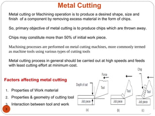
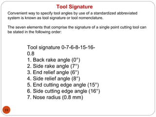
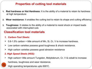
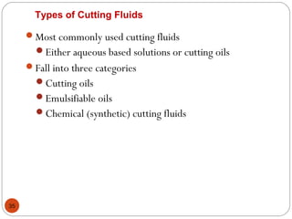
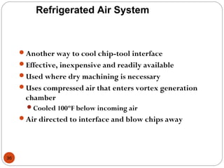
SlideShare a Scribd company logo
By
V. THULASIKANTH
Assistant Professor
Mechanical Engineering Department
vtkvsk@gmail.com
THEORY OF METAL CUTTING
1
Orthogonal and oblique cutting– Classification of cutting tools: single,
multipoint – Tool signature for single point cutting tool – Mechanics of
orthogonal cutting – Shear angle and its significance – Chip formation–
Cutting tool materials– Tool wear and tool life – Machinability – Cutting
Fluids– Simple problems.
Syllabus
2
TEXT BOOKS
1. Sharma, P.C., A textbook of Production Technology – Vol I and II, S. Chand &
Company Ltd., New Delhi, 1996.
2. Rao, P.N., Manufacturing Technology, Vol I & II, Tata McGraw Hill Publishing
Co., New Delhi, 1998.
Metal Cutting
3
Metal cutting or Machining operation is to produce a desired shape, size and
finish of a component by removing excess material in the form of chips.
So, primary objective of metal cutting is to produce chips which are thrown away.
Chips may constitute more than 50% of initial work piece.
Machining processes are performed on metal cutting machines, more commonly termed
as machine tools using various types of cutting tools
Metal cutting process in general should be carried out at high speeds and feeds
with least cutting effort at minimum cost.
Factors affecting metal cutting
1. Properties of Work material
2. Properties & geometry of cutting tool
3. Interaction between tool and work
4
External
Internal
threadingforminggroovingfacingturning
5
Mechanics of Metal Cutting
A cutting tool exerts compressive force on the workpiece which stresses the work
material beyond the yield point and therefore metal deform plastically and shears off.
Plastic flow takes place in a localized
region called the shear plane.
Sheared material begins to flow along
the cutting tool face in the form of chips.
Flowing chips cause tool wear.
Applied compressive force which leads
to formation of chips is called cutting
force.
Heat produced during shearing action raises the temperature of the workpeice,
cutting tool and chips.
Temperature rise in cutting tool softens and causes loss of keeness in cutting
edge.
Cutting force, heat and abrasive wear are important features in metal cutting.
6
7
Types of Metal Cutting Process
Orthogonal cutting is also known as two dimensional metal cutting in which the cutting
edge is normal to the work piece. (angle = 90deg)
Oblique cutting is also known as three dimensional cutting in which the cutting action
is inclined with the job by a certain angle called the inclination angle. (angle ≠ 90deg)
8
Types of Cutting Tools
Cutting tools performs the main machining operation.
It is a body having teeth or cutting edges on it.
They comprise of single point cutting tool or multipoint cutting tools.
Single point cutting tool : This type of tool has a effective cutting edge and
removes excess material from the workpeice along the cutting edge.
These tools may be left-handed or right-handed.
Again single point cutting tools classified as solid type and the tipped tool.
Brazed tools are generally known as tool bits and are used in tool holders.
The tipped type of tool is made from a good shank steel on which is mounted a tip
of cutting tool material.
Tip may be made of high speed steel or cemented carbide.
Different types of carbide tips are generally used on tipped tool.
9
Geometry comprises mainly of nose, rake face of the tool, flank, heel and shank etc.
The nose is shaped as conical with different angles.
10
Types of Chips
Chips are separated from the workpiece to impart the required size and shape.
The chips that are formed during metal cutting operations can be classified into four
types:
1. Continuous chips
2. Continuous chips with built-up edge
3. Discontinuous or segmental chips.
4. Non homogenous chips
1. Continuous chips
Chip is produced when there is low friction between the chip and tool face
This chip has the shape of long string or curls into a tight roll
Chip is produced when ductile materials such as Al, Cu, M.S, and wrought Iron are
machined.
Formation of very lengthy chip is hazardous to the machining process and the
machine operators.
11
It may wrap up on the cutting tool, work piece and interrupt in the cutting operation.
It becomes necessary to deform or break long continuous chips into small pieces.
It is done by using chip breakers and this can be an integral part of the tool design
or a separate device.
2. Continuous chips with built-up edge
When high friction exists between chip and tool, the chip material welds itself to the
tool face.
Welded material increases friction further which in turn leads to the building up a
layer upon layer of chip material.
Build up edge grows and breaks down when it becomes unstable.
Chips with build up edge result in higher power consumption, poor surface finish and
large tool wear
12
3. Discontinuous or segmental chips
Chip is produced in the form of small pieces.
These types of chips are obtained while
machining brittle material like cast iron, brass
and bronze at very low speeds and high feeds.
For brittle materials it is associated with fair
surface finish, lower power consumption and
reasonable tool life.
For ductile materials it is associated with poor surface finish excessive tool wear.
4. Non-homogeneous chips
It will be in the form of notches and formed due to non-uniform strain in materal
during chip formation.
Non homogenous chips are developed during machining highly hard alloys like
titanium.
13
Chip Control and Chip Breakers
During machining high tensile strength materials chips has to be properly
controlled.
Carbide tip tools will be used for high speeds which leads to high temperature and
produce continuous chips with blue color.
If the above mentioned chips are not broken means it will adversely effect the
machining in following ways,
•Spoiling cutting edge
•Raising temperature
•Poor surface finish
•Hazardous to machine operator
Two ways are employed to overcome all the above drawbacks.
First one is Proper selection of cutting conditions and second one is
chip breakers are used to break the chips.
14
Proper selection of cutting conditions
Since the cutting speed influences to the great extend the productivity of
machining and surface finish, working at low speeds may not be desirable.
 If the cutting speed is to be kept high, changing the feed and depth of cut is a
reasonable solution for chip control.
Chip breaker
There are two types of chip breakers
1.ΠExternal type, an inclined obstruction clamped to the tool face
2. Integral type, a groove ground into the tool face or bulges formed onto the tool
face
clamped
15
NOMENCLATURE Of SINGLE POINT TOOL
16
Feed
Back rake angle (αb)
It is the angle between the face of the tool and a line parallel with base of the tool
measured in a perpendicular plane through the side cutting edge.
This angle helps in removing the chips away from the work piece.
17
Side rake angle (αs)
It is the angle by which the face of tool is inclined side ways.
This angle of tool determines the thickness of the tool behind the cutting edge.
It is provided on tool to provide clearance between work piece and tool so as to
prevent the rubbing of work- piece with end flank of tool.
End relief angle
It is defined as the angle between the portion of the end flank immediately below
the cutting edge and a line perpendicular to the base of the tool, measured at right
angles to the flank.
It is the angle that allows the tool to cut without rubbing on the work- piece.
Side relief angle
It is the angle that prevents the interference as the tool enters the material.
It is the angle between the portion of the side flank immediately below the side
edge and a line perpendicular to the base of the tool measured at right angles to
the side.
18
End cutting edge angle
It is the angle between the end cutting edge and a line perpendicular to the shank
of the tool.
It provides clearance between tool cutting edge and work piece.
Side cutting edge angle
It is the angle between straight cutting edge on the side of tool and the side of the
shank.
It is also known as lead angle.
It is responsible for turning the chip away from the finished surface.
19
Tool Signature
Convenient way to specify tool angles by use of a standardized abbreviated
system is known as tool signature or tool nomenclature.
The seven elements that comprise the signature of a single point cutting tool can
be stated in the following order:
Tool signature 0-7-6-8-15-16-
0.8
1. Back rake angle (0°)
2. Side rake angle (7°)
3. End relief angle (6°)
4. Side relief angle (8°)
5. End cutting edge angle (15°)
6. Side cutting edge angle (16°)
7. Nose radius (0.8 mm)
20
Properties of cutting tool materials
1. Red hardness or Hot Hardness: It is the ability of a material to retain its hardness
at high temperature
2. Wear resistance: It enables the cutting tool to retain its shape and cutting efficiency
3. Toughness: It relates to the ability of a material to resist shock or impact loads
associated with interrupted cuts
Classification tool materials
1. Carbon-Tool Steels:
 0.6-1.5% carbon + little amount of Mn, Si, Cr, V to increase hardness.
 Low carbon varieties possess good toughness & shock resistance.
 High carbon varieties possess good abrasion resistance
2. High Speed Steels (HSS):
 High carbon+ little amount Tungsten, Molybdenum, Cr, V & cobalt to increase
hardness, toughness and wear résistance.
 High operating temperatures upto 600o
C.
21
 Two types of HSS i.e, is T-type and M-Type
 Vanadium increases abrasion resistance but higher percentage will decreases
grindability.
 Chromium increases hardenability
 Cobalt is added to HSS to increase red hardness.
3. Cast Cobalt Base Alloys:
 It is a combination of W, Cr, carbon and Cobalt which form an alloy with red
hardness, wear resistance and toughness. It is prepare by casting.
 Used for machining Cast iron, alloy steels, non-ferrous metals and super alloys
4. Cemented Carbides:
 These are carbides of W, Titanium and tantalum with small amount of cobalt
produced by means of powder metallurgy route.
 Two types i.e, Straight Tungsten Carbide Cobalt Grade and Alloyed Tungsten
Carbide Grade
22
Straight Tungsten Carbide Cobalt Grade : Cast iron, non ferrous alloys, plastics,
wood, glass etc.
Alloyed Tungsten Carbide Grade: All grades of steel at 3 to 4 times more speeds
than HSS
5. Ceramic Tools:
 Aluminium Oxide, Silicon Carbide, Boron Carbide, Titanium Carbide, Titanium
Boride
 High speed, longer tool life, superior surface finish, No coolant is required.
6. Diamond Tools:
 More abrasion resistance
 Used for turning grinding wheels
 Used to produce mirror surface finish.
 Diamond abrassive belts are used to produce TV screens
 Poly crystalline diamond inserts are brazed into cutting edges of circular saws for
cutting construction materials like concrete, refractories, stone etc.
23
Tool Life
Properly designed and ground cutting tool is expected to perform the metal cutting
operation in an effective an smooth manner
If a tool is not giving satisfactory performance it is an indicative of tool failure.
Following are the adverse effects observed during operation;
During operation cutting tool may fail due to following;
Extremely poor surface finish on the workpiece
Higher consumption of power
Work dimensions are not produced as specified
Overheating of cutting tool
Appearance of burnishing band on the work surface
Thermal cracking and softening
Mechanical Chipping
Gradual wear
24
1.Thermal Cracking and Softening
During cutting operation lot of heat will be generated due to this cutting tool tip
and area closer to cutting edge will become hot.
Cutting tool material will be harder up to certain limit (temperature & pressure), if
it crosses the limit it starts deforming plastically at tip and adjacent to the cutting
edge under the action of cutting pressure and high temperature.
Tool looses its cutting ability and it is said to have failed due to softening.
Main factors responsible for this condition are;
High cutting speed
High feed rate
More depth of cut
Small nose radius
Choice of wrong tool material
Tool life is defined as the time interval for which tool works satisfactorily
between two successive grinding or re-sharpening of the tool.
25
Working temperatures for common tool materials are;
Carbon tool steels 200o
C - 250o
C
High speed steel 560o
C - 600o
C
Cemented Carbides 800o
C - 1000o
C
Tool material is subjected to local expansion and contraction due to severe
temperature gradient.
Gives rise to thermal stresses further leads to thermal cracks.
26
2. Mechanical Chipping
Mechanical chipping of nose an cutting edge of the tool are commonly observed
causes for tool failure.
Reasons for failure are High cutting pressure, Mechanical impact, Excessive
wear, too high vibrations and chatter, weak tip an cutting edge, etc.
This type of failure is pronounced in carbide tipped and diamond tools due to
high brittleness of tool material.
Chipped Tip
27
3. Gradual wear
When a tool is in use for some time it is found to have lost some weight or
mass implying that it has lost some material from it due to wear.
Wear locations:
Crater wear location
Flank wear location
Crater wear
Due to pressure of the hot chip
sliding up the face of the tool, crater
or a depression is formed on the face
of tool. (Ductile materials)
By diffusion shape of crater formed
corresponds to the shape of
Crater wear
28
Flank wear
Occurs between tool and workpiece
interface
Due to abrasion between tool flank
and workpiece
Hard microconstituents of cut
material and broken parts of BUE.
Common in Brittle material.
The entire area subjected to flank
wear is known as WEAR LAND (VB),
occurs on tool nose, front and side
relief faces
29
Mechanism of wear
Adhesion wear: Fragments of the work-piece get welded to the tool
surface at high temperatures; eventually, they break off, tearing
small parts of the tool with them.
• Abrasion: Hard particles, microscopic variations on the bottom
surface of the chips rub against the tool surface and break away a
fraction of tool with them.
• Diffusion wear: At high temperatures, atoms from tool diffuse
across to the chip; the rate of diffusion increases exponentially with
temperature; this reduces the fracture strength of the crystals.
•Chemical wear: Reaction of cutting fluid to material of tool
30
Heat Generated During Machining
Heat finds its way into one of three places
Workpiece, tool and chips
Heat Dissipation
Ideally most heat taken off in chips
Indicated by change in chip color as heat causes chips to
oxidize
Cutting fluids assist taking away heat
Can dissipate at least 50% of heat created during machining
31
Cutting Fluids—Types and Applications
Cutting Fluids
Essential in metal-cutting operations to reduce heat and friction
Centuries ago, water used on grindstones
100 years ago, tallow used (did not cool)
Lard oils came later but turned rancid
Early 20th
century saw soap added to water
Soluble oils came in 1936
Chemical cutting fluids introduced in 1944
32
Cutting fluid is a type of coolant and lubricant designed specifically for
metalworking and machining processes.
There are various kinds of cutting fluids, which include oils, oil-water emulsions,
pastes, gels, aerosols (mists), and air or other gases.
 They may be made from petroleum distillates, animal fats, plant oils, water and
air, or other raw ingredients.
Depending on context and on which type of cutting fluid is being considered, it
may be referred to as cutting fluid, cutting oil, cutting compound, coolant, or
lubricant.
What is Cutting Fluid ?
33
Economic Advantages to Using Cutting Fluids
Reduction of tool costs
Reduce tool wear, tools last longer
Increased speed of production
Reduce heat and friction so higher cutting speeds
Reduction of labor costs
Tools last longer and require less regrinding, less downtime, reducing
cost per part
Reduction of power costs
Friction reduced so less power required by machining
34
Characteristics of a Good Cutting Fluid
Good cooling capacity
Good lubricating qualities
Resistance to rancidity
Relatively low viscosity
Stability (long life)
Rust resistance
Nontoxic
Transparent
Nonflammable
35
Types of Cutting Fluids
Most commonly used cutting fluids
Either aqueous based solutions or cutting oils
Fall into three categories
Cutting oils
Emulsifiable oils
Chemical (synthetic) cutting fluids
36
Refrigerated Air System
Another way to cool chip-tool interface
Effective, inexpensive and readily available
Used where dry machining is necessary
Uses compressed air that enters vortex generation
chamber
Cooled 100ºF below incoming air
Air directed to interface and blow chips away
37
38

More Related Content

What's hot

Machining operations and machine tools
Machining operations and machine toolsMachining operations and machine tools
Machining operations and machine tools
Muhammad Muddassir
 
Sheet Metal Forming
Sheet Metal FormingSheet Metal Forming
Sheet Metal Forming
vins049
 
Super finishing Processes
Super finishing ProcessesSuper finishing Processes
Super finishing Processes
VIMAL GOTECHA VLG.
 
Coining process
Coining processCoining process
Coining process
Avinash Navin
 
Grinding
GrindingGrinding
Single Point Cutting Tools
Single Point Cutting ToolsSingle Point Cutting Tools
Single Point Cutting Tools
GIRISH SURVE
 
Grinding machine
Grinding machineGrinding machine
Grinding machine
mohammed tayeeb
 
Grinding wheel designation and selection
Grinding wheel designation and selectionGrinding wheel designation and selection
Grinding wheel designation and selection
cpandiv
 
gear and thread manufacturing,metal cutting,manufacturing processes,Productio...
gear and thread manufacturing,metal cutting,manufacturing processes,Productio...gear and thread manufacturing,metal cutting,manufacturing processes,Productio...
gear and thread manufacturing,metal cutting,manufacturing processes,Productio...
Prof.Mayur Modi
 
Surface texture
Surface textureSurface texture
Surface texture
GAURAVBHARDWAJ160
 
Orthogonal & oblique cutting
Orthogonal & oblique cuttingOrthogonal & oblique cutting
Orthogonal & oblique cutting
Shivam Kumar
 
Lathe operations
Lathe operationsLathe operations
Lathe operations
DEBOLINAMUKHERJEE7
 
Milling machine(husain)
Milling machine(husain)Milling machine(husain)
Milling machine(husain)
husain252
 
Unit 3-METAL FORMING PROCESSES
Unit 3-METAL FORMING PROCESSESUnit 3-METAL FORMING PROCESSES
Lathe machine
Lathe machineLathe machine
Lathe machine
Raju D
 
Forging
ForgingForging
Milling Fixture
Milling FixtureMilling Fixture
Milling Fixture
Amruta Rane
 
Forming process forging
Forming process forgingForming process forging
Forming process forging
N.Prakasan
 
METAL CUTTING
METAL CUTTINGMETAL CUTTING
METAL CUTTING
Kunj Thummar
 
Screw thread measurement
Screw thread measurementScrew thread measurement
Screw thread measurement
Chintan Mehta
 

What's hot (20)

Machining operations and machine tools
Machining operations and machine toolsMachining operations and machine tools
Machining operations and machine tools
 
Sheet Metal Forming
Sheet Metal FormingSheet Metal Forming
Sheet Metal Forming
 
Super finishing Processes
Super finishing ProcessesSuper finishing Processes
Super finishing Processes
 
Coining process
Coining processCoining process
Coining process
 
Grinding
GrindingGrinding
Grinding
 
Single Point Cutting Tools
Single Point Cutting ToolsSingle Point Cutting Tools
Single Point Cutting Tools
 
Grinding machine
Grinding machineGrinding machine
Grinding machine
 
Grinding wheel designation and selection
Grinding wheel designation and selectionGrinding wheel designation and selection
Grinding wheel designation and selection
 
gear and thread manufacturing,metal cutting,manufacturing processes,Productio...
gear and thread manufacturing,metal cutting,manufacturing processes,Productio...gear and thread manufacturing,metal cutting,manufacturing processes,Productio...
gear and thread manufacturing,metal cutting,manufacturing processes,Productio...
 
Surface texture
Surface textureSurface texture
Surface texture
 
Orthogonal & oblique cutting
Orthogonal & oblique cuttingOrthogonal & oblique cutting
Orthogonal & oblique cutting
 
Lathe operations
Lathe operationsLathe operations
Lathe operations
 
Milling machine(husain)
Milling machine(husain)Milling machine(husain)
Milling machine(husain)
 
Unit 3-METAL FORMING PROCESSES
Unit 3-METAL FORMING PROCESSESUnit 3-METAL FORMING PROCESSES
Unit 3-METAL FORMING PROCESSES
 
Lathe machine
Lathe machineLathe machine
Lathe machine
 
Forging
ForgingForging
Forging
 
Milling Fixture
Milling FixtureMilling Fixture
Milling Fixture
 
Forming process forging
Forming process forgingForming process forging
Forming process forging
 
METAL CUTTING
METAL CUTTINGMETAL CUTTING
METAL CUTTING
 
Screw thread measurement
Screw thread measurementScrew thread measurement
Screw thread measurement
 

Viewers also liked

Theory of metal cutting
Theory of metal cuttingTheory of metal cutting
Theory of metal cutting
Muhammad Muddassir
 
Mechanics of metal cutting
Mechanics of metal cuttingMechanics of metal cutting
Mechanics of metal cuttingmanoj18biet
 
Theory of-metal-cutting
Theory of-metal-cuttingTheory of-metal-cutting
Theory of-metal-cutting
Gaurav Gunjan
 
Merchant's circle
Merchant's circleMerchant's circle
Merchant's circle
Sumit Shrivastava
 
azad alam alig
 azad alam alig azad alam alig
azad alam alig
azadalig
 
Theory of metal cutting
Theory of metal cuttingTheory of metal cutting
Theory of metal cuttingraajeeradha
 
Metal cutting 1
Metal cutting 1Metal cutting 1
Metal cutting 1
Naman Dave
 
Tool wear & Tool life / Machinability / Surface roughness
Tool wear & Tool life / Machinability / Surface roughnessTool wear & Tool life / Machinability / Surface roughness
Tool wear & Tool life / Machinability / Surface roughness
gosaliya dheirya
 
Tool wear, tool life & machinability
Tool wear, tool life & machinabilityTool wear, tool life & machinability
Tool wear, tool life & machinability
DENNY OTTARACKAL
 
Lecture 3 theory of metal cutting
Lecture 3  theory of metal cuttingLecture 3  theory of metal cutting
Lecture 3 theory of metal cuttingVJTI Production
 
Single point cutting tool
Single point cutting toolSingle point cutting tool
Single point cutting tool
samayadtime
 
Theory of metal cutting-module II
Theory of metal cutting-module IITheory of metal cutting-module II
Theory of metal cutting-module II
Dr. Rejeesh C R
 
Finite Element Simulation Analysis of Three-Dimensional Cutting Process Based...
Finite Element Simulation Analysis of Three-Dimensional Cutting Process Based...Finite Element Simulation Analysis of Three-Dimensional Cutting Process Based...
Finite Element Simulation Analysis of Three-Dimensional Cutting Process Based...
IJRES Journal
 
Merchants circle-diagram
Merchants circle-diagramMerchants circle-diagram
Merchants circle-diagram
cpandiv
 
Mtt114 lesson 1 introduction
Mtt114 lesson 1 introductionMtt114 lesson 1 introduction
Mtt114 lesson 1 introduction
Elizabethtown Community and Technical College
 
Moduleii 140313022420-phpapp01
Moduleii 140313022420-phpapp01Moduleii 140313022420-phpapp01
Moduleii 140313022420-phpapp01
manojkumarg1990
 
Cutting temperature
Cutting temperatureCutting temperature
Cutting temperature
lijo621
 
SFD & BMD
SFD & BMDSFD & BMD
SFD & BMD
Ravi Vishwakarma
 
Tool materials and tool wear
Tool materials and tool wearTool materials and tool wear
Tool materials and tool wearVJTI Production
 

Viewers also liked (20)

Theory of metal cutting
Theory of metal cuttingTheory of metal cutting
Theory of metal cutting
 
Mechanics of metal cutting
Mechanics of metal cuttingMechanics of metal cutting
Mechanics of metal cutting
 
Theory of-metal-cutting
Theory of-metal-cuttingTheory of-metal-cutting
Theory of-metal-cutting
 
Merchant's circle
Merchant's circleMerchant's circle
Merchant's circle
 
azad alam alig
 azad alam alig azad alam alig
azad alam alig
 
Theory of metal cutting
Theory of metal cuttingTheory of metal cutting
Theory of metal cutting
 
Metal cutting 1
Metal cutting 1Metal cutting 1
Metal cutting 1
 
Tool wear & Tool life / Machinability / Surface roughness
Tool wear & Tool life / Machinability / Surface roughnessTool wear & Tool life / Machinability / Surface roughness
Tool wear & Tool life / Machinability / Surface roughness
 
Tool wear, tool life & machinability
Tool wear, tool life & machinabilityTool wear, tool life & machinability
Tool wear, tool life & machinability
 
Lecture 3 theory of metal cutting
Lecture 3  theory of metal cuttingLecture 3  theory of metal cutting
Lecture 3 theory of metal cutting
 
Single point cutting tool
Single point cutting toolSingle point cutting tool
Single point cutting tool
 
Theory of metal cutting-module II
Theory of metal cutting-module IITheory of metal cutting-module II
Theory of metal cutting-module II
 
Finite Element Simulation Analysis of Three-Dimensional Cutting Process Based...
Finite Element Simulation Analysis of Three-Dimensional Cutting Process Based...Finite Element Simulation Analysis of Three-Dimensional Cutting Process Based...
Finite Element Simulation Analysis of Three-Dimensional Cutting Process Based...
 
Merchants circle-diagram
Merchants circle-diagramMerchants circle-diagram
Merchants circle-diagram
 
Mtt114 lesson 1 introduction
Mtt114 lesson 1 introductionMtt114 lesson 1 introduction
Mtt114 lesson 1 introduction
 
Moduleii 140313022420-phpapp01
Moduleii 140313022420-phpapp01Moduleii 140313022420-phpapp01
Moduleii 140313022420-phpapp01
 
Cutting temperature
Cutting temperatureCutting temperature
Cutting temperature
 
SFD & BMD
SFD & BMDSFD & BMD
SFD & BMD
 
Chapter 24 (cost optionization)
Chapter 24 (cost optionization)Chapter 24 (cost optionization)
Chapter 24 (cost optionization)
 
Tool materials and tool wear
Tool materials and tool wearTool materials and tool wear
Tool materials and tool wear
 

Similar to 04 metal cutting(1)

Manufacturing Technology-II
Manufacturing Technology-II Manufacturing Technology-II
Manufacturing Technology-II
nagoorvali8
 
Metal cutting
Metal cuttingMetal cutting
Metal cutting
Aishik Roy Chaudhury
 
Unit1
Unit1Unit1
Metal removing process_IPE 305.pptx
Metal removing process_IPE 305.pptxMetal removing process_IPE 305.pptx
Metal removing process_IPE 305.pptx
IshmamTasnim
 
Chip formation & cutting tool geometry
Chip formation & cutting tool geometryChip formation & cutting tool geometry
Chip formation & cutting tool geometry
Tarek Erin
 
Theory of metal cutting
Theory of metal cuttingTheory of metal cutting
Theory of metal cutting
Arul R
 
Unit test 1 - mt-ii -answer key
Unit test 1 - mt-ii -answer keyUnit test 1 - mt-ii -answer key
Unit test 1 - mt-ii -answer key
mohanraj r
 
Production technology Metal Cutting introduction
Production technology Metal Cutting introductionProduction technology Metal Cutting introduction
Production technology Metal Cutting introduction
Ahmedabad Institute Of Technology
 
Machining Processes and Metrology
Machining Processes and MetrologyMachining Processes and Metrology
Machining Processes and Metrology
Dr. Bolleddu Venkateshwarlu
 
Unit-I Theory of Metal Cutting-1.pptx
Unit-I Theory of Metal Cutting-1.pptxUnit-I Theory of Metal Cutting-1.pptx
Unit-I Theory of Metal Cutting-1.pptx
Mohamedsulaiman53
 
Cutting tools
Cutting toolsCutting tools
Cutting tools
Rishav Garg
 
Theory of metal cutting
Theory of metal cuttingTheory of metal cutting
Theory of metal cutting
SIVASHANKAR N
 
MANUFACTURING PROCESS-II
MANUFACTURING PROCESS-IIMANUFACTURING PROCESS-II
MANUFACTURING PROCESS-II
Dr.PERIASAMY K
 
MANUFACTURING PROCESS-II UNIT-1 THEORY OF METAL CUTTING
MANUFACTURING PROCESS-II UNIT-1 THEORY OF METAL CUTTINGMANUFACTURING PROCESS-II UNIT-1 THEORY OF METAL CUTTING
MANUFACTURING PROCESS-II UNIT-1 THEORY OF METAL CUTTING
SIVASHANKAR N
 
Ppt on manufacturing process 1 GTU
Ppt on manufacturing process 1 GTUPpt on manufacturing process 1 GTU
Ppt on manufacturing process 1 GTU
STAVAN MACWAN
 
MT-II UNIT I THEORY OF METAL CUTTING
MT-II UNIT I THEORY OF METAL CUTTINGMT-II UNIT I THEORY OF METAL CUTTING
MT-II UNIT I THEORY OF METAL CUTTING
Karthik R
 
THEORY OF METAL CUTTING.ppt
THEORY OF METAL CUTTING.pptTHEORY OF METAL CUTTING.ppt
THEORY OF METAL CUTTING.ppt
DineshKumar4165
 
Possible Interview Questions/Contents From Manufacturing Technology II
Possible Interview Questions/Contents  From  Manufacturing Technology IIPossible Interview Questions/Contents  From  Manufacturing Technology II
Possible Interview Questions/Contents From Manufacturing Technology II
Dr. Ramesh B
 
Theory of metal cutting
Theory of metal cutting Theory of metal cutting
Theory of metal cutting
Daniel raj
 
4 fundamentals of machining
4 fundamentals of machining4 fundamentals of machining
4 fundamentals of machiningDevendra Hembade
 

Similar to 04 metal cutting(1) (20)

Manufacturing Technology-II
Manufacturing Technology-II Manufacturing Technology-II
Manufacturing Technology-II
 
Metal cutting
Metal cuttingMetal cutting
Metal cutting
 
Unit1
Unit1Unit1
Unit1
 
Metal removing process_IPE 305.pptx
Metal removing process_IPE 305.pptxMetal removing process_IPE 305.pptx
Metal removing process_IPE 305.pptx
 
Chip formation & cutting tool geometry
Chip formation & cutting tool geometryChip formation & cutting tool geometry
Chip formation & cutting tool geometry
 
Theory of metal cutting
Theory of metal cuttingTheory of metal cutting
Theory of metal cutting
 
Unit test 1 - mt-ii -answer key
Unit test 1 - mt-ii -answer keyUnit test 1 - mt-ii -answer key
Unit test 1 - mt-ii -answer key
 
Production technology Metal Cutting introduction
Production technology Metal Cutting introductionProduction technology Metal Cutting introduction
Production technology Metal Cutting introduction
 
Machining Processes and Metrology
Machining Processes and MetrologyMachining Processes and Metrology
Machining Processes and Metrology
 
Unit-I Theory of Metal Cutting-1.pptx
Unit-I Theory of Metal Cutting-1.pptxUnit-I Theory of Metal Cutting-1.pptx
Unit-I Theory of Metal Cutting-1.pptx
 
Cutting tools
Cutting toolsCutting tools
Cutting tools
 
Theory of metal cutting
Theory of metal cuttingTheory of metal cutting
Theory of metal cutting
 
MANUFACTURING PROCESS-II
MANUFACTURING PROCESS-IIMANUFACTURING PROCESS-II
MANUFACTURING PROCESS-II
 
MANUFACTURING PROCESS-II UNIT-1 THEORY OF METAL CUTTING
MANUFACTURING PROCESS-II UNIT-1 THEORY OF METAL CUTTINGMANUFACTURING PROCESS-II UNIT-1 THEORY OF METAL CUTTING
MANUFACTURING PROCESS-II UNIT-1 THEORY OF METAL CUTTING
 
Ppt on manufacturing process 1 GTU
Ppt on manufacturing process 1 GTUPpt on manufacturing process 1 GTU
Ppt on manufacturing process 1 GTU
 
MT-II UNIT I THEORY OF METAL CUTTING
MT-II UNIT I THEORY OF METAL CUTTINGMT-II UNIT I THEORY OF METAL CUTTING
MT-II UNIT I THEORY OF METAL CUTTING
 
THEORY OF METAL CUTTING.ppt
THEORY OF METAL CUTTING.pptTHEORY OF METAL CUTTING.ppt
THEORY OF METAL CUTTING.ppt
 
Possible Interview Questions/Contents From Manufacturing Technology II
Possible Interview Questions/Contents  From  Manufacturing Technology IIPossible Interview Questions/Contents  From  Manufacturing Technology II
Possible Interview Questions/Contents From Manufacturing Technology II
 
Theory of metal cutting
Theory of metal cutting Theory of metal cutting
Theory of metal cutting
 
4 fundamentals of machining
4 fundamentals of machining4 fundamentals of machining
4 fundamentals of machining
 

More from Thulasikanth Vaddi

05 gears part 2 (1) (1) (1)
05 gears part 2 (1) (1) (1)05 gears part 2 (1) (1) (1)
05 gears part 2 (1) (1) (1)
Thulasikanth Vaddi
 
05 gears part 1(1)
05 gears part 1(1)05 gears part 1(1)
05 gears part 1(1)
Thulasikanth Vaddi
 
Mechanical working of metals
Mechanical working of metalsMechanical working of metals
Mechanical working of metals
Thulasikanth Vaddi
 
Introduction to Casting
Introduction to CastingIntroduction to Casting
Introduction to Casting
Thulasikanth Vaddi
 
Introduction to manufacturing system and cnc machines
Introduction to manufacturing system and cnc machinesIntroduction to manufacturing system and cnc machines
Introduction to manufacturing system and cnc machines
Thulasikanth Vaddi
 
Rapid prototyping and tooling
Rapid prototyping and toolingRapid prototyping and tooling
Rapid prototyping and tooling
Thulasikanth Vaddi
 
Fabrication of microelectronic devices
Fabrication of microelectronic devicesFabrication of microelectronic devices
Fabrication of microelectronic devices
Thulasikanth Vaddi
 
Introduction to mechatronics
Introduction to mechatronicsIntroduction to mechatronics
Introduction to mechatronics
Thulasikanth Vaddi
 
Introduction to nontraditional machining
Introduction to nontraditional machiningIntroduction to nontraditional machining
Introduction to nontraditional machining
Thulasikanth Vaddi
 
Hydraulic systems
Hydraulic  systemsHydraulic  systems
Hydraulic systems
Thulasikanth Vaddi
 

More from Thulasikanth Vaddi (10)

05 gears part 2 (1) (1) (1)
05 gears part 2 (1) (1) (1)05 gears part 2 (1) (1) (1)
05 gears part 2 (1) (1) (1)
 
05 gears part 1(1)
05 gears part 1(1)05 gears part 1(1)
05 gears part 1(1)
 
Mechanical working of metals
Mechanical working of metalsMechanical working of metals
Mechanical working of metals
 
Introduction to Casting
Introduction to CastingIntroduction to Casting
Introduction to Casting
 
Introduction to manufacturing system and cnc machines
Introduction to manufacturing system and cnc machinesIntroduction to manufacturing system and cnc machines
Introduction to manufacturing system and cnc machines
 
Rapid prototyping and tooling
Rapid prototyping and toolingRapid prototyping and tooling
Rapid prototyping and tooling
 
Fabrication of microelectronic devices
Fabrication of microelectronic devicesFabrication of microelectronic devices
Fabrication of microelectronic devices
 
Introduction to mechatronics
Introduction to mechatronicsIntroduction to mechatronics
Introduction to mechatronics
 
Introduction to nontraditional machining
Introduction to nontraditional machiningIntroduction to nontraditional machining
Introduction to nontraditional machining
 
Hydraulic systems
Hydraulic  systemsHydraulic  systems
Hydraulic systems
 

Recently uploaded

Template Jadual Bertugas Kelas (Boleh Edit)
Template Jadual Bertugas Kelas (Boleh Edit)Template Jadual Bertugas Kelas (Boleh Edit)
Template Jadual Bertugas Kelas (Boleh Edit)
rosedainty
 
Polish students' mobility in the Czech Republic
Polish students' mobility in the Czech RepublicPolish students' mobility in the Czech Republic
Polish students' mobility in the Czech Republic
Anna Sz.
 
Home assignment II on Spectroscopy 2024 Answers.pdf
Home assignment II on Spectroscopy 2024 Answers.pdfHome assignment II on Spectroscopy 2024 Answers.pdf
Home assignment II on Spectroscopy 2024 Answers.pdf
Tamralipta Mahavidyalaya
 
Thesis Statement for students diagnonsed withADHD.ppt
Thesis Statement for students diagnonsed withADHD.pptThesis Statement for students diagnonsed withADHD.ppt
Thesis Statement for students diagnonsed withADHD.ppt
EverAndrsGuerraGuerr
 
Basic phrases for greeting and assisting costumers
Basic phrases for greeting and assisting costumersBasic phrases for greeting and assisting costumers
Basic phrases for greeting and assisting costumers
PedroFerreira53928
 
The Art Pastor's Guide to Sabbath | Steve Thomason
The Art Pastor's Guide to Sabbath | Steve ThomasonThe Art Pastor's Guide to Sabbath | Steve Thomason
The Art Pastor's Guide to Sabbath | Steve Thomason
Steve Thomason
 
Digital Tools and AI for Teaching Learning and Research
Digital Tools and AI for Teaching Learning and ResearchDigital Tools and AI for Teaching Learning and Research
Digital Tools and AI for Teaching Learning and Research
Vikramjit Singh
 
Introduction to Quality Improvement Essentials
Introduction to Quality Improvement EssentialsIntroduction to Quality Improvement Essentials
Introduction to Quality Improvement Essentials
Excellence Foundation for South Sudan
 
TESDA TM1 REVIEWER FOR NATIONAL ASSESSMENT WRITTEN AND ORAL QUESTIONS WITH A...
TESDA TM1 REVIEWER  FOR NATIONAL ASSESSMENT WRITTEN AND ORAL QUESTIONS WITH A...TESDA TM1 REVIEWER  FOR NATIONAL ASSESSMENT WRITTEN AND ORAL QUESTIONS WITH A...
TESDA TM1 REVIEWER FOR NATIONAL ASSESSMENT WRITTEN AND ORAL QUESTIONS WITH A...
EugeneSaldivar
 
Sha'Carri Richardson Presentation 202345
Sha'Carri Richardson Presentation 202345Sha'Carri Richardson Presentation 202345
Sha'Carri Richardson Presentation 202345
beazzy04
 
The approach at University of Liverpool.pptx
The approach at University of Liverpool.pptxThe approach at University of Liverpool.pptx
The approach at University of Liverpool.pptx
Jisc
 
MARUTI SUZUKI- A Successful Joint Venture in India.pptx
MARUTI SUZUKI- A Successful Joint Venture in India.pptxMARUTI SUZUKI- A Successful Joint Venture in India.pptx
MARUTI SUZUKI- A Successful Joint Venture in India.pptx
bennyroshan06
 
aaaaaaaaaaaaaaaaaaaaaaaaaaaaaaaaaaaaaaaaa
aaaaaaaaaaaaaaaaaaaaaaaaaaaaaaaaaaaaaaaaaaaaaaaaaaaaaaaaaaaaaaaaaaaaaaaaaaaaaaaaaa
aaaaaaaaaaaaaaaaaaaaaaaaaaaaaaaaaaaaaaaaa
siemaillard
 
Mule 4.6 & Java 17 Upgrade | MuleSoft Mysore Meetup #46
Mule 4.6 & Java 17 Upgrade | MuleSoft Mysore Meetup #46Mule 4.6 & Java 17 Upgrade | MuleSoft Mysore Meetup #46
Mule 4.6 & Java 17 Upgrade | MuleSoft Mysore Meetup #46
MysoreMuleSoftMeetup
 
The geography of Taylor Swift - some ideas
The geography of Taylor Swift - some ideasThe geography of Taylor Swift - some ideas
The geography of Taylor Swift - some ideas
GeoBlogs
 
How to Create Map Views in the Odoo 17 ERP
How to Create Map Views in the Odoo 17 ERPHow to Create Map Views in the Odoo 17 ERP
How to Create Map Views in the Odoo 17 ERP
Celine George
 
Sectors of the Indian Economy - Class 10 Study Notes pdf
Sectors of the Indian Economy - Class 10 Study Notes pdfSectors of the Indian Economy - Class 10 Study Notes pdf
Sectors of the Indian Economy - Class 10 Study Notes pdf
Vivekanand Anglo Vedic Academy
 
Synthetic Fiber Construction in lab .pptx
Synthetic Fiber Construction in lab .pptxSynthetic Fiber Construction in lab .pptx
Synthetic Fiber Construction in lab .pptx
Pavel ( NSTU)
 
Cambridge International AS A Level Biology Coursebook - EBook (MaryFosbery J...
Cambridge International AS  A Level Biology Coursebook - EBook (MaryFosbery J...Cambridge International AS  A Level Biology Coursebook - EBook (MaryFosbery J...
Cambridge International AS A Level Biology Coursebook - EBook (MaryFosbery J...
AzmatAli747758
 
Additional Benefits for Employee Website.pdf
Additional Benefits for Employee Website.pdfAdditional Benefits for Employee Website.pdf
Additional Benefits for Employee Website.pdf
joachimlavalley1
 

Recently uploaded (20)

Template Jadual Bertugas Kelas (Boleh Edit)
Template Jadual Bertugas Kelas (Boleh Edit)Template Jadual Bertugas Kelas (Boleh Edit)
Template Jadual Bertugas Kelas (Boleh Edit)
 
Polish students' mobility in the Czech Republic
Polish students' mobility in the Czech RepublicPolish students' mobility in the Czech Republic
Polish students' mobility in the Czech Republic
 
Home assignment II on Spectroscopy 2024 Answers.pdf
Home assignment II on Spectroscopy 2024 Answers.pdfHome assignment II on Spectroscopy 2024 Answers.pdf
Home assignment II on Spectroscopy 2024 Answers.pdf
 
Thesis Statement for students diagnonsed withADHD.ppt
Thesis Statement for students diagnonsed withADHD.pptThesis Statement for students diagnonsed withADHD.ppt
Thesis Statement for students diagnonsed withADHD.ppt
 
Basic phrases for greeting and assisting costumers
Basic phrases for greeting and assisting costumersBasic phrases for greeting and assisting costumers
Basic phrases for greeting and assisting costumers
 
The Art Pastor's Guide to Sabbath | Steve Thomason
The Art Pastor's Guide to Sabbath | Steve ThomasonThe Art Pastor's Guide to Sabbath | Steve Thomason
The Art Pastor's Guide to Sabbath | Steve Thomason
 
Digital Tools and AI for Teaching Learning and Research
Digital Tools and AI for Teaching Learning and ResearchDigital Tools and AI for Teaching Learning and Research
Digital Tools and AI for Teaching Learning and Research
 
Introduction to Quality Improvement Essentials
Introduction to Quality Improvement EssentialsIntroduction to Quality Improvement Essentials
Introduction to Quality Improvement Essentials
 
TESDA TM1 REVIEWER FOR NATIONAL ASSESSMENT WRITTEN AND ORAL QUESTIONS WITH A...
TESDA TM1 REVIEWER  FOR NATIONAL ASSESSMENT WRITTEN AND ORAL QUESTIONS WITH A...TESDA TM1 REVIEWER  FOR NATIONAL ASSESSMENT WRITTEN AND ORAL QUESTIONS WITH A...
TESDA TM1 REVIEWER FOR NATIONAL ASSESSMENT WRITTEN AND ORAL QUESTIONS WITH A...
 
Sha'Carri Richardson Presentation 202345
Sha'Carri Richardson Presentation 202345Sha'Carri Richardson Presentation 202345
Sha'Carri Richardson Presentation 202345
 
The approach at University of Liverpool.pptx
The approach at University of Liverpool.pptxThe approach at University of Liverpool.pptx
The approach at University of Liverpool.pptx
 
MARUTI SUZUKI- A Successful Joint Venture in India.pptx
MARUTI SUZUKI- A Successful Joint Venture in India.pptxMARUTI SUZUKI- A Successful Joint Venture in India.pptx
MARUTI SUZUKI- A Successful Joint Venture in India.pptx
 
aaaaaaaaaaaaaaaaaaaaaaaaaaaaaaaaaaaaaaaaa
aaaaaaaaaaaaaaaaaaaaaaaaaaaaaaaaaaaaaaaaaaaaaaaaaaaaaaaaaaaaaaaaaaaaaaaaaaaaaaaaaa
aaaaaaaaaaaaaaaaaaaaaaaaaaaaaaaaaaaaaaaaa
 
Mule 4.6 & Java 17 Upgrade | MuleSoft Mysore Meetup #46
Mule 4.6 & Java 17 Upgrade | MuleSoft Mysore Meetup #46Mule 4.6 & Java 17 Upgrade | MuleSoft Mysore Meetup #46
Mule 4.6 & Java 17 Upgrade | MuleSoft Mysore Meetup #46
 
The geography of Taylor Swift - some ideas
The geography of Taylor Swift - some ideasThe geography of Taylor Swift - some ideas
The geography of Taylor Swift - some ideas
 
How to Create Map Views in the Odoo 17 ERP
How to Create Map Views in the Odoo 17 ERPHow to Create Map Views in the Odoo 17 ERP
How to Create Map Views in the Odoo 17 ERP
 
Sectors of the Indian Economy - Class 10 Study Notes pdf
Sectors of the Indian Economy - Class 10 Study Notes pdfSectors of the Indian Economy - Class 10 Study Notes pdf
Sectors of the Indian Economy - Class 10 Study Notes pdf
 
Synthetic Fiber Construction in lab .pptx
Synthetic Fiber Construction in lab .pptxSynthetic Fiber Construction in lab .pptx
Synthetic Fiber Construction in lab .pptx
 
Cambridge International AS A Level Biology Coursebook - EBook (MaryFosbery J...
Cambridge International AS  A Level Biology Coursebook - EBook (MaryFosbery J...Cambridge International AS  A Level Biology Coursebook - EBook (MaryFosbery J...
Cambridge International AS A Level Biology Coursebook - EBook (MaryFosbery J...
 
Additional Benefits for Employee Website.pdf
Additional Benefits for Employee Website.pdfAdditional Benefits for Employee Website.pdf
Additional Benefits for Employee Website.pdf
 

04 metal cutting(1)

  • 1. By V. THULASIKANTH Assistant Professor Mechanical Engineering Department vtkvsk@gmail.com THEORY OF METAL CUTTING 1
  • 2. Orthogonal and oblique cutting– Classification of cutting tools: single, multipoint – Tool signature for single point cutting tool – Mechanics of orthogonal cutting – Shear angle and its significance – Chip formation– Cutting tool materials– Tool wear and tool life – Machinability – Cutting Fluids– Simple problems. Syllabus 2 TEXT BOOKS 1. Sharma, P.C., A textbook of Production Technology – Vol I and II, S. Chand & Company Ltd., New Delhi, 1996. 2. Rao, P.N., Manufacturing Technology, Vol I & II, Tata McGraw Hill Publishing Co., New Delhi, 1998.
  • 3. Metal Cutting 3 Metal cutting or Machining operation is to produce a desired shape, size and finish of a component by removing excess material in the form of chips. So, primary objective of metal cutting is to produce chips which are thrown away. Chips may constitute more than 50% of initial work piece. Machining processes are performed on metal cutting machines, more commonly termed as machine tools using various types of cutting tools Metal cutting process in general should be carried out at high speeds and feeds with least cutting effort at minimum cost. Factors affecting metal cutting 1. Properties of Work material 2. Properties & geometry of cutting tool 3. Interaction between tool and work
  • 5. 5 Mechanics of Metal Cutting A cutting tool exerts compressive force on the workpiece which stresses the work material beyond the yield point and therefore metal deform plastically and shears off. Plastic flow takes place in a localized region called the shear plane. Sheared material begins to flow along the cutting tool face in the form of chips. Flowing chips cause tool wear. Applied compressive force which leads to formation of chips is called cutting force. Heat produced during shearing action raises the temperature of the workpeice, cutting tool and chips. Temperature rise in cutting tool softens and causes loss of keeness in cutting edge. Cutting force, heat and abrasive wear are important features in metal cutting.
  • 6. 6
  • 7. 7 Types of Metal Cutting Process Orthogonal cutting is also known as two dimensional metal cutting in which the cutting edge is normal to the work piece. (angle = 90deg) Oblique cutting is also known as three dimensional cutting in which the cutting action is inclined with the job by a certain angle called the inclination angle. (angle ≠ 90deg)
  • 8. 8 Types of Cutting Tools Cutting tools performs the main machining operation. It is a body having teeth or cutting edges on it. They comprise of single point cutting tool or multipoint cutting tools. Single point cutting tool : This type of tool has a effective cutting edge and removes excess material from the workpeice along the cutting edge. These tools may be left-handed or right-handed. Again single point cutting tools classified as solid type and the tipped tool. Brazed tools are generally known as tool bits and are used in tool holders. The tipped type of tool is made from a good shank steel on which is mounted a tip of cutting tool material. Tip may be made of high speed steel or cemented carbide. Different types of carbide tips are generally used on tipped tool.
  • 9. 9 Geometry comprises mainly of nose, rake face of the tool, flank, heel and shank etc. The nose is shaped as conical with different angles.
  • 10. 10 Types of Chips Chips are separated from the workpiece to impart the required size and shape. The chips that are formed during metal cutting operations can be classified into four types: 1. Continuous chips 2. Continuous chips with built-up edge 3. Discontinuous or segmental chips. 4. Non homogenous chips 1. Continuous chips Chip is produced when there is low friction between the chip and tool face This chip has the shape of long string or curls into a tight roll Chip is produced when ductile materials such as Al, Cu, M.S, and wrought Iron are machined. Formation of very lengthy chip is hazardous to the machining process and the machine operators.
  • 11. 11 It may wrap up on the cutting tool, work piece and interrupt in the cutting operation. It becomes necessary to deform or break long continuous chips into small pieces. It is done by using chip breakers and this can be an integral part of the tool design or a separate device. 2. Continuous chips with built-up edge When high friction exists between chip and tool, the chip material welds itself to the tool face. Welded material increases friction further which in turn leads to the building up a layer upon layer of chip material. Build up edge grows and breaks down when it becomes unstable. Chips with build up edge result in higher power consumption, poor surface finish and large tool wear
  • 12. 12 3. Discontinuous or segmental chips Chip is produced in the form of small pieces. These types of chips are obtained while machining brittle material like cast iron, brass and bronze at very low speeds and high feeds. For brittle materials it is associated with fair surface finish, lower power consumption and reasonable tool life. For ductile materials it is associated with poor surface finish excessive tool wear. 4. Non-homogeneous chips It will be in the form of notches and formed due to non-uniform strain in materal during chip formation. Non homogenous chips are developed during machining highly hard alloys like titanium.
  • 13. 13 Chip Control and Chip Breakers During machining high tensile strength materials chips has to be properly controlled. Carbide tip tools will be used for high speeds which leads to high temperature and produce continuous chips with blue color. If the above mentioned chips are not broken means it will adversely effect the machining in following ways, •Spoiling cutting edge •Raising temperature •Poor surface finish •Hazardous to machine operator Two ways are employed to overcome all the above drawbacks. First one is Proper selection of cutting conditions and second one is chip breakers are used to break the chips.
  • 14. 14 Proper selection of cutting conditions Since the cutting speed influences to the great extend the productivity of machining and surface finish, working at low speeds may not be desirable.  If the cutting speed is to be kept high, changing the feed and depth of cut is a reasonable solution for chip control. Chip breaker There are two types of chip breakers 1.Œ External type, an inclined obstruction clamped to the tool face 2. Integral type, a groove ground into the tool face or bulges formed onto the tool face clamped
  • 16. 16 Feed Back rake angle (αb) It is the angle between the face of the tool and a line parallel with base of the tool measured in a perpendicular plane through the side cutting edge. This angle helps in removing the chips away from the work piece.
  • 17. 17 Side rake angle (αs) It is the angle by which the face of tool is inclined side ways. This angle of tool determines the thickness of the tool behind the cutting edge. It is provided on tool to provide clearance between work piece and tool so as to prevent the rubbing of work- piece with end flank of tool. End relief angle It is defined as the angle between the portion of the end flank immediately below the cutting edge and a line perpendicular to the base of the tool, measured at right angles to the flank. It is the angle that allows the tool to cut without rubbing on the work- piece. Side relief angle It is the angle that prevents the interference as the tool enters the material. It is the angle between the portion of the side flank immediately below the side edge and a line perpendicular to the base of the tool measured at right angles to the side.
  • 18. 18 End cutting edge angle It is the angle between the end cutting edge and a line perpendicular to the shank of the tool. It provides clearance between tool cutting edge and work piece. Side cutting edge angle It is the angle between straight cutting edge on the side of tool and the side of the shank. It is also known as lead angle. It is responsible for turning the chip away from the finished surface.
  • 19. 19 Tool Signature Convenient way to specify tool angles by use of a standardized abbreviated system is known as tool signature or tool nomenclature. The seven elements that comprise the signature of a single point cutting tool can be stated in the following order: Tool signature 0-7-6-8-15-16- 0.8 1. Back rake angle (0°) 2. Side rake angle (7°) 3. End relief angle (6°) 4. Side relief angle (8°) 5. End cutting edge angle (15°) 6. Side cutting edge angle (16°) 7. Nose radius (0.8 mm)
  • 20. 20 Properties of cutting tool materials 1. Red hardness or Hot Hardness: It is the ability of a material to retain its hardness at high temperature 2. Wear resistance: It enables the cutting tool to retain its shape and cutting efficiency 3. Toughness: It relates to the ability of a material to resist shock or impact loads associated with interrupted cuts Classification tool materials 1. Carbon-Tool Steels:  0.6-1.5% carbon + little amount of Mn, Si, Cr, V to increase hardness.  Low carbon varieties possess good toughness & shock resistance.  High carbon varieties possess good abrasion resistance 2. High Speed Steels (HSS):  High carbon+ little amount Tungsten, Molybdenum, Cr, V & cobalt to increase hardness, toughness and wear résistance.  High operating temperatures upto 600o C.
  • 21. 21  Two types of HSS i.e, is T-type and M-Type  Vanadium increases abrasion resistance but higher percentage will decreases grindability.  Chromium increases hardenability  Cobalt is added to HSS to increase red hardness. 3. Cast Cobalt Base Alloys:  It is a combination of W, Cr, carbon and Cobalt which form an alloy with red hardness, wear resistance and toughness. It is prepare by casting.  Used for machining Cast iron, alloy steels, non-ferrous metals and super alloys 4. Cemented Carbides:  These are carbides of W, Titanium and tantalum with small amount of cobalt produced by means of powder metallurgy route.  Two types i.e, Straight Tungsten Carbide Cobalt Grade and Alloyed Tungsten Carbide Grade
  • 22. 22 Straight Tungsten Carbide Cobalt Grade : Cast iron, non ferrous alloys, plastics, wood, glass etc. Alloyed Tungsten Carbide Grade: All grades of steel at 3 to 4 times more speeds than HSS 5. Ceramic Tools:  Aluminium Oxide, Silicon Carbide, Boron Carbide, Titanium Carbide, Titanium Boride  High speed, longer tool life, superior surface finish, No coolant is required. 6. Diamond Tools:  More abrasion resistance  Used for turning grinding wheels  Used to produce mirror surface finish.  Diamond abrassive belts are used to produce TV screens  Poly crystalline diamond inserts are brazed into cutting edges of circular saws for cutting construction materials like concrete, refractories, stone etc.
  • 23. 23 Tool Life Properly designed and ground cutting tool is expected to perform the metal cutting operation in an effective an smooth manner If a tool is not giving satisfactory performance it is an indicative of tool failure. Following are the adverse effects observed during operation; During operation cutting tool may fail due to following; Extremely poor surface finish on the workpiece Higher consumption of power Work dimensions are not produced as specified Overheating of cutting tool Appearance of burnishing band on the work surface Thermal cracking and softening Mechanical Chipping Gradual wear
  • 24. 24 1.Thermal Cracking and Softening During cutting operation lot of heat will be generated due to this cutting tool tip and area closer to cutting edge will become hot. Cutting tool material will be harder up to certain limit (temperature & pressure), if it crosses the limit it starts deforming plastically at tip and adjacent to the cutting edge under the action of cutting pressure and high temperature. Tool looses its cutting ability and it is said to have failed due to softening. Main factors responsible for this condition are; High cutting speed High feed rate More depth of cut Small nose radius Choice of wrong tool material Tool life is defined as the time interval for which tool works satisfactorily between two successive grinding or re-sharpening of the tool.
  • 25. 25 Working temperatures for common tool materials are; Carbon tool steels 200o C - 250o C High speed steel 560o C - 600o C Cemented Carbides 800o C - 1000o C Tool material is subjected to local expansion and contraction due to severe temperature gradient. Gives rise to thermal stresses further leads to thermal cracks.
  • 26. 26 2. Mechanical Chipping Mechanical chipping of nose an cutting edge of the tool are commonly observed causes for tool failure. Reasons for failure are High cutting pressure, Mechanical impact, Excessive wear, too high vibrations and chatter, weak tip an cutting edge, etc. This type of failure is pronounced in carbide tipped and diamond tools due to high brittleness of tool material. Chipped Tip
  • 27. 27 3. Gradual wear When a tool is in use for some time it is found to have lost some weight or mass implying that it has lost some material from it due to wear. Wear locations: Crater wear location Flank wear location Crater wear Due to pressure of the hot chip sliding up the face of the tool, crater or a depression is formed on the face of tool. (Ductile materials) By diffusion shape of crater formed corresponds to the shape of Crater wear
  • 28. 28 Flank wear Occurs between tool and workpiece interface Due to abrasion between tool flank and workpiece Hard microconstituents of cut material and broken parts of BUE. Common in Brittle material. The entire area subjected to flank wear is known as WEAR LAND (VB), occurs on tool nose, front and side relief faces
  • 29. 29 Mechanism of wear Adhesion wear: Fragments of the work-piece get welded to the tool surface at high temperatures; eventually, they break off, tearing small parts of the tool with them. • Abrasion: Hard particles, microscopic variations on the bottom surface of the chips rub against the tool surface and break away a fraction of tool with them. • Diffusion wear: At high temperatures, atoms from tool diffuse across to the chip; the rate of diffusion increases exponentially with temperature; this reduces the fracture strength of the crystals. •Chemical wear: Reaction of cutting fluid to material of tool
  • 30. 30 Heat Generated During Machining Heat finds its way into one of three places Workpiece, tool and chips Heat Dissipation Ideally most heat taken off in chips Indicated by change in chip color as heat causes chips to oxidize Cutting fluids assist taking away heat Can dissipate at least 50% of heat created during machining
  • 31. 31 Cutting Fluids—Types and Applications Cutting Fluids Essential in metal-cutting operations to reduce heat and friction Centuries ago, water used on grindstones 100 years ago, tallow used (did not cool) Lard oils came later but turned rancid Early 20th century saw soap added to water Soluble oils came in 1936 Chemical cutting fluids introduced in 1944
  • 32. 32 Cutting fluid is a type of coolant and lubricant designed specifically for metalworking and machining processes. There are various kinds of cutting fluids, which include oils, oil-water emulsions, pastes, gels, aerosols (mists), and air or other gases.  They may be made from petroleum distillates, animal fats, plant oils, water and air, or other raw ingredients. Depending on context and on which type of cutting fluid is being considered, it may be referred to as cutting fluid, cutting oil, cutting compound, coolant, or lubricant. What is Cutting Fluid ?
  • 33. 33 Economic Advantages to Using Cutting Fluids Reduction of tool costs Reduce tool wear, tools last longer Increased speed of production Reduce heat and friction so higher cutting speeds Reduction of labor costs Tools last longer and require less regrinding, less downtime, reducing cost per part Reduction of power costs Friction reduced so less power required by machining
  • 34. 34 Characteristics of a Good Cutting Fluid Good cooling capacity Good lubricating qualities Resistance to rancidity Relatively low viscosity Stability (long life) Rust resistance Nontoxic Transparent Nonflammable
  • 35. 35 Types of Cutting Fluids Most commonly used cutting fluids Either aqueous based solutions or cutting oils Fall into three categories Cutting oils Emulsifiable oils Chemical (synthetic) cutting fluids
  • 36. 36 Refrigerated Air System Another way to cool chip-tool interface Effective, inexpensive and readily available Used where dry machining is necessary Uses compressed air that enters vortex generation chamber Cooled 100ºF below incoming air Air directed to interface and blow chips away
  • 37. 37
  • 38. 38