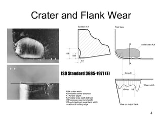
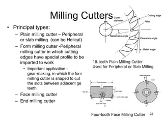
1. This document discusses cutting tool technology, including tool life factors like tool materials and geometry. It describes how tool life is affected by failure modes and wear patterns.
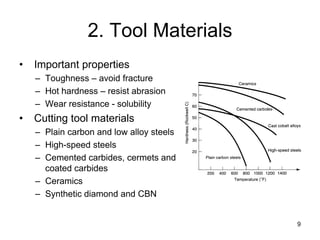
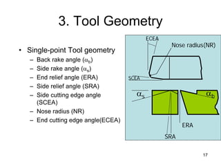
2. Different tool materials are discussed, including high-speed steel, cemented carbides, ceramics, and coatings. Tool geometry parameters that impact tool life are also covered.
3. Cutting fluids are explained as helping reduce heat and friction to improve tool life. Different fluid types and application methods are summarized.
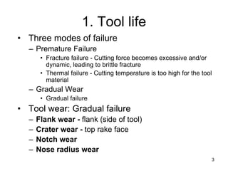


![7
Taylor’s Equation
• F. W. Taylor [1900]’s Equation
• Generalized Taylor’s Equation
– where v = cutting speed; T = tool life; and n and C depend on
feed, depth of cut, work material and, tooling material
• n is the slope of the plot
• C is the intercept on the speed axis
C
vT n
=
C
d
f
vT p
m
n
=
Tool material n C (m/min) C (ft/min)
High speed steel:
Non-steel work 0.125 120 350
Steel work 0.125 70 200
Cemented carbide
Non-steel work 0.25 900 2700
Steel work 0.25 500 1500
Ceramic
Steel work 0.6 3000 10,000](https://image.slidesharecdn.com/cuttingtool-221023125243-b8fcf5cd/85/cuttingtool-pdf-7-320.jpg)


![24
Milling Cutter
From Schey [2000]](https://image.slidesharecdn.com/cuttingtool-221023125243-b8fcf5cd/85/cuttingtool-pdf-24-320.jpg)