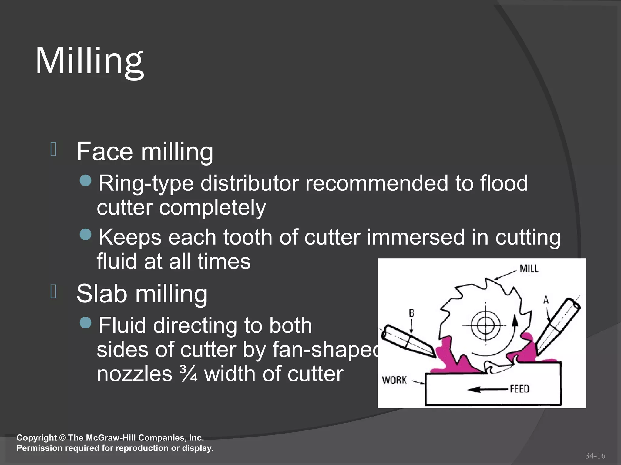
This document discusses cutting tools and machining processes. It defines cutting tool components like rake and clearance angles and describes different cutting tool materials. It explains how cutting tool angles and clearances work and affect tool life. Finally, it discusses turning and milling operations and how cutting fluids are used to cool and lubricate cutting tools during these processes.
This document discusses different types of cutting tool materials. It begins by introducing the importance of selecting the right material for the application. High carbon steel and high-speed steel were early materials but have limitations. Modern materials include cemented tungsten carbide, ceramics, and coatings. Each material has different properties like hardness, toughness, wear resistance, and temperature performance that make it suitable for specific cutting applications. Selecting the optimal material involves balancing quality, cost and tool life.
The document discusses different types of tool bits used for machining, including their properties and applications. It describes how the shape and angles of tool bits are determined by factors like the operation, material, machine power, and desired finish. Various materials for tool bits are also outlined, such as high speed steel, carbides, and diamond, each suited for different machining conditions due to their hardness, strength, and temperature resistance. Tool holders are used to securely hold the bits at an angle to facilitate chip removal during cutting.
The document discusses cutting tools and their properties. It describes different types of cutting tool materials like high-speed steel, cemented carbides, ceramics, and diamond. It explains cutting tool nomenclature and defines terms like rake angle, clearance angle, nose, and flank. It also discusses factors that affect tool life like cutting conditions, work material properties, and tool material.
Importance of cutting tools in machining industriesBipico Industries
A machine tool or metal cutting tool is used to manufacture metal components of machines through machining, a process whereby metal is selectively removed to create a desired shape. Ranging from simple to complex pieces, metal cutting tools can produce parts of different shapes and sizes. Metal Cutting Tools have gradually evolved over the past years. Today, machine tools are used on computerized numerical control (CNC) machines, which can repeat sequences with high levels of precision and produce complex pieces of various sizes and shapes. Various techniques can be used to remove unwanted metal during the process of fabricating or shaping parts, namely single edge cutting tools; multiple edge cutting tools, electrical discharge machining and grinding (abrasive cutting).
In this report the basic design principles and the current state-of-the-art for cutting tools specially designed to be applied on difficult-to-cut materials are described. One by one, the main aspects involved in tool design and construction will be explained in depth over the following sections, completing a general view of the tool world, to provide easy comprehension of the whole book. Materials for the substrates, coatings, and geometry are explained, with special attention to recent developments. A section is devoted to new machining techniques such as high-feed and plunge milling, turn milling and trochoidal milling.
The document discusses cutting tools used in machining processes. It defines single point and multi-point cutting tools. Key terms related to cutting tool geometry are defined, including relief angle, rake angle, nose radius, and their purposes. Common cutting tool materials like high-speed steel and cemented carbides are also mentioned. The document provides information on selecting cutting tool geometry and materials based on factors like the workpiece material and type of machining operation.
The document discusses different types of cutting tools and their applications. It describes various tools including alligator shears for cutting metal stock, abrasive saws for cutting hard materials, bandsaws that use continuous metal blades for uniform cutting, diamond saws used to cut stone and other hard materials in construction, hacksaws for cutting metal and plastic, high speed steel used to make cutting tools, jigsaws for cutting custom shapes, milling cutters for removing material in machining, bimetal bandsaws for cutting various metals, and tungsten carbide tipped saw blades for industrial cutting of metals, wood and plastic. It concludes by providing contact information for Littlehampton Cutting Tools Ltd.
Single point cutting tools have a single cutting edge used to remove material from a workpiece. They are used in lathe and shaper machines for operations like turning, facing, and boring. The tool has a shank, rake surface, flank surface, and a single cutting edge where the rake and flank surfaces intersect. Rake angle, which indicates the orientation of the rake surface, can be positive, negative, or zero, and influences factors like required cutting force, tool life, and machinability.
This document discusses the theory and mechanics of metal cutting. It begins by defining metal cutting as removing unwanted material from a workpiece through cutting, abrasion, or non-traditional processes. It then covers the basics of orthogonal and oblique metal cutting, tool geometry including rake and relief angles, and different types of chips that can form. The document also discusses important considerations for metal cutting like cutting speed, feed rate, depth of cut, and tool materials commonly used including high-speed steel, cemented carbides, and ceramics.
This document discusses machine tools and machining processes. It covers topics such as cutting tools, tool selection factors, tool design and terminology, forces in metal cutting, tool life, cutting speeds and feeds, tool failure modes, machinability, cutting inserts, and cutting fluids. The document is presented by Vikrant Sharma of the Mechanical Engineering department and contains diagrams to illustrate machining concepts.
The document summarizes key aspects of cutting tool technology. It discusses the three main modes of tool failure and how gradual wear is preferred. Tool materials are described, including high speed steel, cemented carbides, cermets, ceramics, and coatings. Tool geometry, including elements for single-point and multi-point tools, is covered. Functions of cutting fluids in reducing heat and friction are explained.
This document discusses cutting tool materials and their properties. It covers various tool materials including carbon steels, high-speed steel, cemented carbides, ceramics, and diamond. Cemented carbides are the most commonly used and contain tungsten carbide and a cobalt binder. The document provides details on selecting cutting tool materials based on the application, and guidelines for cutting tool design including tool angles and operating conditions.
1. Chips are formed during machining when excess metal is sheared off the workpiece. There are three main types of chips: discontinuous, continuous, and continuous with built-up edge.
2. Discontinuous chips form with brittle materials while continuous chips form with ductile materials at high speeds. Continuous chips with built-up edge form with friction at low-medium speeds.
3. Chip breakers are used to break long continuous chips for safety and chip disposal. Built-up edges form from friction but can be prevented by reducing friction, pressure, temperature through rake angle, lubrication and speed/feed adjustments.
This document provides an overview of metal cutting theory and processes. It discusses orthogonal and oblique cutting, types of cutting tools including single point and multipoint tools, tool geometry and signatures. It also covers mechanics of metal cutting including shear angle and chip formation, tool materials, tool wear and tool life, factors affecting machining, and types of metal cutting processes and chips. Cutting fluid types and applications are also summarized.
This document discusses single point cutting tools. It describes the types of tools, tool geometry including angles and designations. It explains the effects that varying the back rake angle, side rake angle, relief angle, cutting edge angle, and nose radius have on machining. Finally, it lists common tool materials and provides brief conclusions and references.
Searching for metal cutting blades, Bipico is one of the leading metal cutting tools supplier & manufacturer. We provide various metal cutting tools like hacksaw, bimetal bandsaw blades, reciprocating saw blades, abrasive cutting & grinding discs and other metal cutting saw across the globe. Visit our site www.bipico.com now for more details.
1) The document discusses metal cutting processes and machine tools. It describes different types of machining operations like turning, milling, drilling etc.
2) It explains concepts like shear angle, cutting forces, tool geometry specifications and factors affecting chip formation. Diagrams of tool geometry and forces on cutting tool are provided.
3) Equations to calculate shear angle, cutting forces and power are derived based on Merchant's metal cutting theory which involves minimum energy principle and assumes work material behaves plastically.
The sheet metal shop works with thin metal sheets to cut, form, and join them into various shapes using hand tools and simple machines. Common materials used include black iron, galvanized iron, stainless steel, copper, aluminum, tin plates, and lead. Key sheet metal hand tools include various measuring tools, hammers, snips, stakes, and groovers. Common sheet metal operations are shearing, bending, drawing, and squeezing. Important sheet metal joints include hems, seams, and specialized seams like lap, grooved, and dovetail seams. Larger machines like shearing machines, bar folders, and forming machines are also used.
The document discusses various topics related to machining processes and metal cutting:
1) It describes different types of machining processes including conventional machining methods like milling and drilling as well as non-conventional methods like EDM and laser machining.
2) The mechanics of metal cutting are explained, involving the shearing of metal layers by the tool to form chips. Factors that influence chip formation like work material properties and tool geometry are also covered.
3) Tool geometry parameters for single point cutting tools are defined according to the ASA and orthogonal rake systems, including rake angle, relief angle, and cutting edge angles.
Metal cutting involves removing unwanted material from a workpiece. In orthogonal cutting, the cutting tool edge is perpendicular to the direction of motion, so chip flow is perpendicular to the cutting edge. In oblique cutting, the cutting tool edge is at an angle to the direction of motion, so chip flow is sideways. Orthogonal cutting results in higher heat concentration, shorter tool life, and poorer surface finish than oblique cutting. Oblique cutting is used for most industrial processes like drilling and milling.
This document provides an overview of sheet metal forming processes. It discusses that sheet metal forming is used to produce parts with versatile shapes and is lightweight. Common materials used are low-carbon steel, aluminum, and titanium. The main forming processes discussed are shearing, punching, bending, deep drawing, and stamping. It covers the characteristics of sheet metal that influence formability like elongation, anisotropy, and springback. Forming parameters that affect processes like deep drawing are also summarized such as blankholder pressure, draw ratio, and clearance.
The document discusses metal cutting processes and lathe machines. It begins by defining metal cutting as the process of removing unwanted material from a block of metal in the form of chips using relative motion between the tool and workpiece. It then classifies metal cutting into orthogonal and oblique cutting. Finally, it discusses the various parts and operations of a lathe machine, including the headstock, carriage, tooling, workholding devices, and taper turning methods.
1. The document discusses the theory of metal cutting, including the chip formation process, types of chips, tool angles, tool wear mechanisms, tool materials, and cutting fluids.
2. Key aspects covered include the orthogonal cutting model, factors that influence chip type like tool angles and speeds/feeds, how tool angles impact forces and tool life, and common tool materials like HSS and cemented carbides and their characteristics.
3. Cutting fluids are discussed as being important to reduce heat at the tool-work interface and lubricate the process to increase tool life and improve surface finish. Their properties and common types used are also summarized.
This document discusses tool wear, tool life, and machinability. It defines tool life as the useful cutting time before tool failure or need for resharpening. Tool wear is caused by various mechanisms like abrasion, diffusion, and plastic deformation, and is measured by flank and crater wear. Machinability is determined by factors like surface finish, tool life, cutting forces, and chip control. The machinability of different materials depends on their properties and varies significantly. Cutting fluids are used to decrease power needs, increase heat dissipation, and improve other machinability factors.
This document discusses the design of single point cutting tools. It covers the types of tools, tool geometry, tool designation systems, and the effects of various tool angles and geometry on machining. The types of tools covered are single point and multi-point cutting tools. Tool geometry and material both play important roles in tool performance. Systems for designating tools include the ASA and ORS systems. Factors like back rake angle, side rake angle, relief angle, cutting edge angle, and nose radius influence machining forces and tool life. A variety of tool materials are also discussed.
MANUFACTURING PROCESS -1(cutting tool nomenclature)Parthivpal17
In this presentation you will learn about the CUTTING TOOL NOMENCLATURE.i.e, cutting tool materials, toolbits, factor affecting tools, characteristics of cutting tools.
This document discusses the theory of metal cutting. It covers topics such as orthogonal and oblique cutting, types of cutting tools including single-point and multipoint tools, tool geometry including rake angles and relief angles, mechanics of metal cutting including shear angle and chip formation, types of chips, tool wear and tool life, cutting fluids, and various metal cutting processes. Key points covered include shear angle significance in metal cutting, factors affecting metal cutting, and nomenclature used for describing single-point cutting tool geometry.
This document contains the answer key for a unit test on Manufacturing Technology-II. It discusses various topics related to cutting tools and machining processes, including:
1. Types of cutting tools such as single point and multipoint tools.
2. Factors that affect tool life such as rake angle, tool wear, and cutting fluids.
3. Different types of chips produced during machining such as continuous, discontinuous, and chips with built-up edge.
4. Tool materials used for different temperature ranges such as carbon steel, high-speed steel, cemented carbides, and ceramics.
5. Merchant's circle diagram which models the forces during chip formation.
This document provides an overview of cutting tools and cutting fluids. It begins by defining the objectives of understanding cutting tool nomenclature, materials, and applications. It then describes different types of cutting tools, such as high-speed steel, cemented carbides, ceramics, and diamond toolbits. It also discusses cutting fluid types like oils, emulsifiable oils, and chemical fluids, and their functions in cooling, lubricating, and prolonging tool life during machining operations.
The document discusses the theory of metal cutting, including the process of chip formation and different types of chips. It describes orthogonal and oblique cutting, factors that influence the cutting process, and chip formation mechanisms. It also covers cutting tool materials like high-speed steel, cemented carbides, ceramics, and coatings. Tool geometries such as rake angle, nose radius, and flank are defined. Different tool bit angles and tool signatures are also introduced.
Mechanics of chip formation, single point cutting tool, forces in machining, Types of chip, cutting
tools– nomenclature, orthogonal metal cutting, thermal aspects, cutting tool materials, tool wear,
tool life, surface finish, cutting fluids and Machinability
The document discusses material removal processes and metal cutting. It describes the nature of relative motion between the tool and workpiece in different operations like turning, boring, drilling, etc. It discusses factors that influence the cutting process like cutting speed, depth of cut, and tool angles. It explains the mechanics of chip formation through shear plane theory and describes different types of chips like continuous, discontinuous, and those with built-up edges. It also discusses tool wear patterns like flank and crater wear.
The document discusses milling processes and provides details about various milling techniques. It defines milling, describes up and down milling methods, and covers topics such as milling machines, cutters, operations, and factors that influence tool life. Examples of peripheral and face milling are illustrated.
Possible Interview Questions/Contents From Manufacturing Technology IIDr. Ramesh B
1. Machining is a process that removes material from a workpiece through cutting or other shear mechanisms in order to change its shape or size. The three fundamental machining parameters are cutting speed, depth of cut, and feed.
2. Material removal rate is the volume of material removed per minute during machining operations like turning, where it is calculated as MRR=Vfd. Chip formation affects surface finish, cutting forces, temperature, tool life, and tolerances.
3. Tool wear occurs due to interactions between the tool and chip like adhesion and abrasion, leading to flank wear, crater wear, chipping, and breakage. Tool wear degrades surface finish and increases tolerances and machining
Mechanics of Chip Formation - Unit of MFThodmech61
The document discusses material removal processes and machining. It covers various machining operations like turning, drilling, boring, and milling. It describes the fundamental process of orthogonal cutting and factors that influence the cutting process like cutting speed, depth of cut, feed, cutting fluids, tool angles, chip types, and tool wear. Continuous chips result in good surface finish and tool life while discontinuous chips are easier to dispose but can cause vibration. Proper selection of factors like material, cutting speed, and rake angle can produce different chip types.
This chapter aims to provide basic backgrounds of different types of machining processes and highlights on an understanding of important parameters which affects machining of metals with their chip removals.
Metal cutting or Machining is the process of producing workpiece by removing unwanted material from a block of metal. in the form of chips. This process is most important since almost all the products get their final shape and size by metal removal. either directly or indirectly.
The major drawback of the process is loss of material in the form of chips. In this chapter. we shall have a fundamental understanding of the basic metal process.
The document discusses tool specification and chip formation mechanisms. It begins by outlining the American System for specifying tool angles such as rake, relief, and cutting edge angles. It then explains how each angle impacts cutting forces and tool strength. The document also describes the mechanics of chip formation, defining shear angle and relating it to tool rake angle. It outlines factors that influence chip type and discusses tool surfaces and reference planes. Finally, it covers tool wear mechanisms, tool life definitions, and factors that tool life depends on such as cutting speed, depth of cut, and feed rate.
The document discusses various topics related to machining processes including:
- The objectives of understanding machining processes and estimating machining time and costs.
- The mechanics of chip formation during metal cutting using single-point cutting tools.
- Factors that influence tool life such as cutting speed, feed rate, depth of cut, tool geometry, and work material.
- Different types of chips produced during machining such as continuous, discontinuous, and chips with a built-up edge.
- Properties required for cutting tool materials including hardness, wear resistance, toughness, thermal conductivity and elements commonly used.
- Common cutting tool materials including high-carbon steel, high-speed steel, cemented carbides
The document provides an overview of the theory of metal cutting. It discusses the mechanics of chip formation, types of chips, cutting tools and their components/angles. It also describes the metal cutting process, orthogonal vs oblique cutting, thermal aspects of cutting, tool wear and life, factors affecting surface finish and machinability. Cutting fluids, their functions and types are also summarized.
The document discusses metal cutting and machining processes. It defines material removal processes as shaping operations that remove material from a work part to achieve a desired geometry. The two main types are machining, using a sharp cutting tool, and abrasive processes, using abrasive particles. Machining is important because it can cut a variety of materials and produce complex part shapes and features like threads and holes. However, it wastes material in chips and can be time consuming. The document then discusses chip formation mechanisms and types of chips produced from different materials and cutting conditions. It also defines tool elements, angles, and different types of single-point and multi-point cutting tools.
1. The document discusses the theory of metal cutting, including mechanics of chip formation, types of chips, cutting tool materials, tool wear, and other related topics.
2. It describes the different types of tool wear that can occur, including flank wear which results from the gradual wearing away of the cutting edge, and crater wear.
3. The key factors that influence chip formation and tool wear are also examined, such as material properties, cutting conditions, tool geometry, and choice of cutting tool material.
This document provides information on various metal cutting processes and fundamentals of cutting. It begins with acknowledging photographs from a textbook on the subject. It then discusses the nature of relative motion between the tool and workpiece for different operations like turning, boring, drilling, etc. It covers topics like types of cutting, factors influencing the cutting process, types of chips, chip breakers, tool nomenclature, forces in cutting, temperature distribution, tool wear, mechanics of chip formation, and surfaces produced by cutting. It also provides three example problems calculating cutting speed and material removal rate for turning, milling and drilling operations.
1. Objectives
Use the nomenclature of a cutting-tool point
Explain the purpose of each type of rake and
clearance angle
Identify the applications of various types of
cutting-tool materials
Describe the cutting action of different types of
machines
29-1
2. 29-2
Cutting Tools
One of most important components in
machining process
Performance will determine efficiency of
operation
Two basic types (excluding abrasives)
Single point and multi point
Must have rake and clearance angles
ground or formed on them
3. Cutting-Tool Materials
Lathe toolbits generally made of five
materials
High-speed steel
Cast alloys (such as stellite)
Cemented carbides
Ceramics
Cermets
More exotic finding wide use
Borazon and polycrystalline diamond
29-3
4. Diamond Toolbits
Used mainly to machine nonferrous metals
and abrasive nonmetallics
Single-crystal natural diamonds
High-wear but low shock-resistant factors
Polycrystalline diamonds
Tiny manufactured diamonds fused together
and bonded to suitable carbide substrate
29-4
6. Cutting-Tool Nomenclature
Nose radius: radius to which nose is ground
Size of radius will affect finish
○ Rough turning: small nose radius (.015in)
○ Finish cuts: larger radius (.060 to .125 in.)
Point: end of tool that has been ground for
cutting purposes
29-6
10. Factors Affecting the Life of a
Cutting Tool
Type of material being cut
Microstructure of material
Hardness of material
Type of surface on metal (smooth or scaly)
Material of cutting tool
Profile of cutting tool
Type of machining operation being performed
Speed, feed, and depth of cut
29-10
14. Characteristics of a Good Cutting
Fluid
1. Good cooling 6. Rust
capacity resistance
2. Good lubricating 7. Nontoxic
qualities
8. Transparent
3. Resistance to
rancidity 9. Nonflammable
4. Relatively low
viscosity
5. Stability (long life)
34-14
15. Functions of a Cutting Fluid
Prime functions
Provide cooling
Provide lubrication
Other functions
Prolong cutting-tool life
Provide rust control
Resist rancidity
34-15
The side cutting edge angle is the angle the cutting edge forms with the side of the tool shank (Fig. 29-4). Side cutting angles for a general-purpose lathe cutting tool may vary from 10° to 20°, depending on the material cut. If this angle is too large (over 30°), the tool will tend to chatter. The end cutting edge angle is the angle formed by the end cutting edge and a line at right angles to the centerline of the toolbit (Fig. 29-4). This angle may vary from 5° to 30°, depending on the type of cut and finish desired. An angle of 5° to 15° is satisfactory for roughing cuts; angles between 15° and 30° are used for general-purpose turning tools. The larger angle permits the cutting tool to be swiveled to the left for taking light cuts close to the dog or chuck, or when turning to a shoulder. The side relief (clearance) angle is the angle ground on the flank of the tool below the cutting edge (Figs. 29-4 and 29-5). This angle is generally 6° to 10°. The side clearance on a toolbit permits the cutting tool to advance lengthwise into the rotating work and prevents the flank from rubbing against the workpiece. The end relief (clearance) angle is the angle ground below the nose of the toolbit, which permits the cutting tool to be fed into the work. It is generally 10° to 15° for general-purpose tools (Figs. 29-4 and 29-5). This angle must be measured when the toolbit is held in the toolholder. The end relief angle varies with the hardness and type of material and the type of cut. The end relief angle is smaller for harder materials, providing support under the cutting edge. The side rake angle is the angle at which the face is ground away from the cutting edge. For general-purpose toolbits, the side rake is generally 14° (Figs. 29-4 and 29-5). Side rake creates a keener cutting edge and allows the chips to flow away quickly. For softer materials, the side rake angle is generally increased. Side rake may be either positive or negative, depending on the material being cut. The angle of keennes s is the included angle produced by grinding side rake and side clearance on a toolbit (Fig. 29-4). This angle may be altered, depending on the type of material machined, and will be greater (closer to 90°) for harder materials. The back (top) rake angle is the backward slope of the tool face away from the nose. The back rake angle is generally about 20° and is provided for in the toolholder (Fig. 29-5). Back rake permits the chips to flow away from the point of the cutting tool. Two types of back or top rake angles are provided on cutting tools and are always found on the top of the toolbit: > Positive rake (Fig. 29-6a), where the point of the cutting tool and the cutting edge contact metal first and the chip moves down the face of the toolbit > Negative rake (Fig. 29-6b), where the face of the cutting tool contacts the metal first and the chip is forced up the face of the toolbit