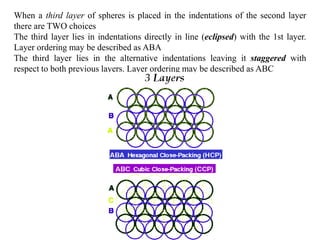
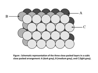
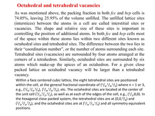
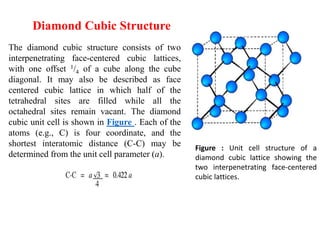
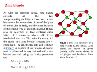
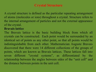
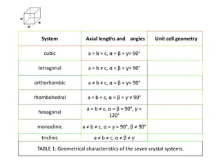
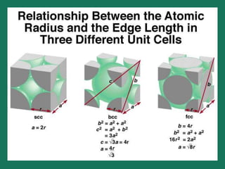
The document explains crystal structures, focusing on the arrangement of atoms in crystals through concepts such as Bravais lattices, unit cells, and Miller indices. It describes the seven crystal systems, close-packed structures, and specific configurations like diamond cubic, zinc blende, and rock salt. Additionally, it discusses the geometric characteristics of unit cells and methods to define crystal orientations and atomic arrangements within these structures.


![Miller Indices (hkl)
Miller indices are a notation system in crystallography for planes
and directions in crystal (Bravais) lattices.
The orientation of a surface or a crystal plane may be defined by
considering how the plane (or indeed any parallel plane) intersects
the main crystallographic axes of the solid. The application of a set
of rules leads to the assignment of the Miller Indices , (hkl) ; A set
of numbers which quantify the intercepts and thus may be used to
uniquely identify the plane or surface.
The designation of the individual vectors within any given crystal
lattice is indicated by the notation [hkl], where h, k, and l are
reciprocals of the point at which the vector exits the unit cell. The
origination of all vectors is assumed defined as [000]. For example,
the direction along the a-axis according to this scheme would be
[100] because this has a component only in the a-direction and no
component along either the b or c axial direction.](https://image.slidesharecdn.com/unit1-200924093643/85/Crystal-Structure-14-320.jpg)
![Miller Indices are a symbolic vector representation for the orientation of an
atomic plane in a crystal lattice and are defined as the reciprocals of the
fractional intercepts which the plane makes with the crystallographic axes.
A vector diagonally along the face defined by the a and b axis would be
[110], while going from one corner of the unit cell to the opposite
corner would be in the [111] direction.
Figure 2 shows some examples of the various directions in the unit cell.
The crystal direction notation is made up of the lowest combination of
integers and represents unit distances rather than actual distances. A
[222] direction is identical to a [111], so [111] is used. Fractions are not
used. For example, a vector that intercepts the center of the top face of
the unit cell has the coordinates x = 1/2, y = 1/2, z = 1. All have to be
inversed to convert to the lowest combination of integers (whole
numbers); i.e., [221] in Figure 2. Finally, all parallel vectors have the
same crystal direction, e.g., the four vertical edges of the cell shown
in Figure 2 all have the crystal direction [hkl] = [001].](https://image.slidesharecdn.com/unit1-200924093643/85/Crystal-Structure-15-320.jpg)

![Crystal directions may be grouped in families. To avoid confusion
there exists a convention in the choice of brackets surrounding the
three numbers to differentiate a crystal direction from a family of
direction. For a direction, square brackets [hkl] are used to
indicate an individual direction. Angle brackets <hkl> indicate a
family of directions. A family of directions includes any directions
that are equivalent in length and types of atoms encountered. For
example, in a cubic lattice, the [100], [010], and [001] directions
all belong to the <100> family of planes because they are
equivalent. If the cubic lattice were rotated 90°, the a, b,
and c directions would remain indistinguishable, and there would
be no way of telling on which crystallographic positions the atoms
are situated, so the family of directions is the same. In a hexagonal
crystal, however, this is not the case, so the [100] and [010] would
both be <100> directions, but the [001] direction would be
distinct. Finally, negative directions are identified with a bar over
the negative number instead of a minus sign.](https://image.slidesharecdn.com/unit1-200924093643/85/Crystal-Structure-17-320.jpg)

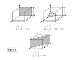
![Planes in a crystal can be specified using a notation called Miller
indices. The Miller index is indicated by the notation [hkl]
where h, k, and l are reciprocals of the plane with the x, y,
and z axes. To obtain the Miller indices of a given plane requires
the following steps:
Step 1. The plane in question is placed on a unit cell.
Step 2. Its intercepts with each of the crystal axes are then
found.
Step 3. The reciprocal of the intercepts are taken.
Step 4. These are multiplied by a scalar to insure that is in the
simple ratio of whole numbers.
For example, the face of a lattice that does not intersect the y or z
axis would be (100), while a plane along the body diagonal would
be the (111) plane. An illustration of this along with the (111) and
(110) planes is given in Figure 3.
Crystal Planes & Miller Indices](https://image.slidesharecdn.com/unit1-200924093643/85/Crystal-Structure-19-320.jpg)