Space lattice, Unit cell, Bravais lattices (3-D), Miller indices, Lattice planes, Hexagonal closed packing (hcp) structure, Characteristics of an hcp cell, Imperfections in crystal: Point defects (Concentration of Frenkel and Schottky defects).
X – ray diffraction : Bragg’s law and Bragg’s spectrometer, Powder method, Rotating crystal method.
Crystal Material, Non-Crystalline Material, Crystal Structure, Space Lattice, Unit Cell, Crystal Systems, and Bravais Lattices, Simple Cubic Lattice, Body-Centered Cubic Structure, Face centered cubic structure, No of Atoms per Unit Cell, Atomic Radius, Atomic Packing Factor, Coordination Number, Crystal Defects, Point Defects, Line Defects, Planar Defects, Volume Defects.
Crystal Material, Non-Crystalline Material, Crystal Structure, Space Lattice, Unit Cell, Crystal Systems, and Bravais Lattices, Simple Cubic Lattice, Body-Centered Cubic Structure, Face centered cubic structure, No of Atoms per Unit Cell, Atomic Radius, Atomic Packing Factor, Coordination Number, Crystal Defects, Point Defects, Line Defects, Planar Defects, Volume Defects.
NANO106 is UCSD Department of NanoEngineering's core course on crystallography of materials taught by Prof Shyue Ping Ong. For more information, visit the course wiki at http://nano106.wikispaces.com.
Metallurgy is a domain of materials science and engineering that studies the physical and chemical behavior of metallic elements, their inter-metallic compounds, and their mixtures, which are called alloys.
Metallurgy can also be described as the technology of metals, the way in which science is applied to the production of metals and the engineering of metal .
This article is about the 2016 decision to demonetise 500- and 1000-rupee banknotes. It is not to be confused with The High Denomination Bank Notes (Demonetisation) Act, 1978.
As a practicing member of Virginia Vein Care, Lawrence J. Markovitz, MD, treats a variety of vein diseases. Dr. Lawrence Markovitz comes to this role with an in-depth knowledge of human veins, how they work, and what helps to maintain their health.
Entrevista a Nelson Portugal sobre liderazgo. ¿qué es para ti ser un líder? ¿Te consideras un líder? ¿En qué momento lo has sido? ¿Hay alguna clave para nosotros poder ser líderes o desarrollar el liderazgo? Son algunas de las preguntas que responderá en esta entrevista.
Web Oficial Nelson Portugal (http://www.nelsonportugal.com)
Crystallography is the experimental science of determining the arrangement of atoms in crystalline solids. Crystallography is a fundamental subject in the fields of materials science and solid-state physics (condensed matter physics). The word crystallography is derived from the Ancient Greek word κρύσταλλος (krústallos; "clear ice, rock-crystal"), with its meaning extending to all solids with some degree of transparency, and γράφειν (gráphein; "to write"). In July 2012, the United Nations recognised the importance of the science of crystallography by proclaiming that 2014 would be the International Year of Crystallography.
Crystallography and X-ray diffraction (XRD) Likhith KLIKHITHK1
Atoms in materials are arranged into crystal structures and microstructures.
Periodic arrangement of atoms depends strongly on external factors such as temperature, pressure, and cooling rate during solidification. Solid elements and their compounds are classified into amorphous, polycrystalline, and single crystalline materials. The amorphous solid materials are isotropic in nature because their atomic arrangements are not regular and possess the same properties in all directions. In contrast, the crystalline materials are anisotropic because their atoms are arranged in regular and repeated pattern, and their properties vary with direction. The polycrystalline materials are combinations of several crystals of varying shapes and sizes. The properties of polycrystalline materials are strongly dependent on distribution of crystals sizes, shapes, and orientations within the individual crystal. Diffraction pattern or intensities of X-ray diffraction techniques are used for characterizing and probing arrangement of atoms in each unit cell, position of atoms, and atomic spacing angles because of comparative wavelength of X-ray to atomic size.The X-ray diffraction, which is a non-destructive technique, has wide range of material analysis including minerals, metals, polymers, ceramics, plastics, semiconductors, and solar cells. The technique also has wide industry application including aerospace, power generation, microelectronics, and several others. The X-ray crystallography remained a complex field of study despite wide industrial applications.
Hierarchical Digital Twin of a Naval Power SystemKerry Sado
A hierarchical digital twin of a Naval DC power system has been developed and experimentally verified. Similar to other state-of-the-art digital twins, this technology creates a digital replica of the physical system executed in real-time or faster, which can modify hardware controls. However, its advantage stems from distributing computational efforts by utilizing a hierarchical structure composed of lower-level digital twin blocks and a higher-level system digital twin. Each digital twin block is associated with a physical subsystem of the hardware and communicates with a singular system digital twin, which creates a system-level response. By extracting information from each level of the hierarchy, power system controls of the hardware were reconfigured autonomously. This hierarchical digital twin development offers several advantages over other digital twins, particularly in the field of naval power systems. The hierarchical structure allows for greater computational efficiency and scalability while the ability to autonomously reconfigure hardware controls offers increased flexibility and responsiveness. The hierarchical decomposition and models utilized were well aligned with the physical twin, as indicated by the maximum deviations between the developed digital twin hierarchy and the hardware.
Student information management system project report ii.pdfKamal Acharya
Our project explains about the student management. This project mainly explains the various actions related to student details. This project shows some ease in adding, editing and deleting the student details. It also provides a less time consuming process for viewing, adding, editing and deleting the marks of the students.
NO1 Uk best vashikaran specialist in delhi vashikaran baba near me online vas...Amil Baba Dawood bangali
Contact with Dawood Bhai Just call on +92322-6382012 and we'll help you. We'll solve all your problems within 12 to 24 hours and with 101% guarantee and with astrology systematic. If you want to take any personal or professional advice then also you can call us on +92322-6382012 , ONLINE LOVE PROBLEM & Other all types of Daily Life Problem's.Then CALL or WHATSAPP us on +92322-6382012 and Get all these problems solutions here by Amil Baba DAWOOD BANGALI
#vashikaranspecialist #astrologer #palmistry #amliyaat #taweez #manpasandshadi #horoscope #spiritual #lovelife #lovespell #marriagespell#aamilbabainpakistan #amilbabainkarachi #powerfullblackmagicspell #kalajadumantarspecialist #realamilbaba #AmilbabainPakistan #astrologerincanada #astrologerindubai #lovespellsmaster #kalajaduspecialist #lovespellsthatwork #aamilbabainlahore#blackmagicformarriage #aamilbaba #kalajadu #kalailam #taweez #wazifaexpert #jadumantar #vashikaranspecialist #astrologer #palmistry #amliyaat #taweez #manpasandshadi #horoscope #spiritual #lovelife #lovespell #marriagespell#aamilbabainpakistan #amilbabainkarachi #powerfullblackmagicspell #kalajadumantarspecialist #realamilbaba #AmilbabainPakistan #astrologerincanada #astrologerindubai #lovespellsmaster #kalajaduspecialist #lovespellsthatwork #aamilbabainlahore #blackmagicforlove #blackmagicformarriage #aamilbaba #kalajadu #kalailam #taweez #wazifaexpert #jadumantar #vashikaranspecialist #astrologer #palmistry #amliyaat #taweez #manpasandshadi #horoscope #spiritual #lovelife #lovespell #marriagespell#aamilbabainpakistan #amilbabainkarachi #powerfullblackmagicspell #kalajadumantarspecialist #realamilbaba #AmilbabainPakistan #astrologerincanada #astrologerindubai #lovespellsmaster #kalajaduspecialist #lovespellsthatwork #aamilbabainlahore #Amilbabainuk #amilbabainspain #amilbabaindubai #Amilbabainnorway #amilbabainkrachi #amilbabainlahore #amilbabaingujranwalan #amilbabainislamabad
CFD Simulation of By-pass Flow in a HRSG module by R&R Consult.pptxR&R Consult
CFD analysis is incredibly effective at solving mysteries and improving the performance of complex systems!
Here's a great example: At a large natural gas-fired power plant, where they use waste heat to generate steam and energy, they were puzzled that their boiler wasn't producing as much steam as expected.
R&R and Tetra Engineering Group Inc. were asked to solve the issue with reduced steam production.
An inspection had shown that a significant amount of hot flue gas was bypassing the boiler tubes, where the heat was supposed to be transferred.
R&R Consult conducted a CFD analysis, which revealed that 6.3% of the flue gas was bypassing the boiler tubes without transferring heat. The analysis also showed that the flue gas was instead being directed along the sides of the boiler and between the modules that were supposed to capture the heat. This was the cause of the reduced performance.
Based on our results, Tetra Engineering installed covering plates to reduce the bypass flow. This improved the boiler's performance and increased electricity production.
It is always satisfying when we can help solve complex challenges like this. Do your systems also need a check-up or optimization? Give us a call!
Work done in cooperation with James Malloy and David Moelling from Tetra Engineering.
More examples of our work https://www.r-r-consult.dk/en/cases-en/
Saudi Arabia stands as a titan in the global energy landscape, renowned for its abundant oil and gas resources. It's the largest exporter of petroleum and holds some of the world's most significant reserves. Let's delve into the top 10 oil and gas projects shaping Saudi Arabia's energy future in 2024.
Industrial Training at Shahjalal Fertilizer Company Limited (SFCL)MdTanvirMahtab2
This presentation is about the working procedure of Shahjalal Fertilizer Company Limited (SFCL). A Govt. owned Company of Bangladesh Chemical Industries Corporation under Ministry of Industries.
Explore the innovative world of trenchless pipe repair with our comprehensive guide, "The Benefits and Techniques of Trenchless Pipe Repair." This document delves into the modern methods of repairing underground pipes without the need for extensive excavation, highlighting the numerous advantages and the latest techniques used in the industry.
Learn about the cost savings, reduced environmental impact, and minimal disruption associated with trenchless technology. Discover detailed explanations of popular techniques such as pipe bursting, cured-in-place pipe (CIPP) lining, and directional drilling. Understand how these methods can be applied to various types of infrastructure, from residential plumbing to large-scale municipal systems.
Ideal for homeowners, contractors, engineers, and anyone interested in modern plumbing solutions, this guide provides valuable insights into why trenchless pipe repair is becoming the preferred choice for pipe rehabilitation. Stay informed about the latest advancements and best practices in the field.
Overview of the fundamental roles in Hydropower generation and the components involved in wider Electrical Engineering.
This paper presents the design and construction of hydroelectric dams from the hydrologist’s survey of the valley before construction, all aspects and involved disciplines, fluid dynamics, structural engineering, generation and mains frequency regulation to the very transmission of power through the network in the United Kingdom.
Author: Robbie Edward Sayers
Collaborators and co editors: Charlie Sims and Connor Healey.
(C) 2024 Robbie E. Sayers
Welcome to WIPAC Monthly the magazine brought to you by the LinkedIn Group Water Industry Process Automation & Control.
In this month's edition, along with this month's industry news to celebrate the 13 years since the group was created we have articles including
A case study of the used of Advanced Process Control at the Wastewater Treatment works at Lleida in Spain
A look back on an article on smart wastewater networks in order to see how the industry has measured up in the interim around the adoption of Digital Transformation in the Water Industry.
2. CONTENTS
• Crystal structure
– space lattice,
– Miller indices,
– lattice planes,
– hexagonal closed packing (hcp) structure,
– characteristics of an hcp cell.
– Imperfections in crystal: Point defects (Frenkel
and Schottky).
• X – ray diffraction
– Bragg’s law and Bragg’s spectrometer,
– powder method,
– rotating crystal method.
3. INTRODUCTION
Three States of Matter:
– Solids
– Liquids
– Gases
Solids:
The aggregates of atoms which preserve their
volumes and shapes unless subjected to large
external force are called solids”.
There are two types of solids :
Amorphous (non-crystalline) and
Crystalline
These are shown in Fig.
4.
5. Difference Between Amorphous and Crystalline Solids
Amorphous
• Amorphous solids (means
without form) are the
solids which lacks the
regular arrangement of
atoms or molecules and
hence they have a short
range order or no order in
their structure :
ABCBBACBCACCB...
• Do not have sharp melting
point (because all bonds
are not equally strong)
• Isotropic (Physical
properties are same in
different directions)
• Examples: glass, wax,
plastics, etc.
Crystalline
• A crystalline solid is the
one in which there is a
regular repeating pattern
in the structure, or in
other words, there is long-
range order :
ABCABCABCABC…
• Have sharp melting point
(because all bond are
equally strong)
• Anisotropic (Physical
properties are different
in different directions)
• Examples: diamond, table
salt, ice, methanol, sodium
chloride, etc.
6. CRYSTAL LATTICES
A lattice is an infinite, regular array of points in
space.
# In the definition it should be noticed that no mention
is made of atoms or any physical objects, just points
in space - no more, no less. Hence we treat the lattice
as a mathematical abstraction. Therefore, it is clear
that there is no lattice inside the crystal. Even if we
look the crystal through a powerful microscope we
will not be able to see the lattice points, but rather
atoms or groups of atoms. The lattice provides the
'recipe' that determines how the atomic or molecular
units are to be repeated throughout the space to
make the crystal structure.
7. Plane Lattice
Consider an array of points in such a way that the
environment about any point is identical with the
environment about any other point. Such an array of
points in two dimensions is shown in Fig. and is called a
plane lattice.
For constructing a two dimensional lattice, choose any two
convenient axis such that the points lie at equal intervals a
and b along these axis as shown in the Fig. There are
generally 5 lattices in two dimensions: Oblique, Square,
Hexagonal, Rectangular and Centered Rectangular lattice.
8. Space Lattice
If this array of points is extended to three
dimensions then the array of points is called space
lattice. For constructing the space lattice the points
are arranged at equal intervals c in the third
direction also. There are 14 space lattices in total,
called Bravais Lattice.
Thus a lattice may also be defined as a parallel net
like arrangement of points such that the
environment about any point is identical with the
environment about any other point.
9. Basis
A basis is defined as an assembly of atoms, ions or
molecules identical in composition, arrangement and
orientation.
Basis consists of the simplest arrangement of atoms
which is repeated at every point in the lattice to build up
the crystal structure.
The number of atoms in a basis may be one as in case of
many metals and inert gases, but could be as large as
1000 in many structures.
In ionic crystals, a basis is composed of two distinct
types of ions. For example, Na+
and Cl-
in a NaCl crystal.
10. When basis is attached identically to each lattice point,
the actual crystal structure is formed as shown in the
Fig.
The relation can be written as
Lattice + Basis = Crystal Structure
11. UNIT CELL
A unit cell is a region of space which when repeated
by primitive translation vectors fills all space. Thus a
unit cell is defined as the smallest geometrical figure,
the repetitions of which give the actual crystal
structure.
The choice of the unit cell is not unique. It can be
constructed in a number of ways, but the unit cell should
be chosen in such a way that it conveys all the symmetry
of a crystal lattice, by having shortest possible size,
which makes the mathematical calculations easy.
Each atom or molecule in a unit cell is considered as a
lattice point. The distance between the two atoms or ions
of the same type is the ‘length of the unit cell’.
12. Primitive and Non - primitive unit cell
A unit cell which contain just one lattice point is
called primitive unit cell. This cell is the smallest
part of the lattice which when repeated would
reconstruct the entire crystal structure. It is a
minimum volume unit cell and is denoted by the
letter p. A unit cell which contain more than one
lattice point is called non - primitive unit cell.
These two cells are shown in the Fig.
13.
14.
15. For a three dimensional case, the unit cell is a
parallelopiped formed by basic vectors a, b and c as
concurrent edges and the angles α, β and γ, between (b,
c), (c, a), and (a, b) respectively as explained in the
following Figures.
16. Thus, in general, a unit cell may be defined as the smallest
volume of a solid from which the entire crystal may be
constructed by translational repetitions in 3-dimension and which
represent fully all the characteristics of a particular crystal. In
Fig. a three dimensional unit cell is shown by the shaded portion.
18. Lattice Parameters
In a unit cell the vectors a, b and
c are called translation
vectors or primitive basis
vectors. In two dimensionsn the
area of the unit cell is (a x b)
while in three dimension the
volume of the unit cell is (a x
b).c . In Fig. the direction of
the primitive basis vectors
defines the crystallographic
axis. The angles between these
axis are called interfacial
angles, which are α, β and γ,
between (b, c), (c, a), and (a, b)
respectively. Primitive vectors
and interfacial angles together
are called lattice parameters.
19. CRYSTAL SYSTEMS AND BRAVAIS LATTICES
Crystals of different substances have similar shapes and
hence the crystals are classified into the so called crystal
systems depending upon their axial ratio and the interfacial
angles α, β and γ. In three-dimension, there are 7 crystal
systems. Bravais showed that throughout the seven crystal
systems there are fourteen unique lattice types possible.
These are known as Bravais or space lattices. These seven
crystal systems with examples are :
• Cubic(CsCl, NaCl, Cu)
• Tetragonal(SnO2)
• Orthorhombic(PbSO4, MgSO4)
• Monoclinic(FeSO4, LiSO4 ⋅ H2O)
• Triclinic(FeSO4 ⋅ 5H2O, K2Cr2O7)
• Trigonal (Rhombohedral)(Sb, As, CaCO3)
• Hexagonal(Zn, Cd, Ni, As, SiO2)
The characteristics features of these crystal systems and the
corresponding Bravais lattices are as follows:
20. No. Crystal class Intercepts
on Axes
Angles between
Axes
Bravais space lattice
1 Cubic a = b = c α = β = γ = 900 Simple, body-centred,
face-centred
2 Tetragonal a = b ≠ c α = β = γ = 900 Simple, body-centred
3 Orthorhombic a ≠ b ≠ c α = β = γ = 900 Simple, body-centred,
face-centred,
Base(side)-centred
4 Trigonal a = b = c α = β = γ ≠ 900 Simple
5 Hexagonal a = b ≠ c α = β = 900
,
γ = 1200
Simple
6 Monoclinic a ≠ b ≠ c α = γ = 900
≠ β Simple, base-centred
7 Triclinic a ≠ b ≠ c α ≠ β ≠ γ Simple
21.
22.
23. MILLER INDICES
The crystal structure may be regarded as made up of an
aggregate of a set of parallel equidistant planes passing
through at least one lattice point or a number of lattice
points. These planes are known as Lattice Planes. For a
given crystal, lattice planes can be chosen in different
ways as shown in Fig.
24. In order to designate a lattice plane, British mineralogist
William H. Miller, in 1839, developed a method by using
three numbers (h k l) which are known as Miller Indices.
Miller Indices are the three smallest possible integers,
which have the same ratio as the reciprocals of
intercepts of the plane concerned on the three axis.
# Miller indices are integer sets that were created to
distinguish directions and planes in a lattice. They are used
primarily in crystalline structures because they describe
planes in relation to a larger lattice in relative terms, as
opposed to absolute terms. An example of this is describing
planes in a building, Miller indices would distinguish the floor
from the walls, and north wall from west wall, however it
would not distinguish the 4th floor from the 5th floor. This
is useful in crystal lattices because the planes are the same
in many directions(like floors in a tall building).
25.
26. • Important points:
• Miller indices define the orientation of the plane
within the unit cell
• If a set of planes is perpendicular to any of the axes,
it would cut that axes at ∞, hence the Miller index
along that direction is 1/∞ = 0.
• If a plane to be indexed has an intercept along the
negative portion of a coordinate axis, a minus sign is
placed over the corresponding index.
• The Miller Index defines a set of planes parallel to
one another (remember the unit cell is a subset of
the “infinite” crystal), e.g., (002) planes are parallel
to (001) planes, and so on.
27. Let us take an example to find the Miller Indices of a given
plane(see Fig.):
• Intercepts: 2a 1b 1c
• Dividing by unit translation vectors:
2a/a 1b/b 1c/c = 2 1 1
• Taking the reciprocals: ½ 1/1 1/1
• Reducing to whole numbers: 1 2 2
• Miller indices: (122)
28.
29.
30.
31.
32.
33. In this example, the plane
shown (shaded) cuts the a
length (along the x-axis) at
1/2.
The same plane cuts the b
length (along y) just once at 1
and the c length (along z) at
1/2.
Thus, the Miller indices for
this set of planes would be (2
1 2).
34. Here the given plane
is perpendicular to y
and cuts at ∞, 1, ∞
Therefore the Miller
indices for this plane
will be (0 1 0)
35. For a given Miller indices, a plane can be drawn by taking
the reciprocals of the given indices on the corresponding
axes. Some of the planes and their corresponding Miller
indices are shown in following Figures.
39. INTERPLANER DISTANCE OR SPACING
Interplaner spacing is defined as the perpendicular
distance dhkl between corresponding planes. It is also
perpendicular distance from the origin to the set of parallel
planes(see Fig.)
40. • To calculate the interplaner
distance, let us take a simple
unit cell in which the coordinate
axes are orthogonal.
• Let us consider set of planes
defined by Miller indices (hkl)
with the reference plane passing
through the origin O.
• The next plane, as shown in Fig.
cuts the intercepts a/h, b/k and
c/l on x, y and z axes
respectively.
• Draw a normal ON = d to the
plane ABC.
• ‘d’ the length of the normal from
the origin is the distance
between the adjacent planes and
is the required interplaner
spacing.
41. Now, from the Fig. we have
ha
d
/
cos =α
kb
d
/
cos =β
lc
d
/
cos =γ
Using the cosine
theorem
1coscoscos 222
=++ γβα
1
///
222
=
+
+
lc
d
kb
d
ha
d
we have
2
1
2
2
2
2
2
2 −
++=
c
l
b
k
a
h
dsolving we get
For a cubic lattice, a = b = c, therefore, we get
222
lkh
a
dhkl
++
=
d100 = a, d110 = a/√2 and d111 = a/√3.
Also, For a cubic lattice,
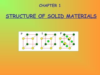
42. Physical Parameters for Crystal Structure
(i)Number of Atoms per Unit Cell
Number of atoms per unit cell determines how closely the
solid is packed and is given by
N = Nc/8 + Nf/2 + Ni
here Nc is the number of corner atoms, Nf the number of
face centred atoms and Ni the number of body centred
atoms(see Fig.).
For SC crystal : In a SC crystal, there are 8 atoms only,
each at one corner. Each atom is shared by 8 unit cells.
Therefore, we have
N = Nc/8 = 8/8 = 1
For BCC crystal :N = Nc/8 + Nf/2 + Ni = 8/8 + 0 + 1 = 2
For FCC crystal :N = Nc/8 + Nf/2 + Ni = 8/8 + 6/2 + 0 = 4
43. (ii) Coordination Number (CN)
In a crystal, the number of nearest neighbours of the
same type and at equal distances from the given atom
is called coordination number.
For SC : The corner atoms are the nearest neighbours
of each other. Here CN = 6(see Fig.) which is a group
of 8 unit cell and atom at the centre has six corner
atoms as its nearest neighbours).
44. For BCC : In this case all the corner atoms are at
equal distances from the body centered atom.
Hence CN = 8.
For FCC : Here the nearest neighbours of any
corner atom are the face centered atoms of the
surrounding unit cells. Now for any corner atom
there are 4 face centered atoms in each plane
and there are three such planes. Therefore, CN =
12.
45. (iii) Atomic Radius and Nearest Neighbour Distance (NND)
In a crystal the atoms are assumed to be spheres in contact.
Now atomic radius is defined as half the distance between
the nearest neighbours in a crystal of pure element, i.e.,
the distance between the centres of neighbouring atoms.
For SC : In a SC structure, corner atoms are the nearest
neighbours and are in touch with each other. If the side of
the unit cell is ‘a’ and ‘r’ be the radius , then
2r = a or r = a/2
Now Nearest Neighbour Distance(NND) is given by 2r
Therefore, NND = 2r = a
48. (iv) Atomic Packing Fraction (or Factor) (APF)
It is defined as the ratio of the volume of the atoms occupying the unit
cell to the volume of the unit cell. It is also called relative packing
density.
APF = Volume occupied by the atoms in a unit cell / Volume of the
unit cell.
SC Crystal : No. of atoms/unit cell = 1
Volume of one atom = 4/3 πr3
Side of the unit cell = a = 2r
Volume of the unit cell = a3
APF = = = π/6 = 0.52 = 52%.
BCC Crystal : No. of atoms/unit cell = 2
Volume of two atoms = 2x4/3 πr3
Side of the unit cell = a = 4r/√3
Volume of the unit cell = a3
APF = = = √3π/8 = 0.68 = 68%.
FCC Crystal : No. of atoms/unit cell = 4
Volume of four atoms = 4x4/3 πr3
Side of the unit cell = a = 4r/√2
Volume of the unit cell = a3
APF = = = √2π/6 = 0.74 = 74%.
49. Hexagonal Close Packed Structure (hcp)
In a closed packed structure the constituent atoms are so
arranged as to occupy minimum possible volume. One of
the most effective arrangement for packing of atoms in
a plane is shown in Fig. Here identical spheres(atoms) are
arranged in a single close packed layer(say ‘A’) with each
sphere touching six other spheres in a plane. This layer
then assumes hexagonal shape. A second layer can now
be added over this by placing spheres in the hollows ‘B’
which are formed by three spheres in the bottom layer.
Now in the third layer the spheres are placed directly
over the spheres of first layer, i.e., ‘A’. In this case the
stacking is AB AB AB …, and the resulting three-
dimensional structure is termed as hexagonal closed
packed (hcp) as shown in Fig.
50.
51.
52.
53. A B
+
HCP
=
A
+
Note: Atoms are coloured differently but are the same
HCP
Shown displaced for clarity
Unit cell of HCP (Rhombic prism)
54.
55.
56. ( ) aaaah ×=×−=−=
4
3
4
1
1
2
2
2
aahx ×=××=×=
3
1
4
3
3
2
3
2
aaaxa
c
×=−=−=
3
2
3
1
2
2222
633.1
3
8
==
a
c
c/a Ratio of HCP:
h = height of the equilateral triangle
a = lattice constant
Distance x from an atom to the middle of the triangle:
Characteristics of HCP
Coordination No. = 12
Number of atoms per unit cell = 6
57.
58. DEFECTS IN SOLIDS
No real crystal is perfect. Real crystals feature defects or
irregularities in their ideal arrangements and it is these
defects that critically determine many of the electrical
and mechanical properties of real materials.
Ideally a perfect crystal is the one in which atoms are
arranged in perfectly regular manner in all directions. The
deviations of crystals from their perfect periodicity are
called defects or imperfections.
These imperfections can be of different types such as:
point defects (zero–dimensional defects),
line defects (one–dimensional)
defects over a surface or a plane (two–dimensional) and
volume defects (three–dimensional).
59. A point defect is a very localized imperfection in the
regularity of a lattice and it does not spread over more
than one or two lattice spacings. These defects are
observed in metallic crystals(vacancies, substitutional
impurity and interstitials) as well as in ionic
crystals(Schottky and Frenkel) and are discussed here in
brief.
Vacancies
The absence of an atom or ion from a normally occupied
site in a crystal is called a vacancy(see Fig.)
Substitutional Impurity
In this kind of defect, a foreign atom occupy a regular
site in the crystal structure(see Fig.), i.e., .substitutional
atom replaces the host atom from its position. For
example, when a pure semiconductor crystal of Silicon or
Germanium is doped with a trivalent or pentavalent
impurity, we call it a substitutional impurity.
Point Defects
60. Interstitial Impurity
An interstitial is an atom or ion which can be inserted
into the voids between the regularly occupied sites.
In a closed packed arrangement of atoms the packing
fraction is generally less than one. Therefore an
extra atom, of smaller size than the parent atom, can
enter the interstitial space without disturbing the
regularly positioned atoms. Such an extra impure
atom is called interstitial impurity while an extra
atom in an interstitial position is called self –
interstitial atom,as shown in Fig. If the size of the
extra atom is not small then it will produce atomic
distortion.
61.
62.
63. Schottky Defect
In a metal, a vacancy is created if an atom is missing
from its lattice position. In ionic crystals, a cation – anion
pair will be missing from the respective lattice sites, as
shown in Fig. Creation of such a pair, of one cation
vacancy together with one anion vacancy, is called
Schottky defect. Thus the interior of the ionic crystals
remain electrically neutral.
Frenkel Defect
When an atom or ion leaves its normal position or site and
is found to occupy another position in the interstice we
get a Frenkel defect. Thus, in this case, two
imperfections are created – an interstitial and a vacancy
as shown in Fig. Normally anion leaves its parent site and
occupy the interstitial space. These defects are
dominant in open structures such as silver halides. Also a
Frenkel defect does not affect the electrical neutrality
of a crystal.
64. Missing anion site Missing cation site Missing cation site
Interstitial ion
(a) Shottkey defect (b) Frenkel defect
Cation
Anion
65.
66. Concentration of Schottky Defects
Consider a pure crystal composed of equal numbers of
positively and negatively charged ions. Let us assume that
it contains N ions and n Schottky defects, i.e., n – cation
vacancies and n – anion vacancies.
Now, for a crystal, Helmholtz free energy F is defined as
F = U – T.S …(1)
here U is the internal energy, S is the entropy(the
measure of disorder in a system) and T is the temperature.
Let E is energy required to produce a pair of vacancies in the
interior of a crystal. Then the increase in internal energy,
when n – vacancies are formed, is
U = nE …(2)
67. As the number of defects increases, the number of possible
arrangements also increases thereby increasing the
entropy of the system. The entropy increase, when n –
vacancies are formed, is given by
S = k log W …(3)
where W is the number of distinct ways in which ‘n’
indistinguishable vacancies can be produced (or
distributed) along N total number of sites per mole and is
given by
−
==
!)!(
!
nnN
N
CW n
N
…(4)
and the different ways in which n vacancy pairs(since the
numbers of cation and anion vacancies are equal) can be
produced, is simply obtained by squaring the above
expression, i.e., 2
!)!(
!
−
=×=
nnN
N
CCW n
N
n
N
…(5)
68. using equations (2), (3) and (5) in equation (1) we have
2
!)!(
!
log
−
⋅−=−=
nnN
N
kTEnTSUF …(6)
Using Stirling’s approximation for x >>1, we can write
xxxx −= log!log
[ ]!log)!(log!log2
!)!(
!
log2
!)!(
!
log
2
nnNN
nnN
N
nnN
N
−−−=
−
=
−
[ ]nnnnNnNnNNNN +−−+−−−−= log)()log()(log2
[ ]nnnNnNNN log)log()(log2 −−−−=
Using this in equation (6), we have
[ ]nnnNnNNNkTnEF log)log()(log2 −−−−−= …(7)
69. Although internal energy increases, the effect of increase in
entropy finally results in the decrease of free energy(see
equation 1). When addition of more defects no longer
lowers the value of free energy F, the equilibrium state of
minimum(or constant) free energy has reached for a given
temperature. At this stage
0=
Tdn
dF
( )[ ] 0log)log()(log2 =−−−−− nnnNnNNNkTnE
dn
d
…(8)
Solving the differentials :
( ) EEnE
dn
d
=⋅= 1 …(i)
[ ]nnnNnNNN
dn
d
log)log()(log −−−−
( ) ( ) ( ) ( )
⋅+⋅−
−⋅−+
−
−×
−−= 1log
1
1log
11
0 n
n
nnN
nN
nN
70. ( )( ) ( ) ( ) { }
+−
−⋅−+
−
−−
−= nnN
nN
nN
log11log
1
( ) nnN log1log1 −−−++=
( ) nnN loglog −−= …(ii)
Therefore, using these differentials (i) and (ii), equation
(8) becomes
[ ] 0log)log(2 =−−−=
∂
∂
nnNTkE
n
F
T
…(9)
⇒
−
=
n
nN
kTE log2
⇒
⇒
kT
E
n
nN
2
log =
−
kT
E
e
n
nN 2
=
−
71. As the number of vacancies in a crystal is much smaller
than the number of ions, i.e., n<< N and (N – n) ≈ N,
therefore, above equation becomes
kT
E
e
n
N 2
=
kT
E
kT
E
e
eN
n 2
2
1 −
==
kT
E
Nen 2
−
=
= concentration of Schottky defects
…(10)⇒
⇒
72. Therefore, we can conclude that the number of
Schottky defects in a crystal depends upon :
• the total number of ion – pairs(N),
• the average energy(E) required to produce a
Schottky defect and
• temperature(T).
It is also found that the fraction of Schottky
defects increases exponentially with increasing
temperature and a certain amount of defects
are always present at all temperatures above the
absolute zero.
73. Concentration of Frenkel Defects
For concentration of Frenkel defects, let us again consider a
pure crystal consisting of equal numbers of positively and
negatively charged ions. Consider that it contains a total of
N ions and n Frenkel defects, i.e., n – cation / anion
vacancies and n – interstitial ions in its interior.
Now Helmholtz free energy F is defined as
F = U – T.S …(1)
here U is the internal energy, S is the entropy and T is the
temperature.
If Ei as the energy required to create a vacancy, i.e., to
displace a cation from its regular position to an interstitial
occupation, then increase in internal energy for n Frenkel
defects is given by
U = nEi …(2)
74. The entropy increase is given by
S = k log W …(3)
where W is the number of distinct ways in which ‘n’
Frenkel defects can be produced and is given by
…(4)
…(5)
!)!(
!
!)!(
!
nnN
N
nnN
N
W
i
i
−
⋅
−
=
here Ni is the number of interstitial positions in the crystal.
−
⋅
−
=
!)!(
!
!)!(
!
log
nnN
N
nnN
N
kS
i
i
∴
Now Helmholtz free energy(equation 1) becomes
−
⋅
−
−=
!)!(
!
!)!(
!
log
nnN
N
nnN
N
TkEnF
i
i
i …(6)
75. Solving the factorial terms by using Strirling’s
approximation, for x>>1
xxxx −= log!log
we get
−−−−
−−−+
=
−
⋅
− nnnNnN
nNnNNNNN
nnN
N
nnN
N
ii
ii
i
i
log2)log()(
)log()(loglog
!)!(
!
!)!(
!
log
Putting this value in equation (6), we have
−−−−
−−−+
−=
nnnNnN
nNnNNNNN
kTnEF
ii
ii
i
log2)log()(
)log()(loglog
…(7)
When equilibrium is reached, the free energy is minimum,
i.e., at equilibrium
0=
Tdn
dF
…(8)
77. Therefore, in this case we find that the number of
Frenkel defects in a crystal depends upon :
(i) the product (NNi)1/2
,
(ii) the average energy Ei and
(iii) temperature (T).
It can also be concluded that number of defects in a
crystal are found to increase exponentially as its
temperature rises. It is also found that certain amount
of defects are always present in a crystal at all
temperatures above absolute zero.