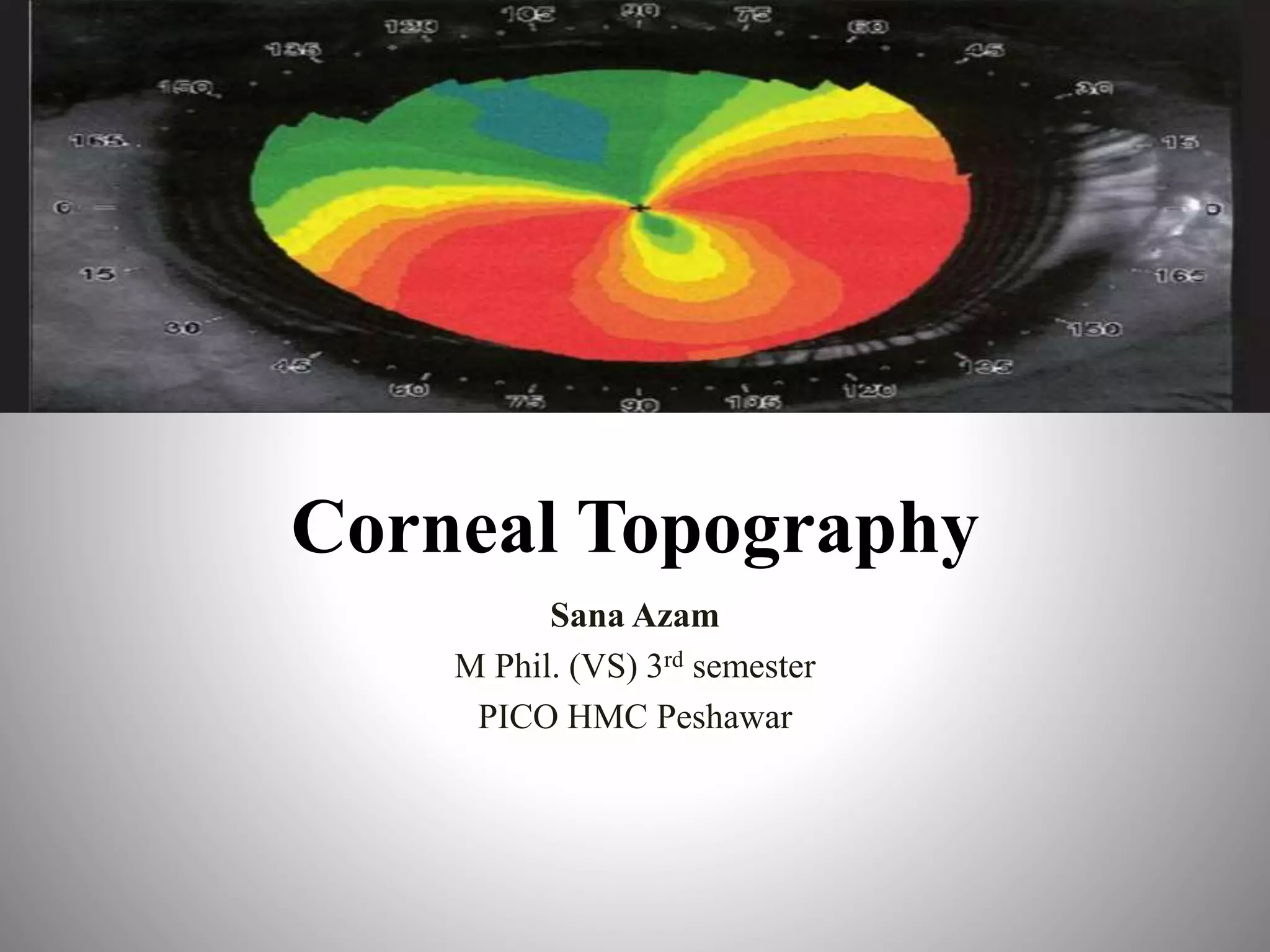
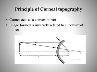
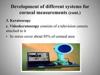
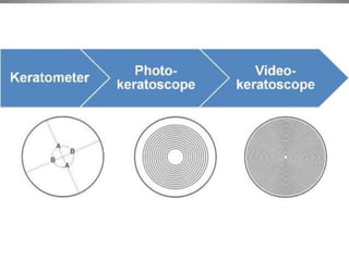
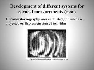
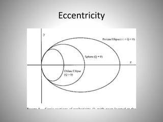
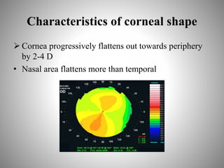
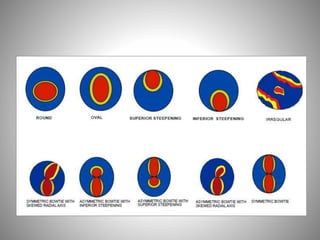
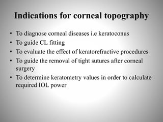
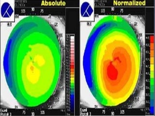
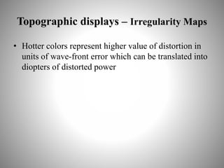
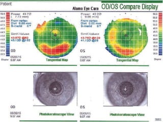
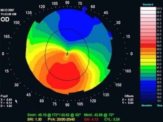
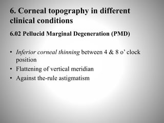
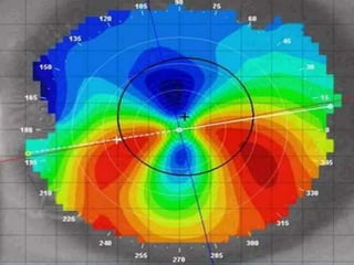
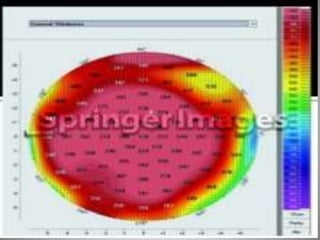
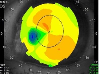
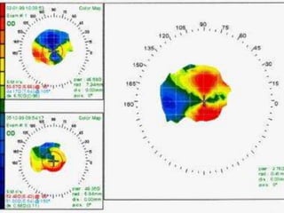
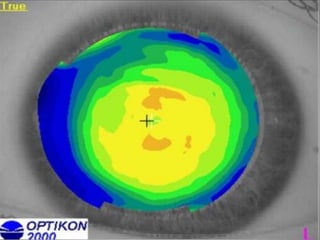
Corneal topography provides a non-invasive method to map the surface curvature of the cornea. Various techniques have been developed over time including keratometry, keratoscopy, rasterstereography, and interferometry. A normal topography map will show the cornea progressively flattening towards the periphery. Corneal topography is useful for diagnosing conditions like keratoconus by detecting irregular steepening, and for guiding contact lens or refractive surgery. Interpretation of topography maps involves analyzing features like color scales, axial maps, and topographic indices to evaluate the cornea's shape and detect any abnormalities.

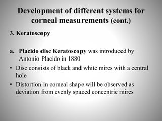
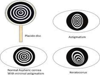
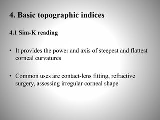


![PERI-PROSTHETIC FRACTURE NAIL-PLATE CONSTRUCT [NPC].pptx](https://cdn.slidesharecdn.com/ss_thumbnails/drarunkumardrmohamedashrafperiprostheticfrasturenail-plateconstructnpc-260209164459-7e9d15a1-thumbnail.jpg?width=640&height=640&fit=bounds)


