Downloaded 3,081 times


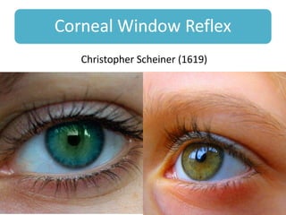
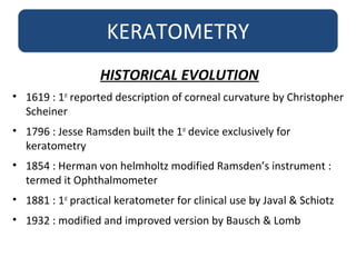
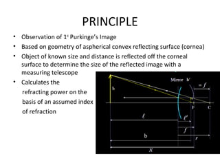
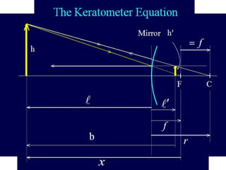
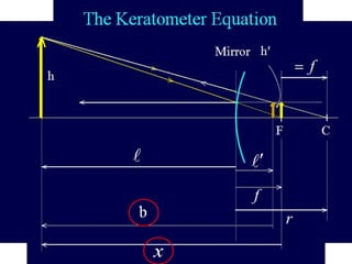
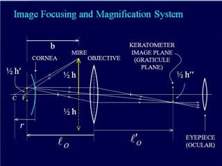
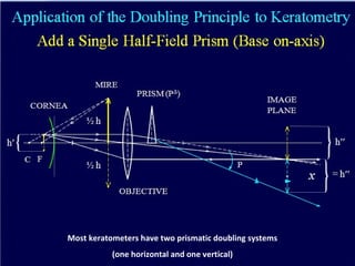


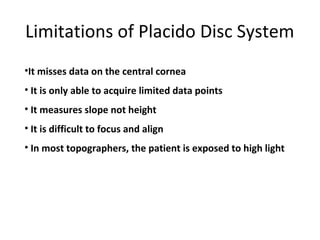
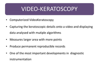
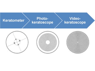
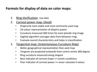
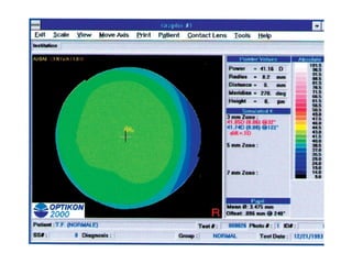

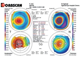
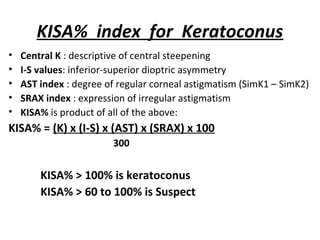
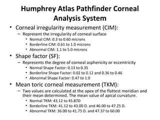
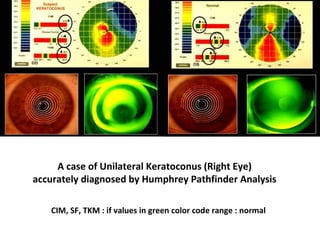


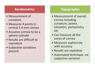
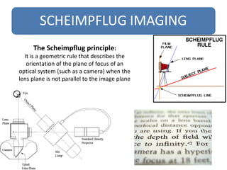
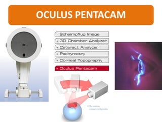


This document provides information about corneal topography and keratometry. It defines the cornea and its dimensions. It describes the historical evolution of keratometry from its first description in 1619 to modern computerized corneal topography systems. The document explains the principles, procedures, techniques, and applications of keratometry and corneal topography in evaluating the cornea. It also discusses the limitations and assumptions of keratometry measurements.


![APPROACH TO FEVER IN PEDIATRICS[1].pptTT](https://cdn.slidesharecdn.com/ss_thumbnails/approachtofeverinpediatrics1-260125081456-d559e079-thumbnail.jpg?width=640&height=640&fit=bounds)


