Downloaded 757 times
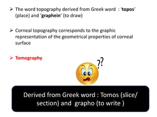
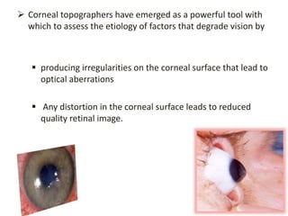
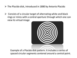
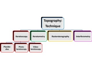
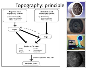
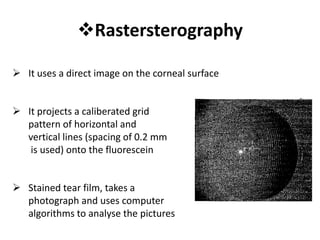
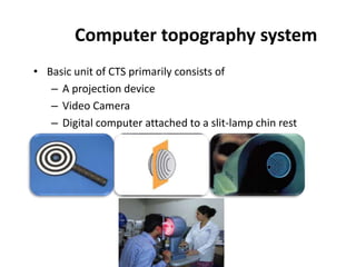
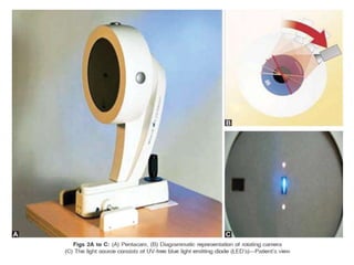
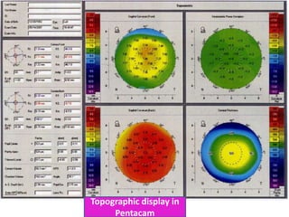


Corneal topography provides a graphic representation of the geometrical properties of the corneal surface. It uses techniques such as Placido disk, photokeratoscopy, videokeratoscopy, and slit imaging to map over 8000 points across the corneal surface. This provides detailed information about the shape and irregularities of the cornea which can then be used to diagnose conditions that degrade vision and guide treatment.


![Hypothalamus short ppt by Dr. Neha [PT].pptx](https://cdn.slidesharecdn.com/ss_thumbnails/hypothalamusbydr-260124145759-b9f94a93-thumbnail.jpg?width=640&height=640&fit=bounds)


