Downloaded 321 times

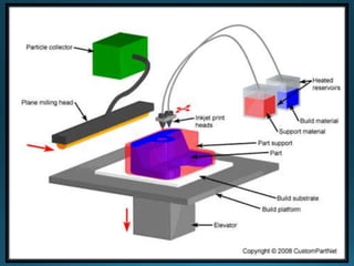
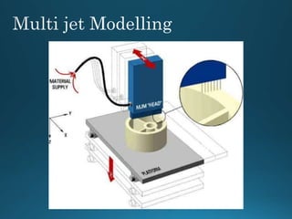

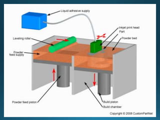


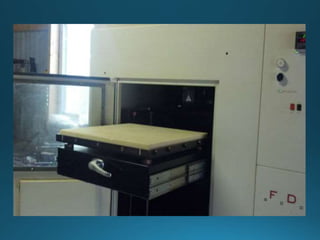

The document discusses several common ink jet printing techniques for additive manufacturing, including the Sanders Model Maker, Multi-Jet Modelling, Z402 Ink Jet System, and Genisys Xs printer. It describes the key components and processes of these systems, such as using ink jets to deposit liquid materials layer by layer, and how they are used to quickly produce prototypes and models.


