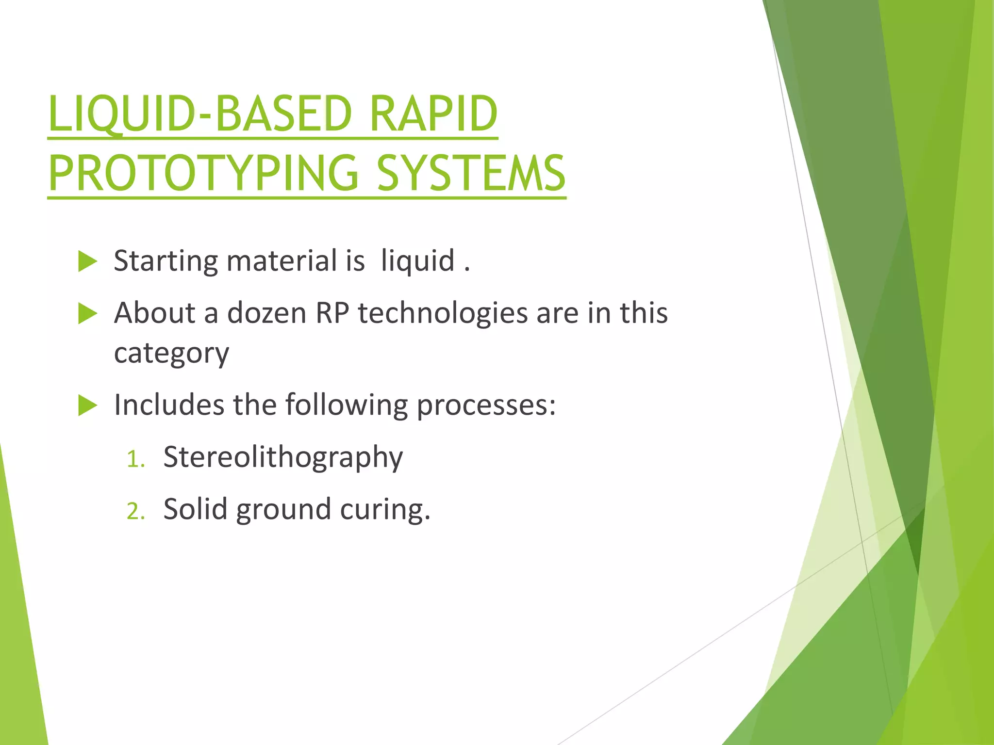
INTRODUCTION TO
RAPID
PROTOTYPING
Presented by,
ROLWYN MARIAN CARDOZA
1RV18MMD15
M.Tech MACHINE DESIGN
RV COLLEGE OF ENGINEERING.
What is a PROTOTYPE ?
A Prototype is an early sample, model or release of a
product built to test a concept or process or to act as a
thing to be replicated or learned from.
Prototypes are usually incomplete examples of what a
final product may look like.
RAPID PROTOTYPING
Rapid Prototyping is the "process of quickly
building and evaluating a series of prototypes" early
and often throughout the design process.
CATEGORIES:
Material removal RP
 This involves machining , milling
and drilling using CNC machines .
 Starting material is often a solid
block of wax which is very easy to
machine.
 Removed material and even
prototype can be reused when
no longer needed.
 Wood , plastics , metals can also
be used as starting materials.
Material addition RP
It involves adding layers of
material, one at a time to build
solid part from bottom to top.
Starting materials :
1) Liquid monomers
2) Solid sheets
3) Powders
COMMON PROCEDURE
LIQUID-BASED RAPID
PROTOTYPING SYSTEMS
 Starting material is liquid .
 About a dozen RP technologies are in this
category
 Includes the following processes:
1. Stereolithography
2. Solid ground curing.
STEREOLITHOGRAPHY (STL)
RP process for fabricating a solid plastic part out of a
photosensitive liquid polymer using a directed laser beam
to solidify the polymer.
 Each layer is 0.076 to 0.50mm thick
 Scan speeds of STL lasers typically range between 500 and
2500 mm/s.
 The time required to build the part by this layering process
ranges from 1hour for small parts of simple geometry up to
several dozen hours for complex parts.
 After all of the layers have been formed, the photopolymer is
about 95% cured. The piece is therefore ‘‘baked’’ in a
fluorescent oven to completely solidify the polymer.
SOLID GROUND CURING
1 2
3 4 5
6 7
8 9 10
 The sequence for each layer takes about 90 seconds.
 The hardening process takes 2 to 3 seconds for each
layer.
 Although we have described SGC as a sequential
process, certain steps (masking) are accomplished in
parallel.
 Throughput time to produce a part by SGC is claimed to
be about eight times faster than competing RP systems.
SOLID-BASED RAPID PROTOTYPING
SYSTEMS
 Starting material is a solid.
 Solid-based RP systems include the following
processes:
1. Laminated object manufacturing
2. Fused deposition modeling.
LAMINATED OBJECT
MANUFACTURING (LOM)
1. Platform
2. Feed roller
3. Heated lamination
roller
4. Laser cutter
 Sheet thickness is 0.05 to 0.50 mm.
 The laser is typically a 25 or 50 W CO2 laser.
 A sealing application is recommended, using a urethane,
epoxy, or other polymer spray to prevent moisture
absorption and damage.
 LOM part sizes can be relatively large among RP
processes, with work volumes up to 800 mm* 500 mm*
550 mm.
FUSED DEPOSITION MODELING
 Filament diameter= 1.25 mm.
 The extrudate is solidified and cold welded to the cooler
part surface in about 0.1 second.
 The layer thickness can be set anywhere from 0.05 to
0.75mm.
 About 400mm of filament material can be deposited per
second by the extrusion workhead.
POWDER-BASED RP SYSTEMS
 Starting material is powder.
 Powder-based RP systems include the following:
1. Selective laser sintering
2. Three dimensional printing
 A wide range of thermoplastics, composites, metals and
ceramics can be used in this process, thus providing an
extensive range of functional parts to be built
SELECTIVE LASER SINTERING
(SLS)
 Layer thickness is 0.075 to 0.50 mm
 Materials in SLS include polyvinylchloride,
polycarbonate, polyester, polyurethane, ABS, nylon, and
investment casting wax. These materials are less
expensive than the photosensitive resins used in
stereolithography.
Three-Dimensional Printing
(3DP)
 Starting materials in 3DP are powders of ceramic, metal,
or cermet, and binders are polymeric or colloidal silica
or silicon carbide
 Typical layer thickness ranges from 0.10 to 0.18 mm.
 The ink-jet printing head moves across the layer at a
speed of about 1.5 m/s .
 The sweep time, together with the spreading of the
powders, permits a cycle time per layer of about 2
seconds
Rapid prototyping( additive manufacturing)

Rapid prototyping( additive manufacturing)

  • 1.
    INTRODUCTION TO RAPID PROTOTYPING Presented by, ROLWYNMARIAN CARDOZA 1RV18MMD15 M.Tech MACHINE DESIGN RV COLLEGE OF ENGINEERING.
  • 2.
    What is aPROTOTYPE ? A Prototype is an early sample, model or release of a product built to test a concept or process or to act as a thing to be replicated or learned from. Prototypes are usually incomplete examples of what a final product may look like.
  • 3.
    RAPID PROTOTYPING Rapid Prototypingis the "process of quickly building and evaluating a series of prototypes" early and often throughout the design process.
  • 4.
    CATEGORIES: Material removal RP This involves machining , milling and drilling using CNC machines .  Starting material is often a solid block of wax which is very easy to machine.  Removed material and even prototype can be reused when no longer needed.  Wood , plastics , metals can also be used as starting materials. Material addition RP It involves adding layers of material, one at a time to build solid part from bottom to top. Starting materials : 1) Liquid monomers 2) Solid sheets 3) Powders
  • 5.
  • 6.
    LIQUID-BASED RAPID PROTOTYPING SYSTEMS Starting material is liquid .  About a dozen RP technologies are in this category  Includes the following processes: 1. Stereolithography 2. Solid ground curing.
  • 7.
    STEREOLITHOGRAPHY (STL) RP processfor fabricating a solid plastic part out of a photosensitive liquid polymer using a directed laser beam to solidify the polymer.
  • 8.
     Each layeris 0.076 to 0.50mm thick  Scan speeds of STL lasers typically range between 500 and 2500 mm/s.  The time required to build the part by this layering process ranges from 1hour for small parts of simple geometry up to several dozen hours for complex parts.  After all of the layers have been formed, the photopolymer is about 95% cured. The piece is therefore ‘‘baked’’ in a fluorescent oven to completely solidify the polymer.
  • 9.
  • 10.
  • 11.
     The sequencefor each layer takes about 90 seconds.  The hardening process takes 2 to 3 seconds for each layer.  Although we have described SGC as a sequential process, certain steps (masking) are accomplished in parallel.  Throughput time to produce a part by SGC is claimed to be about eight times faster than competing RP systems.
  • 12.
    SOLID-BASED RAPID PROTOTYPING SYSTEMS Starting material is a solid.  Solid-based RP systems include the following processes: 1. Laminated object manufacturing 2. Fused deposition modeling.
  • 13.
    LAMINATED OBJECT MANUFACTURING (LOM) 1.Platform 2. Feed roller 3. Heated lamination roller 4. Laser cutter
  • 14.
     Sheet thicknessis 0.05 to 0.50 mm.  The laser is typically a 25 or 50 W CO2 laser.  A sealing application is recommended, using a urethane, epoxy, or other polymer spray to prevent moisture absorption and damage.  LOM part sizes can be relatively large among RP processes, with work volumes up to 800 mm* 500 mm* 550 mm.
  • 15.
  • 16.
     Filament diameter=1.25 mm.  The extrudate is solidified and cold welded to the cooler part surface in about 0.1 second.  The layer thickness can be set anywhere from 0.05 to 0.75mm.  About 400mm of filament material can be deposited per second by the extrusion workhead.
  • 17.
    POWDER-BASED RP SYSTEMS Starting material is powder.  Powder-based RP systems include the following: 1. Selective laser sintering 2. Three dimensional printing  A wide range of thermoplastics, composites, metals and ceramics can be used in this process, thus providing an extensive range of functional parts to be built
  • 18.
  • 19.
     Layer thicknessis 0.075 to 0.50 mm  Materials in SLS include polyvinylchloride, polycarbonate, polyester, polyurethane, ABS, nylon, and investment casting wax. These materials are less expensive than the photosensitive resins used in stereolithography.
  • 20.
  • 21.
     Starting materialsin 3DP are powders of ceramic, metal, or cermet, and binders are polymeric or colloidal silica or silicon carbide  Typical layer thickness ranges from 0.10 to 0.18 mm.  The ink-jet printing head moves across the layer at a speed of about 1.5 m/s .  The sweep time, together with the spreading of the powders, permits a cycle time per layer of about 2 seconds

Editor's Notes

  • #3 1) Help development team think ,plan,ex