Download to read offline


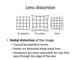
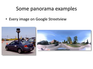
![Radial distortion
[Image credit: J. Bouguet http://www.vision.caltech.edu/bouguetj/calib_doc/htmls/example.html]
• Arrows show motion
of projected points
relative to an ideal
(distortion-free lens)](https://image.slidesharecdn.com/lec11panoramas-200719140204/85/Computer-Vision-panoramas-21-320.jpg)
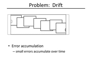
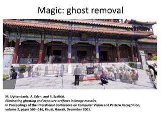
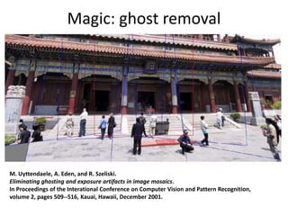
![Problem: Drift
• Solution
– add another copy of first image at the end
– this gives a constraint: yn = y1
– there are a bunch of ways to solve this problem
• add displacement of (y1 – yn)/(n -1) to each image after the first
• apply an affine warp: y’ = y + ax [you will implement this for P3]
• run a big optimization problem, incorporating this constraint
– best solution, but more complicated
– known as “bundle adjustment”
(x1,y1)
copy of first image
(xn,yn)](https://image.slidesharecdn.com/lec11panoramas-200719140204/85/Computer-Vision-panoramas-43-320.jpg)
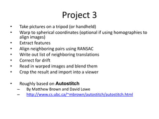
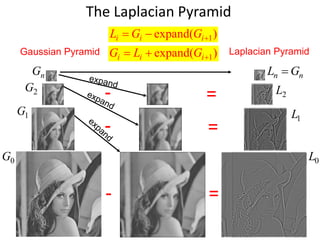
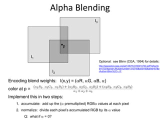
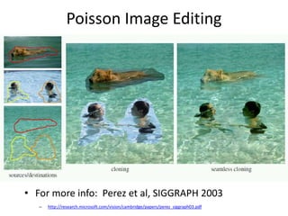
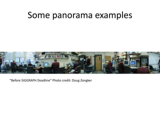


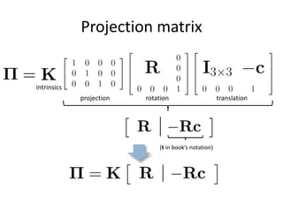
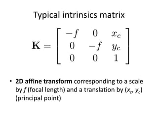
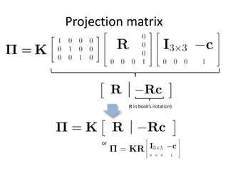
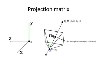
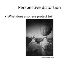
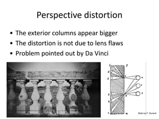
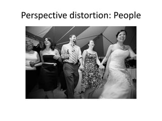
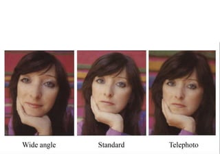
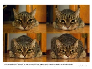
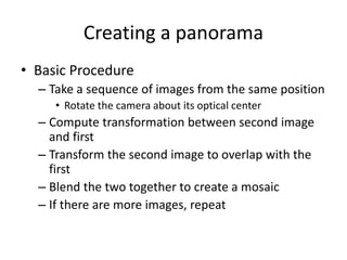
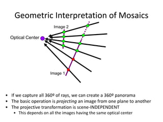
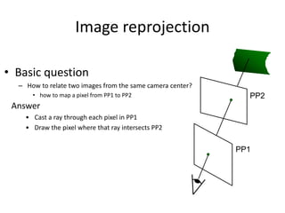
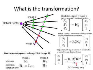
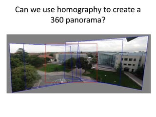
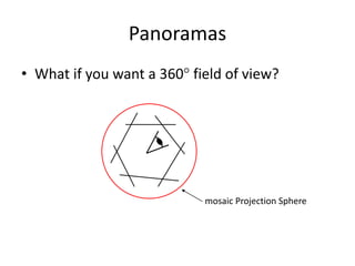
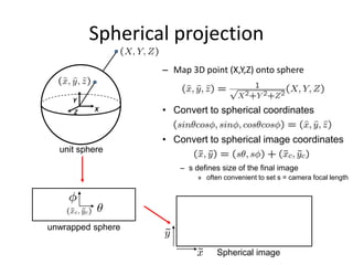
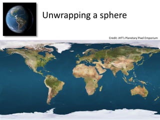
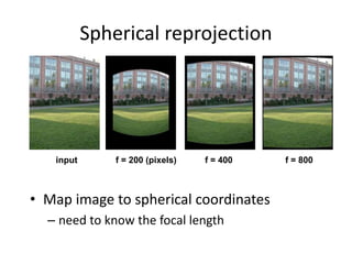
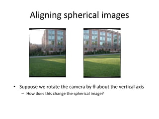
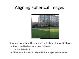
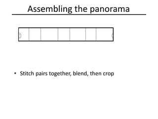
This document discusses panoramas and techniques for creating panoramic images from multiple photographs. It begins with announcements about an upcoming project on panorama stitching and a midterm exam. It then reviews camera projection models and discusses various types of lens distortion and image projections. The remainder of the document focuses on creating panoramas, including aligning images, correcting for drift, blending images, and examples of panoramas.