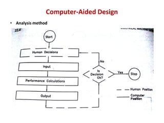
Download as PDF, PPTX
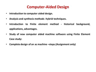


The document discusses computer-aided design (CAD) methods for electrical machines, including analysis, synthesis, and hybrid approaches, emphasizing the importance of computer programs for managing high variable counts in design. It introduces the finite element method (FEM) as a numerical technique for solving complex engineering problems and highlights its historical development and advantages in design optimization. The content also outlines input data requirements, various design parameters, and the role of FEM in enhancing engineering methodologies and reducing product development time.