Downloaded 111 times
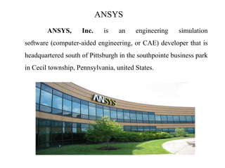
![STATIC ANALYSIS
In static analysis, the load or field conditions do not vary with respect
to time and therefore it is assumed that the load or field conditions applied
gradually not suddenly. The system under this analysis can be linier or
nonlinear. The inertia and damping effects are ignored in static analysis.
[k] {X} = {f}
Where,
[k] = stiffness matrix
{X} = displacement matrix
{f} = load matrix
The above equation is called the force balanced equation for the liner
system. If the elements of matrix [k] are the function of {x}, the system is
known as nonlinear system. Nonlinear system includes large deformation,
plasticity, creep and s on.](https://image.slidesharecdn.com/cae-introduction-180719184500/85/COMPUTER-AIDED-ENGINEERING-INTRODUCTION-22-320.jpg)
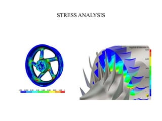

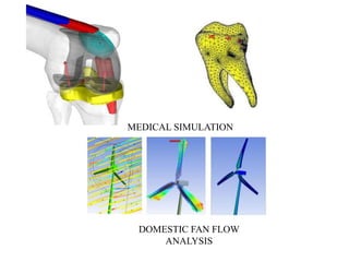
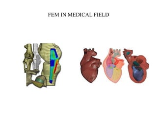
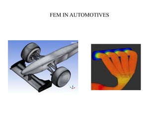
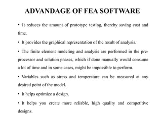
Computer Aided Engineering (CAE) uses computer software to simulate product performance in order to improve designs. The CAE process involves pre-processing to create models, solving using mathematical physics, and post-processing results. CAE allows designs to be evaluated using simulation rather than prototypes, saving time and money. Finite Element Analysis is a numerical technique used in CAE to approximate solutions to engineering problems. Common CAE applications include stress analysis, thermal/fluid analysis, and manufacturing simulation.