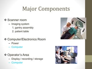
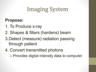
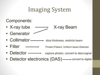
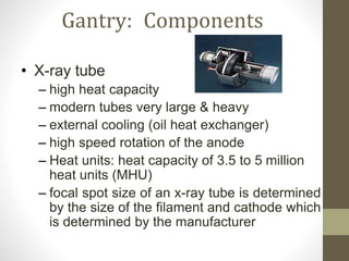
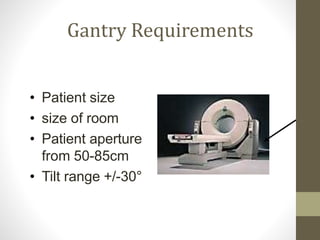
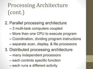
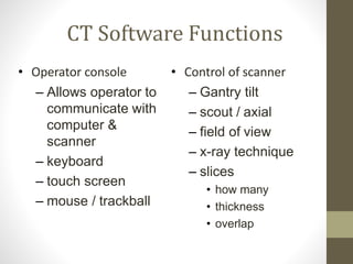
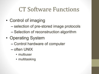
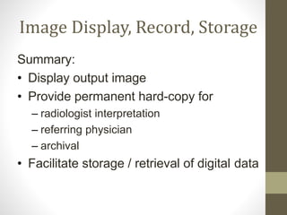
ComputedTomography
Components
Three Major Systems
 Imaging System
 Computer System
 Image Display/Recording/Storage
System
 Each system in a separate
room
Major Components
 Scanner room
– Imaging system
1. gantry assembly
2. patient table
 Computer/Electronics Room
– Power
– Computer
– Generator
 Operator’s Area
– Display / recording / storage
– Computer
Imaging System
Propose:
1. To Produce x-ray
2. Shapes & filters (hardens) beam
3.Detect (measure) radiation passing
through patient
4. Convert transmitted photons
– Provides digital intensity data to computer
Imaging System
Components:
X-ray Beam
slice thickness, restricts beam
Protect Patient, Uniform beam-Detector
• X-ray tube
• Generator
• Collimator
• Filter
• Detector capture photon, convert to elect.signal
• Detector electronics (DAS) convert to digital
Gantry Assembly
 All previous components in
Gantry Assembly
 Moving Frame, Tilt, Gantry aperture
 Rotational components including slip
ring , positioning laser lights,
Gantry: Components
• X-ray tube
– high heat capacity
– modern tubes very large & heavy
– external cooling (oil heat exchanger)
– high speed rotation of the anode
– Heat units: heat capacity of 3.5 to 5 million
heat units (MHU)
– focal spot size of an x-ray tube is determined
by the size of the filament and cathode which
is determined by the manufacturer
Gantry: Components
• Generator, inside gantry
– supplies power to x-ray tube
• filament
• high voltage
– Different power 30-60Kilowatts
– Allowing range of exposure techniques:
80,100,120,130,and 140kV and
30,50,65,100,125,150,175, and 200,mA
Gantry: Components
• Collimators
– Tube/Source collimators: restricts beam to
slice of interest
– Pre-patient collimators: maintain the width of
the beam as it travels toward the patient
– Post-patient/Pre-detector collimators: below
patient and above detector proper beam
width at detector and reduce no. of
scattered photons at detector
Gantry: Components
• Filter
– protects patient from low-energy photons
– provides a beam closer to mono-energetic
– provides a more uniform beam (hardening)
• Mathematical filtration: bone/tissue algorithms
(recons. Process)
• Inherent tube filtration
• Filters made of aluminum or Teflon; to shape
beam-low energy photons and scatter
Gantry Components
• Detector = image receptor
• beam travels through patient and
attenuates by the anatomical structures it
passes through
• Job: collect attenuated photon energy
and convert it to electrical signal, which
will then be converted to a digital signal
for computer reconstruction
Detectors
• Crystal or ionizing gas
• When struck by x-ray photon , produces light or electrical
energy
• Two types : scintillation or solid state and xenon gas
detectors
• Scintillation detectors- uses a crystal that fluoresces
when struck by x-ray photon which produces light energy
– A photodiode, attached to scintillation portion, transforms light
energy into electrical or analog energy
– Strength of the detector signal is proportional to number of
attenuated photons that are successfully converted to light
energy and then to an electrical signal
A Note on Detectors
• Detector: single element of detector array,
produces electrical/light signal as a response to
x-rays
• Detector array: total number of detectors that a
CT system utilizes for collecting attenuated
information
• A Ray: path that an x-ray beam travels from
tube to a single detector
• Detector reads each ray and measures resultant
beam attenuation
Cont.
• Ray Sum: attenuation measurement of
each ray
• Projection (view): a complete set of ray
sums
– It takes many projections to createa
computed tomography image
Gantry Components
• Detector electronics, data
acquisition system (DAS)
– Receives weak signal form detector
– includes A-D converter
– Amplification
• provides digital information to
reconstruction computer
Gantry Requirements
• Patient size
• size of room
• Patient aperture
from 50-85cm
• Tilt range +/-30°
Patient Couch
Strong, safe, and hygienic, made of
radiolucent material
1.Couch top: carbon fiber composite, low
absorption
2.Pedestal: mechanical and electrical
components
Patient Couch
• Vertical travel
– minimum height for stretcher transfer
• Horizontal travel
– reduces need for re-positioning patient
– accuracy
Patient Couch Requirements
• Radiolucent
• Easy to clean
• Weight limits: 450lb
• Total travel: 180cm
• Accuracy: +/- 0.25mm
• Speed: 25mm/sec
Computer System
• Receives digital data from DAS
• Reconstructs cross-sectional image
• Image display, manipulation, & processing
– windowing
– enhancement
– zoom
– quantitative measurements
– multi-planar & 3D reconstruction
Computer System Components
• Input / output
devices
– Detectors
– Printer
• Central processing
units (CPU’s)
• Array Processor
– Reconstruction
Hardware
 Interfaces to other
computers
• Remote service
• RIS
• Archive
• Web browser
 Communications hardware
 Software
• enables above hardware
operation
• image manipulation
• scanning control
Computer System
• Processing architecture
• Hardware
• Software
Processing
Architecture
Capable of Multi-processing
– Scanning, reconstructing, archiving
Three Types:
1. Pipeline processing architecture
– various reconstruction steps may be
performed by separate processors
– Very fast image reconstruction, after
scanning image can be viewed
– Overlapping moving data into pipe
Processing Architecture
(cont.)
2. Parallel processing architecture
– 3 multi-task computers coupled
– More than one CPU to execute program
– Coordination, dividing program instructions
– separate scan, display, & file processors
3. Distributed processing architecture
– many independent processors
– each controls specific function
– each runs a different activity
CT Software Functions
• Operator console
– Allows operator to
communicate with
computer &
scanner
– keyboard
– touch screen
– mouse / trackball
• Control of scanner
– Gantry tilt
– scout / axial
– field of view
– x-ray technique
– slices
• how many
• thickness
• overlap
CT Software Functions
• Control of imaging
– selection of pre-stored image protocols
– Selection of reconstruction algorithm
• Operating System
– Control hardware of computer
– often UNIX
• multiuser
• multitasking
Image Display, Record, Storage
Summary:
• Display output image
• Provide permanent hard-copy for
– radiologist interpretation
– referring physician
– archival
• Facilitate storage / retrieval of digital data
Image Display
• Display
– CRT or flat panel
• images in gray shade
• non-image data in color or
• often hi-resolution
• Can display 4-on-1 or zoomed image at
full resolution
• Display processor provides
– display functions
– image manipulation
Image Storage
• Storage:
• 512x512x2 bytes (16bits) deep
• Requires 0.5MB storage
• 1 Examination= 50 images, 25MB
• 50/day = 1.25GB
Image Size
• 512 X 512 image = 262144
pixels
• 262144 pixels X 2 bytes / pixel =
524288 bytes per image ~ 512
KB ~ 0.5 MB
High Capacity Image Storage
• Magnetic disk
• Magnetic tape
• Digital videotape
• Optical disks
• Optical Tape
• Capacity
• Access Speed
• Rewritable?
• Size / space
• $$
Types Considerations
CT Hard Copy on Laser Printer
• Requirements for hard copy
–broad gray-scale contrast
resolution
–high spatial resolution
• Two types :
• Solid state and gas lasers
Laser Printing
• Unexposed film will move to exposure
region, film exposed by scanning line by
line with laser
• Producing a latent image
CT Console
• Keyboard
– Alphanumeric,
special function
keys, trackball,
windowing controls
• Display
– CRT
– Flat panel
– Touch panel
CT Console Allows Operator to
Control
• Gantry tilt
• scanning parameters
– Slice thickness
– Spacing
– Technique
• image manipulation
– multiplanar reformatting
– 3D
– zoom / pan
Control
Functions
• Archiving
• Voice instruction to patient
• Visual instructions to patient
• Filming protocols
– Window / level (for contrast)
– Format (12 on 1 for example)
Options and Accessories
Hardware:
• Archival systems
• Independent workstations
– Physicians
– 3D
• Printing
– Laser
– Multi-format
CT Options
• Software:
• Bone mineral analysis
• Dynamic scan
– rapid sequential scans of singleslice
• Multiplanar reformatting
• 3D image reconstruction
• Regional cerebral blood flow analysis
• CT Angiography
• Dental CT (surgery planning, implants)
• Networking
Accessories
• Support – immobilization
• Pads, wedges, head rests, straps,
mattress, knee support pad
CT Room Layout
Scanning Room:
• Gantry, Patient Couch
• Room for
– Resuscitation team
– Emergency equipment
– Stretchers
• Medical Gasses
• Shielding
CT Room Layout
Equipment room/Computer
– Host computer and computing equipment
• Control room
– Control console, film recording equipment
Purchasing
Specifications
• List of Items
– Major components
– Optional equipment
• Major technical features
– should be measurable
CT Specifications Who’s
Involved?
• Radiologist
• Technologist
• Physicist
• Biomedical Engineer
• IT
• Engineering Management (new)
Technical Specifications
• X-ray
generator
parameters
– operational parameters
• maximum kVp
• kW rating
• X-ray tube
– heat capacity
– cooling rates
• Detector
efficiency
• Reconstruction
time
CT Specifications
• Gantry
– aperture size
– tilt range
– laser positioning aids
– controls
• Couch
– strength / weight limits
– movement characteristics
• Speed
• Limits
CT Specifications Operator’s
Console
• Display, keyboard,
mouse, touch panel
characteristics
• Software design
– Choice box of available
options vs. manual typing
• Film recording &
archival considerations
CT Specifications
• Physician’s console & other
workstations
– functions available
– speed
– Simultaneity
• Computer
– storage requirements
– CPU
– networking
CT Specifications
• Interfaces
• PACS hooks & DICOM (digital imaging and
communication in medicine ) compatibility
– Worklist management
• Pulling patient demographics from RIS (
radiology information system )
– Image storage
• Transfer of images to archive / PACS
Computer Software CT
Specifications
• image reconstruction options
– FOV
– filters
• display options
– Annotation ( syntactic metadata)
• analysis options
– regions of interest
CT Specifications
• Hardcopy devices &
interface
– laser printer
• Quality control
equipment
– phantoms
– software
• Remote Diagnostics
CT Specifications
• Acceptance Testing
– Who performs
– What tests done
• Technology Changes
– “Latest model available at
time of delivery”
• Service
– Warranty
– Binding service contract
prices
Room Requirements
• Scanner Room
• Console Area
• Computer Room
• Design
CT Specifications Training
• For whom?
– Technologists
– How many?
• Where?
– Vendor site
– On-site
– Local
• What’s included
– Registration
– Books
– Travel expenses
CT COMPONENTS

CT COMPONENTS

  • 1.
  • 2.
    Three Major Systems Imaging System  Computer System  Image Display/Recording/Storage System  Each system in a separate room
  • 3.
    Major Components  Scannerroom – Imaging system 1. gantry assembly 2. patient table  Computer/Electronics Room – Power – Computer – Generator  Operator’s Area – Display / recording / storage – Computer
  • 4.
    Imaging System Propose: 1. ToProduce x-ray 2. Shapes & filters (hardens) beam 3.Detect (measure) radiation passing through patient 4. Convert transmitted photons – Provides digital intensity data to computer
  • 5.
    Imaging System Components: X-ray Beam slicethickness, restricts beam Protect Patient, Uniform beam-Detector • X-ray tube • Generator • Collimator • Filter • Detector capture photon, convert to elect.signal • Detector electronics (DAS) convert to digital
  • 6.
    Gantry Assembly  Allprevious components in Gantry Assembly  Moving Frame, Tilt, Gantry aperture  Rotational components including slip ring , positioning laser lights,
  • 7.
    Gantry: Components • X-raytube – high heat capacity – modern tubes very large & heavy – external cooling (oil heat exchanger) – high speed rotation of the anode – Heat units: heat capacity of 3.5 to 5 million heat units (MHU) – focal spot size of an x-ray tube is determined by the size of the filament and cathode which is determined by the manufacturer
  • 8.
    Gantry: Components • Generator,inside gantry – supplies power to x-ray tube • filament • high voltage – Different power 30-60Kilowatts – Allowing range of exposure techniques: 80,100,120,130,and 140kV and 30,50,65,100,125,150,175, and 200,mA
  • 9.
    Gantry: Components • Collimators –Tube/Source collimators: restricts beam to slice of interest – Pre-patient collimators: maintain the width of the beam as it travels toward the patient – Post-patient/Pre-detector collimators: below patient and above detector proper beam width at detector and reduce no. of scattered photons at detector
  • 10.
    Gantry: Components • Filter –protects patient from low-energy photons – provides a beam closer to mono-energetic – provides a more uniform beam (hardening) • Mathematical filtration: bone/tissue algorithms (recons. Process) • Inherent tube filtration • Filters made of aluminum or Teflon; to shape beam-low energy photons and scatter
  • 11.
    Gantry Components • Detector= image receptor • beam travels through patient and attenuates by the anatomical structures it passes through • Job: collect attenuated photon energy and convert it to electrical signal, which will then be converted to a digital signal for computer reconstruction
  • 12.
    Detectors • Crystal orionizing gas • When struck by x-ray photon , produces light or electrical energy • Two types : scintillation or solid state and xenon gas detectors • Scintillation detectors- uses a crystal that fluoresces when struck by x-ray photon which produces light energy – A photodiode, attached to scintillation portion, transforms light energy into electrical or analog energy – Strength of the detector signal is proportional to number of attenuated photons that are successfully converted to light energy and then to an electrical signal
  • 13.
    A Note onDetectors • Detector: single element of detector array, produces electrical/light signal as a response to x-rays • Detector array: total number of detectors that a CT system utilizes for collecting attenuated information • A Ray: path that an x-ray beam travels from tube to a single detector • Detector reads each ray and measures resultant beam attenuation
  • 14.
    Cont. • Ray Sum:attenuation measurement of each ray • Projection (view): a complete set of ray sums – It takes many projections to createa computed tomography image
  • 15.
    Gantry Components • Detectorelectronics, data acquisition system (DAS) – Receives weak signal form detector – includes A-D converter – Amplification • provides digital information to reconstruction computer
  • 16.
    Gantry Requirements • Patientsize • size of room • Patient aperture from 50-85cm • Tilt range +/-30°
  • 17.
    Patient Couch Strong, safe,and hygienic, made of radiolucent material 1.Couch top: carbon fiber composite, low absorption 2.Pedestal: mechanical and electrical components
  • 18.
    Patient Couch • Verticaltravel – minimum height for stretcher transfer • Horizontal travel – reduces need for re-positioning patient – accuracy
  • 19.
    Patient Couch Requirements •Radiolucent • Easy to clean • Weight limits: 450lb • Total travel: 180cm • Accuracy: +/- 0.25mm • Speed: 25mm/sec
  • 20.
    Computer System • Receivesdigital data from DAS • Reconstructs cross-sectional image • Image display, manipulation, & processing – windowing – enhancement – zoom – quantitative measurements – multi-planar & 3D reconstruction
  • 21.
    Computer System Components •Input / output devices – Detectors – Printer • Central processing units (CPU’s) • Array Processor – Reconstruction Hardware  Interfaces to other computers • Remote service • RIS • Archive • Web browser  Communications hardware  Software • enables above hardware operation • image manipulation • scanning control
  • 22.
    Computer System • Processingarchitecture • Hardware • Software
  • 23.
    Processing Architecture Capable of Multi-processing –Scanning, reconstructing, archiving Three Types: 1. Pipeline processing architecture – various reconstruction steps may be performed by separate processors – Very fast image reconstruction, after scanning image can be viewed – Overlapping moving data into pipe
  • 24.
    Processing Architecture (cont.) 2. Parallelprocessing architecture – 3 multi-task computers coupled – More than one CPU to execute program – Coordination, dividing program instructions – separate scan, display, & file processors 3. Distributed processing architecture – many independent processors – each controls specific function – each runs a different activity
  • 25.
    CT Software Functions •Operator console – Allows operator to communicate with computer & scanner – keyboard – touch screen – mouse / trackball • Control of scanner – Gantry tilt – scout / axial – field of view – x-ray technique – slices • how many • thickness • overlap
  • 26.
    CT Software Functions •Control of imaging – selection of pre-stored image protocols – Selection of reconstruction algorithm • Operating System – Control hardware of computer – often UNIX • multiuser • multitasking
  • 27.
    Image Display, Record,Storage Summary: • Display output image • Provide permanent hard-copy for – radiologist interpretation – referring physician – archival • Facilitate storage / retrieval of digital data
  • 28.
    Image Display • Display –CRT or flat panel • images in gray shade • non-image data in color or • often hi-resolution • Can display 4-on-1 or zoomed image at full resolution • Display processor provides – display functions – image manipulation
  • 29.
    Image Storage • Storage: •512x512x2 bytes (16bits) deep • Requires 0.5MB storage • 1 Examination= 50 images, 25MB • 50/day = 1.25GB
  • 30.
    Image Size • 512X 512 image = 262144 pixels • 262144 pixels X 2 bytes / pixel = 524288 bytes per image ~ 512 KB ~ 0.5 MB
  • 31.
    High Capacity ImageStorage • Magnetic disk • Magnetic tape • Digital videotape • Optical disks • Optical Tape • Capacity • Access Speed • Rewritable? • Size / space • $$ Types Considerations
  • 32.
    CT Hard Copyon Laser Printer • Requirements for hard copy –broad gray-scale contrast resolution –high spatial resolution • Two types : • Solid state and gas lasers
  • 33.
    Laser Printing • Unexposedfilm will move to exposure region, film exposed by scanning line by line with laser • Producing a latent image
  • 34.
    CT Console • Keyboard –Alphanumeric, special function keys, trackball, windowing controls • Display – CRT – Flat panel – Touch panel
  • 35.
    CT Console AllowsOperator to Control • Gantry tilt • scanning parameters – Slice thickness – Spacing – Technique • image manipulation – multiplanar reformatting – 3D – zoom / pan
  • 36.
    Control Functions • Archiving • Voiceinstruction to patient • Visual instructions to patient • Filming protocols – Window / level (for contrast) – Format (12 on 1 for example)
  • 37.
    Options and Accessories Hardware: •Archival systems • Independent workstations – Physicians – 3D • Printing – Laser – Multi-format
  • 38.
    CT Options • Software: •Bone mineral analysis • Dynamic scan – rapid sequential scans of singleslice • Multiplanar reformatting • 3D image reconstruction • Regional cerebral blood flow analysis • CT Angiography • Dental CT (surgery planning, implants) • Networking
  • 39.
    Accessories • Support –immobilization • Pads, wedges, head rests, straps, mattress, knee support pad
  • 40.
    CT Room Layout ScanningRoom: • Gantry, Patient Couch • Room for – Resuscitation team – Emergency equipment – Stretchers • Medical Gasses • Shielding
  • 41.
    CT Room Layout Equipmentroom/Computer – Host computer and computing equipment • Control room – Control console, film recording equipment
  • 42.
    Purchasing Specifications • List ofItems – Major components – Optional equipment • Major technical features – should be measurable
  • 43.
    CT Specifications Who’s Involved? •Radiologist • Technologist • Physicist • Biomedical Engineer • IT • Engineering Management (new)
  • 44.
    Technical Specifications • X-ray generator parameters –operational parameters • maximum kVp • kW rating • X-ray tube – heat capacity – cooling rates • Detector efficiency • Reconstruction time
  • 45.
    CT Specifications • Gantry –aperture size – tilt range – laser positioning aids – controls • Couch – strength / weight limits – movement characteristics • Speed • Limits
  • 46.
    CT Specifications Operator’s Console •Display, keyboard, mouse, touch panel characteristics • Software design – Choice box of available options vs. manual typing • Film recording & archival considerations
  • 47.
    CT Specifications • Physician’sconsole & other workstations – functions available – speed – Simultaneity • Computer – storage requirements – CPU – networking
  • 48.
    CT Specifications • Interfaces •PACS hooks & DICOM (digital imaging and communication in medicine ) compatibility – Worklist management • Pulling patient demographics from RIS ( radiology information system ) – Image storage • Transfer of images to archive / PACS
  • 49.
    Computer Software CT Specifications •image reconstruction options – FOV – filters • display options – Annotation ( syntactic metadata) • analysis options – regions of interest
  • 50.
    CT Specifications • Hardcopydevices & interface – laser printer • Quality control equipment – phantoms – software • Remote Diagnostics
  • 51.
    CT Specifications • AcceptanceTesting – Who performs – What tests done • Technology Changes – “Latest model available at time of delivery” • Service – Warranty – Binding service contract prices
  • 52.
    Room Requirements • ScannerRoom • Console Area • Computer Room • Design
  • 53.
    CT Specifications Training •For whom? – Technologists – How many? • Where? – Vendor site – On-site – Local • What’s included – Registration – Books – Travel expenses