Downloaded 1,058 times


![Image intensifier parameters (I) Conversion coefficient ( Gx ): the ratio of the output screen brightness to the input screen dose rate [ cd.m -2 Gys -1 ] Gx depends on the quality of the incident beam ( IEC publication 573 recommends HVL of 7 0.2 mm Al) Gx depends on : the applied tube potential the diameter ( ) of the input screen I.I. input screen ( ) of 22 cm Gx = 200 I.I. input screen ( ) of 16 cm Gx = 200 x (16/22) 2 = 105 I.I. input screen ( ) of 11 cm Gx = 200 x (11/22) 2 = 50](https://image.slidesharecdn.com/fluoroscopysystems-100510211313-phpapp01/85/Fluoroscopy-systems-19-320.jpg)
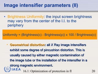
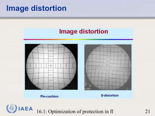
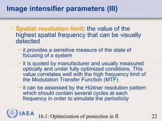
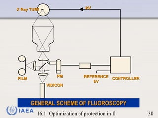
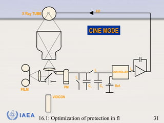
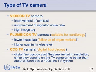
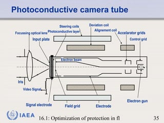
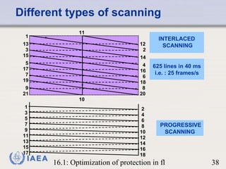
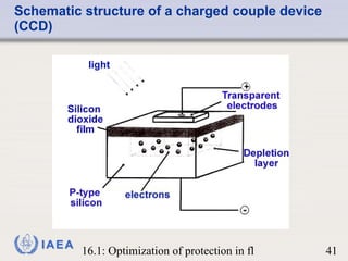
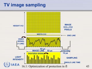
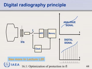

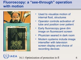
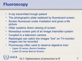
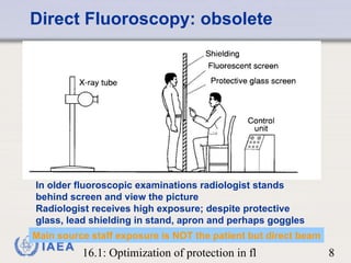
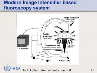
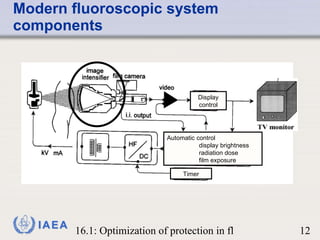
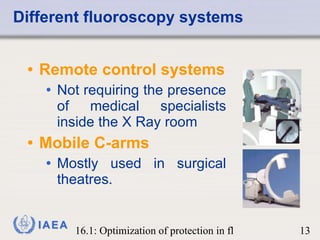
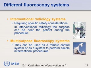
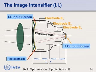
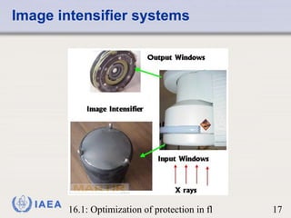
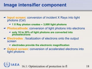
The document summarizes the key components and parameters of fluoroscopy systems. It discusses the image intensifier, which converts x-ray photons into light photons and uses electrodes to focus electrons onto an output screen. Parameters like conversion coefficient, brightness uniformity, and spatial resolution are described. It also covers the image intensifier's connection to a TV system using cameras like vidicons or CCDs, and how this produces a video signal to display fluoroscopy images on a monitor in real-time.


