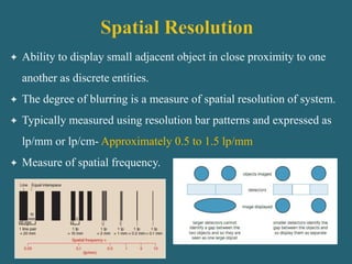
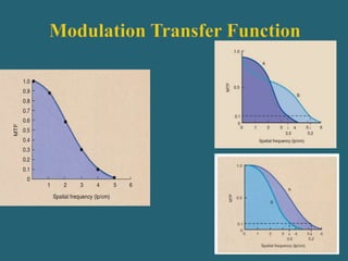
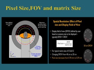
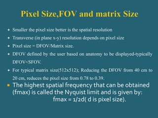
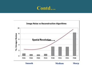
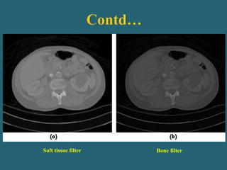
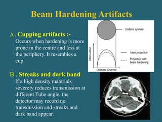
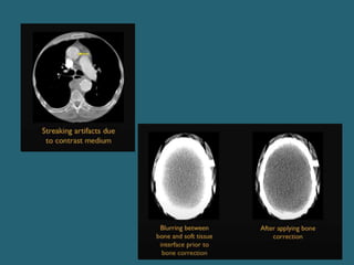
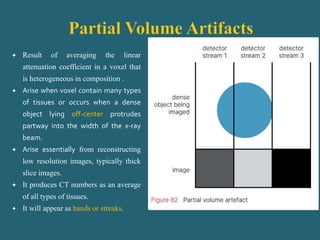
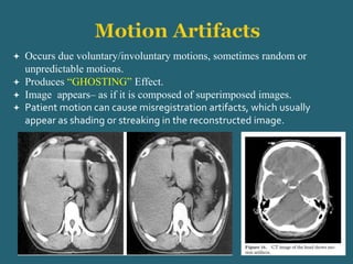
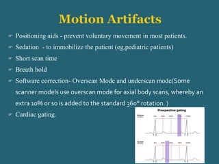
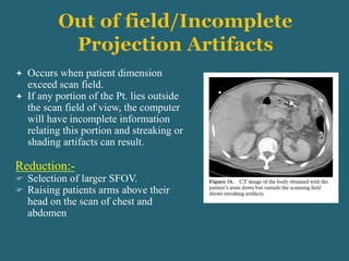
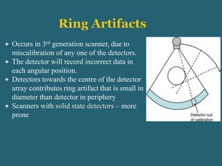
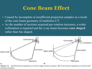
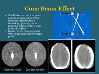
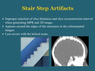
 CT is diagnostic imaging modality which uses x rays to image
individual cross sectional slice through the body.
 The internal structure of an object can be reconstructed from
multiple projections of the object.
 Image quality (clarity) is the visibility of diagnostically
important structure in the CT image.
 An underlying principle of CT, We pay for image quality with
radiation dose.
 Optimized imaging protocols demands that image quality should
be sufficient to meet the clinical requirement for the
examination.
 Image quality in CT depends upon following factors:
Spatial resolution
Contrast resolution
Temporal resolution
Noise
Linearity
Uniformity
Artifacts
 Ability to display small adjacent object in close proximity to one
another as discrete entities.
 The degree of blurring is a measure of spatial resolution of system.
 Typically measured using resolution bar patterns and expressed as
lp/mm or lp/cm- Approximately 0.5 to 1.5 lp/mm
 Measure of spatial frequency.
 Spatial resolution of an image is measured in two
ways:
 Direct method ( by counting the line pair)
 By averaging spread of information within the system
( known as MTF)
 The no. of line pairs per unit length is called spatial frequency.
 The absolute object size that can be resolved is equal to one-half
the reciprocal of the spatial frequency at the limiting resolution.
 Low spatial frequency represents large objects.
 High spatial frequency represents small objects.
 Describes about resolution capacity of an imaging system.
 MTF is the plot of the ratio of image to object contrast (image
fidelity) at each spatial frequency.
 MTF is always less than 1.
 Often measured in two orthogonal directions:
a) Axial (X-Y Plane) Resolution- 0.5 mm
-Determined by image matrix size, DFOV and pixel size.
b) Longitudinal (Z –axis ) resolution- 0.5-0.625 mm
-Determined by detector array thickness.
 X-ray tube focal spot size
 Sampling: detector size (aperture) and sample spacing
(detector pitch)
 Slice thickness.
 Pixel size, Matrix and FOV
 Reconstruction filter
 Patient motion
 Smaller the pixel size better is the spatial resolution
 Transverse (in plane x-y) resolution depends on pixel size
 Pixel size = DFOV/Matrix size.
 DFOV defined by the user based on anatomy to be displayed-typically
DFOV<SFOV.
 For typical matrix size(512x512); Reducing the DFOV from 40 cm to
20 cm, reduces the pixel size from 0.78 to 0.39.
 The highest spatial frequency that can be obtained
(fmax) is called the Nyquist limit and is given by:
fmax = 1/2d( d is pixel size).
 Limiting factor of CT scanner resolution but to a lesser extent
than in radiography
 Larger focal spot(~1mm) causes more geometric unsharpness
and thereby reduces spatial resolution.
 CT scanners frequently operating at high mA can cause
blooming of the focal spot thereby reducing spatial resolution.
 Z flying focal spot is responsible for increase in the cross plane
resolution, by obtaining two overlapping slices for each detector
row.
Detector size (aperture):-
 Width of the active detector element in CT detector array.
 Spatial resolution improves significantly in longitudinal
direction as the detector aperture size decreases.
 In plane (x-y) spatial resolution is not affected.
 In single slice CT, slice thickness equal to beam collimation
 In MDCT, equal to width of the detector in slice thickness
direction.
 Thinner Slices:
Higher Spatial Resolution
Less Partial Volume effects
More Noise
Decreases contrast resolution
a)10 mm b)5 mm c)2.5 mm d)1.25mm
 At same KV and mAs, number of detected photons varies
linearly with slice thickness.
 Thinner slice provides higher spatial resolution but increased
image noise.
 Thicker Slice provides higher contrast resolution but poor
spatial resolution.
 Mathematical filter applied during reconstruction (filtered back
projection) to remove the blur from images.
 Affects spatial resolution but requires tradeoffs depending on
clinical needs.
 Sharp- high spatial resolution but yields greater image noise.
 Soft or Smooth- Reduces image noise but also degrades spatial
resolution.
Smooth Medium Sharp
Soft tissue filter Bone filter
 It is the resolution where the cross-plane resolution (z) match that
of the in-plane (resp.)
 Since in most CT scans the pixel length is considerably smaller
than the slice thickness, the reformatted scan can have an unusual
appearance or stair-step artifact
 Modern MDCT for body imaging has isotropic resolution of
0.8lp/mm.
Advantages :-
 Permits increased visualization of anatomy that do not run
linearly along the z-axis
 Creates MPR images with the same spatial resolution as the
original sections.
 Avoids the need for direct coronal scanning(as in temporal bone)
avoided reducing dose and acquisition time
 Ability of a system to differentiate objects with similar densities
or very slight difference in density on the image.
 Difference in HU values between the tissues.
 How difference is an image from its surrounings?
 CT is far superior in detecting low contrast differences. This is
because of-
-Scatter rejection by pre pt. and pre detector collimators
-Its consideration of the contribution of attenuation coefficient not
only by atomic number differences but also by mass density
differences.
 The contrast between a structure and its surroundings is ONLY
detectable if it is 3-5 times greater than the noise in the image.
 The low contrast resolution of a system is
usually expressed as for example 2mm at
0.5%, which indicates the system can
distinguish structures of 2mm size with their
attenuation difference of 5HU
 CT can detect density differences from 0.25%
to 0.5%, depending on the scanner.
Pixel Size:- If all parameters are fixed ,increase in FOV
increases pixel dimension and the no of x-rays passing
through the pixel thereby increasing CR.
mAs :- By decreasing the mAs(tube current) increases the
image noise and decreases the contrast resolution.
Slice Thickness :-
 Increasing the Slice thickness leads to improved contrast
resolution at the expense of Spatial resolution.
 Decreasing the Slice thickness leads to decreased SNR
and therefore degrades Contrast Resolution(other factors
constant)
Reconstruction Filter:- Bone filter produce lower contrast
resolution and soft tissue filter improves contrast resolution
Patient Size :- For same x-ray technique, larger pt attenuate more
photons resulting in detection of fewer photons causes
reduction in SNR as well as contrast resolution
Gantry Rotation Speed :- Faster the gantry rotation speed lesser
the contrast resolution.
 Random fluctuation of image intensity about some mean value
following uniform exposure.
 Describes the content of an image that limit the ability to visualize low
contrast lesions or pathology.
 X ray images exhibits random variations in a image intensity (Mottle).
 The major types of mottle include quantum mottle, electronic mottle
and computational mottle.
 The dominant source of image mottle:- Quantum mottle.
 Typical noise in CT is ~3 HU.
Quantum Noise
 Random variations of photons incident on a radiation
detectors.
 It is the statistical variation of CT no. of a uniform
object.
 Ideally CT no. at any point on a image of uniform
object should be constant.
 However because of statistical fluctuation , the
variance of CT numbers occurs.
 Measured as standard deviation in CT number
 Characterized by a grainy appearance of the image.
 Depends on number of photons used by the detector to form an
image which depends on several factors:-
 Incident x ray intensity (kVp , mAs and filtration)
 Quantum detection efficiency of detector
 Slice thickness
 Pixel size
 Reconstruction filter or kernel.
 Amount of time taken to acquire single frame of moving object and to
reconstruct an image
 For MDCT it is primarily dependent on the time taken by the scanner
to complete one gantry rotation.
 This improves the temporal resolution to one-half the gantry rotation
time.
 More importantly considered in the context of
cardiac scanning
 Temporal resolution of 100 ms is required for heart
rate of 60 beats per minute
 Gantry rotation time- decrease in gantry rotation time
decreases temporal resolution
 Number of detector channel- increase in detector
channel in z-direction increases temporal resolution
 Reconstruction method- single-segment reconstruction
method has less temporal resolution than multi-segment
reconstruction method
 CT no. should be consistently same
for a particular tissue. Eg.- For
water= 0
 To check linearity, calibration
should be done frequently by
catphan or 5 pin performance test
phantom
 Each of the 5 pins are made up of
diff. plastic material having known
physical and x-ray attenuation
properties
 Plot of CT No. Vs linear
attenuation co-efficient should be
straight line.
 At any time for a uniform phantom, the CT
No. measurement should not change with the
location of the selected region of interest
(ROI) or with the phantom position relative
to the isocentre of the scanner.
 This characteristic of CT system is known as
spatial uniformity.
 Are any errors in the perspection/representation of real objects via any
modalities/techniques
 Artifact is “an unwanted density in an image which may not be present
in the object”.
 Any discrepancy between the reconstructed values in an image and
the true attenuation coefficients of the object.
 CT images are inherently more prone to artifacts because of a million
independent detector measurements.
 Can mimic lesions.
 Significantly degrade CT images.
On the basis of Appearance:
Appearance Cause
Streaks - Improper sampling data, partial volume average, Pt motion, Beam
hardening, Noise, spiral/ helical, Mechanical failure
Shading - Partial volume averaging , Beam hardening, Spiral/ Helical,
Scatter radiation, Off focal radiation , Improper projection
Rings/Bands - Bad detector channel
Streaks Shading Rings/Bands
On the basis of Origin
Physics based-
-Beam Hardening
-Partial volume effect
-Photon starvation
-Under sampling
-Edge gradient artifact
Patient based-
-Metal artifacts
-Motion artifacts
-Out of field
Scanner based-
- Ring Artifacts
- Tube Arcing
Helical and Multisection-
- Cone beam artifacts
- Wind mill Artifacts
Artifacts due to multiplanar and 3-D reformation
- Stair step Artifacts
- Zebra artifacts
 Physics Based Artifacts
Beam hardening artifacts.
Partial volume artifacts.
Photon starvation.
Under sampling
Edge gradient artifact
 Patient based artifacts
 Scanner based artifacts
 Helical & multi-section artifacts.
 Refers to an increase in the mean energy of the x-ray beam as it
passes through the patient
 Caused by polychromatic nature of the beam.
 Low energy photons are preferentially absorbed, beam becomes
more penetrating causing underestimation of the attenuation
coefficient(HU).
A . Cupping artifacts :-
Occurs when hardening is more
prone in the centre and less at
the periphery. It resembles a
cup.
B . Streaks and dark band
If a high density materials
severely reduces transmission at
different Tube angle, the
detector may record no
transmission and streaks and
dark band appear.
 Filtration :- a flat piece of metallic material is used to pre-
harden the beam and also a bow tie filter is used
 Calibration correction :- Scanners are calibrated using
phantoms in a range of sizes
 Beam hardening correction software :-Iterative correction
algorithm may be applied when images of bony regions are
being reconstructed
 By Operator :- avoid scanning bony regions, either by means
of patient positioning or by the tilting the gantry
 Using dual energy ct technique
 Result of averaging the linear
attenuation coefficient in a voxel that
is heterogeneous in composition .
 Arise when voxel contain many types
of tissues or occurs when a dense
object lying off-center protrudes
partway into the width of the x-ray
beam.
 Arise essentially from reconstructing
low resolution images, typically thick
slice images.
 It produces CT numbers as an average
of all types of tissues.
 It will appear as bands or streaks.
 Occurs in highly attenuating
region due to inefficient photons
passing through the widest part of
the patient.
 Manifestation of irregularities
caused by noise in the raw data
profile
 Image appears noisy with streaks
AutomaticTube Current Modulation.
• Multi-dimensionalAdaptive Filtration
• Thicker sections
 Coarse sampling:- Large interval
between projections(undersampling),
results misregisteration of information
within a projection.
 Results view and ray aliasing resp.
 Fine stripes appears in the image
 Aliasing doesn’t have too serious effect
on the diagnostic quality of an image
 Reduction method
Increasing the largest possible no. of projection per rotation.
Using high resolution technique like flying focal spot and
quarter detector shift.
 Arise from irregularly shaped object
that have a pronounced difference in
density from surrounding structure
 Results in streak artifact or shading
How to Minimize??
 Using thinner slices
 Using a low HU- value oral contrast
 Change in patient’s position
 Physics based artifacts
 Patient based artifacts
 Metal artifacts
 Motion artifacts
 Incomplete projections
 Scanner based artifacts
 Helical & multisection artifacts
 Manifest itself as “star streaking” artifact.
 It’s caused by presence of metallic objects
inside or outside the patient.
 Metallic object absorbs the photons causing
an incomplete attenuation profile.
 Reduction methods:-
A. By operator :-
 Taking off removable metal objects before
scanning commences
 Use of gantry angulation
 Increase technique (kv)
 Use thin slices
B. By software correction :-
MAR technique:-
 Acquisition and storage of the raw data
 Reconstruction of CT image
 Identification of the implant
 Automatic definition of the boundaries of the implant within
the projection data. For each projection, the implant boundaries
are automatically defined within the given ROI by the use of
given threshold values
 Iterative reconstruction of the missing projection data
 Reconstruction of the artifact-reduced image from the newly
computed projection data
 Occurs due voluntary/involuntary motions, sometimes random or
unpredictable motions.
 Produces “GHOSTING” Effect.
 Image appears– as if it is composed of superimposed images.
 Patient motion can cause misregistration artifacts, which usually
appear as shading or streaking in the reconstructed image.
 Positioning aids - prevent voluntary movement in most patients.
 Sedation - to immobilize the patient (eg,pediatric patients)
 Short scan time
 Breath hold
 Software correction- Overscan Mode and underscan mode(Some
scanner models use overscan mode for axial body scans, whereby an
extra 10% or so is added to the standard 360° rotation. )
 Cardiac gating.
 Occurs when patient dimension
exceed scan field.
 If any portion of the Pt. lies outside
the scan field of view, the computer
will have incomplete information
relating this portion and streaking or
shading artifacts can result.
Reduction:-
 Selection of larger SFOV.
 Raising patients arms above their
head on the scan of chest and
abdomen
 Physics based artifacts
 Patient based artifacts
 Scanner based artifacts
Ring artifacts
Line in topogram
Tube arcing
 Helical & multisection artifacts.
 Occurs in 3rd generation scanner, due to
miscalibration of any one of the detectors.
 The detector will record incorrect data in
each angular position.
 Detectors towards the centre of the detector
array contributes ring artifact that is small in
diameter than detector in periphery
 Scanners with solid state detectors – more
prone
 Detector calibration
 Detector replacement
 Selecting the correct scan field of view
 Software corrections
 Due to faulty Detectors
Remedy
 Detector replacement
 Occurs when there is a short circuit within the tube, typically from
cathode to tube envelope.
 Tungsten vapor from anode and cathode intercepts the projectile
electrons intended for collisions with the target.
 Causes momentary loss of x-ray output.
Remedy:
 Tube Replacement.
 Physics based artifacts
 Patient based artifacts
 Scanner based artifacts
 Helical & multi-section artifacts.
Cone beam artifacts
Wind mill
 Caused by incomplete or insufficient projection samples as a result
of the cone beam geometry of multislice CT.
 As the number of sections acquired per rotation increases, a wider
collimation is required and the x-ray beam becomes cone shaped
rather than fan shaped.
 Small structure, such as piece
of bone is detected by beam
from one direction but is
missed by opposing beam
resulting inconsistency , leads
to streak artifact
 Such effect is more apparent
with larger cone angle or large
pitch
 More complicated form of axial image distortion.
 Seen in thin slice images reconstructed from high pitch helical
multislice CT images.
 Type of aliasing artifact
 The term wind mill comes from the spiral appearance of shading
artifact.
 Reconstruction techniques like MPR are used that account for
the cone beam angle thereby reducing cone beam artifact
 Pitch <1 can be used
 Z sampling methods used during reconstruction to remove
windmill artifact.
 Physics based artifacts
 Patient based artifacts
 Scanner based artifacts
 Helical & multi-section artifacts.
 Artifacts due to Multiplanar and 3-D
Reformation
Stair Step Artifacts
Zebra Artifacts
 Improper selection of slice thickness and slice reconstruction interval
when generating MPR and 3D image.
 Appears around the edges of the structures in the reformmated
images.
 Less severe with the helical scans .
Remedy:
 Thin slice use
 50% overlap on recon slice incrementation.
 Appears as faint stripes in the multiplanar and 3D reformmated
images from during helical interpolation.
 Becomes more pronounced away from the axis of rotation because
the noise in homogeneity is worse at off-axis
Image Quality And Artifacts in Computed Tomography.pptx

Image Quality And Artifacts in Computed Tomography.pptx

  • 2.
     CT isdiagnostic imaging modality which uses x rays to image individual cross sectional slice through the body.  The internal structure of an object can be reconstructed from multiple projections of the object.
  • 3.
     Image quality(clarity) is the visibility of diagnostically important structure in the CT image.  An underlying principle of CT, We pay for image quality with radiation dose.  Optimized imaging protocols demands that image quality should be sufficient to meet the clinical requirement for the examination.
  • 4.
     Image qualityin CT depends upon following factors: Spatial resolution Contrast resolution Temporal resolution Noise Linearity Uniformity Artifacts
  • 5.
     Ability todisplay small adjacent object in close proximity to one another as discrete entities.  The degree of blurring is a measure of spatial resolution of system.  Typically measured using resolution bar patterns and expressed as lp/mm or lp/cm- Approximately 0.5 to 1.5 lp/mm  Measure of spatial frequency.
  • 7.
     Spatial resolutionof an image is measured in two ways:  Direct method ( by counting the line pair)  By averaging spread of information within the system ( known as MTF)
  • 8.
     The no.of line pairs per unit length is called spatial frequency.  The absolute object size that can be resolved is equal to one-half the reciprocal of the spatial frequency at the limiting resolution.  Low spatial frequency represents large objects.  High spatial frequency represents small objects.
  • 9.
     Describes aboutresolution capacity of an imaging system.  MTF is the plot of the ratio of image to object contrast (image fidelity) at each spatial frequency.  MTF is always less than 1.
  • 11.
     Often measuredin two orthogonal directions: a) Axial (X-Y Plane) Resolution- 0.5 mm -Determined by image matrix size, DFOV and pixel size. b) Longitudinal (Z –axis ) resolution- 0.5-0.625 mm -Determined by detector array thickness.
  • 12.
     X-ray tubefocal spot size  Sampling: detector size (aperture) and sample spacing (detector pitch)  Slice thickness.  Pixel size, Matrix and FOV  Reconstruction filter  Patient motion
  • 14.
     Smaller thepixel size better is the spatial resolution  Transverse (in plane x-y) resolution depends on pixel size  Pixel size = DFOV/Matrix size.  DFOV defined by the user based on anatomy to be displayed-typically DFOV<SFOV.  For typical matrix size(512x512); Reducing the DFOV from 40 cm to 20 cm, reduces the pixel size from 0.78 to 0.39.  The highest spatial frequency that can be obtained (fmax) is called the Nyquist limit and is given by: fmax = 1/2d( d is pixel size).
  • 15.
     Limiting factorof CT scanner resolution but to a lesser extent than in radiography  Larger focal spot(~1mm) causes more geometric unsharpness and thereby reduces spatial resolution.
  • 16.
     CT scannersfrequently operating at high mA can cause blooming of the focal spot thereby reducing spatial resolution.  Z flying focal spot is responsible for increase in the cross plane resolution, by obtaining two overlapping slices for each detector row.
  • 17.
    Detector size (aperture):- Width of the active detector element in CT detector array.  Spatial resolution improves significantly in longitudinal direction as the detector aperture size decreases.  In plane (x-y) spatial resolution is not affected.
  • 18.
     In singleslice CT, slice thickness equal to beam collimation  In MDCT, equal to width of the detector in slice thickness direction.  Thinner Slices: Higher Spatial Resolution Less Partial Volume effects More Noise Decreases contrast resolution a)10 mm b)5 mm c)2.5 mm d)1.25mm
  • 19.
     At sameKV and mAs, number of detected photons varies linearly with slice thickness.  Thinner slice provides higher spatial resolution but increased image noise.  Thicker Slice provides higher contrast resolution but poor spatial resolution.
  • 20.
     Mathematical filterapplied during reconstruction (filtered back projection) to remove the blur from images.  Affects spatial resolution but requires tradeoffs depending on clinical needs.  Sharp- high spatial resolution but yields greater image noise.  Soft or Smooth- Reduces image noise but also degrades spatial resolution.
  • 22.
  • 23.
    Soft tissue filterBone filter
  • 24.
     It isthe resolution where the cross-plane resolution (z) match that of the in-plane (resp.)  Since in most CT scans the pixel length is considerably smaller than the slice thickness, the reformatted scan can have an unusual appearance or stair-step artifact  Modern MDCT for body imaging has isotropic resolution of 0.8lp/mm. Advantages :-  Permits increased visualization of anatomy that do not run linearly along the z-axis  Creates MPR images with the same spatial resolution as the original sections.  Avoids the need for direct coronal scanning(as in temporal bone) avoided reducing dose and acquisition time
  • 25.
     Ability ofa system to differentiate objects with similar densities or very slight difference in density on the image.  Difference in HU values between the tissues.  How difference is an image from its surrounings?  CT is far superior in detecting low contrast differences. This is because of- -Scatter rejection by pre pt. and pre detector collimators -Its consideration of the contribution of attenuation coefficient not only by atomic number differences but also by mass density differences.  The contrast between a structure and its surroundings is ONLY detectable if it is 3-5 times greater than the noise in the image.
  • 26.
     The lowcontrast resolution of a system is usually expressed as for example 2mm at 0.5%, which indicates the system can distinguish structures of 2mm size with their attenuation difference of 5HU  CT can detect density differences from 0.25% to 0.5%, depending on the scanner.
  • 28.
    Pixel Size:- Ifall parameters are fixed ,increase in FOV increases pixel dimension and the no of x-rays passing through the pixel thereby increasing CR. mAs :- By decreasing the mAs(tube current) increases the image noise and decreases the contrast resolution. Slice Thickness :-  Increasing the Slice thickness leads to improved contrast resolution at the expense of Spatial resolution.  Decreasing the Slice thickness leads to decreased SNR and therefore degrades Contrast Resolution(other factors constant)
  • 30.
    Reconstruction Filter:- Bonefilter produce lower contrast resolution and soft tissue filter improves contrast resolution Patient Size :- For same x-ray technique, larger pt attenuate more photons resulting in detection of fewer photons causes reduction in SNR as well as contrast resolution Gantry Rotation Speed :- Faster the gantry rotation speed lesser the contrast resolution.
  • 31.
     Random fluctuationof image intensity about some mean value following uniform exposure.  Describes the content of an image that limit the ability to visualize low contrast lesions or pathology.  X ray images exhibits random variations in a image intensity (Mottle).  The major types of mottle include quantum mottle, electronic mottle and computational mottle.  The dominant source of image mottle:- Quantum mottle.  Typical noise in CT is ~3 HU.
  • 32.
    Quantum Noise  Randomvariations of photons incident on a radiation detectors.  It is the statistical variation of CT no. of a uniform object.  Ideally CT no. at any point on a image of uniform object should be constant.  However because of statistical fluctuation , the variance of CT numbers occurs.  Measured as standard deviation in CT number  Characterized by a grainy appearance of the image.
  • 33.
     Depends onnumber of photons used by the detector to form an image which depends on several factors:-  Incident x ray intensity (kVp , mAs and filtration)  Quantum detection efficiency of detector  Slice thickness  Pixel size  Reconstruction filter or kernel.
  • 34.
     Amount oftime taken to acquire single frame of moving object and to reconstruct an image  For MDCT it is primarily dependent on the time taken by the scanner to complete one gantry rotation.  This improves the temporal resolution to one-half the gantry rotation time.  More importantly considered in the context of cardiac scanning  Temporal resolution of 100 ms is required for heart rate of 60 beats per minute
  • 35.
     Gantry rotationtime- decrease in gantry rotation time decreases temporal resolution  Number of detector channel- increase in detector channel in z-direction increases temporal resolution  Reconstruction method- single-segment reconstruction method has less temporal resolution than multi-segment reconstruction method
  • 36.
     CT no.should be consistently same for a particular tissue. Eg.- For water= 0  To check linearity, calibration should be done frequently by catphan or 5 pin performance test phantom  Each of the 5 pins are made up of diff. plastic material having known physical and x-ray attenuation properties  Plot of CT No. Vs linear attenuation co-efficient should be straight line.
  • 37.
     At anytime for a uniform phantom, the CT No. measurement should not change with the location of the selected region of interest (ROI) or with the phantom position relative to the isocentre of the scanner.  This characteristic of CT system is known as spatial uniformity.
  • 38.
     Are anyerrors in the perspection/representation of real objects via any modalities/techniques  Artifact is “an unwanted density in an image which may not be present in the object”.  Any discrepancy between the reconstructed values in an image and the true attenuation coefficients of the object.  CT images are inherently more prone to artifacts because of a million independent detector measurements.  Can mimic lesions.  Significantly degrade CT images.
  • 39.
    On the basisof Appearance: Appearance Cause Streaks - Improper sampling data, partial volume average, Pt motion, Beam hardening, Noise, spiral/ helical, Mechanical failure Shading - Partial volume averaging , Beam hardening, Spiral/ Helical, Scatter radiation, Off focal radiation , Improper projection Rings/Bands - Bad detector channel
  • 40.
  • 41.
    On the basisof Origin Physics based- -Beam Hardening -Partial volume effect -Photon starvation -Under sampling -Edge gradient artifact Patient based- -Metal artifacts -Motion artifacts -Out of field
  • 42.
    Scanner based- - RingArtifacts - Tube Arcing Helical and Multisection- - Cone beam artifacts - Wind mill Artifacts Artifacts due to multiplanar and 3-D reformation - Stair step Artifacts - Zebra artifacts
  • 43.
     Physics BasedArtifacts Beam hardening artifacts. Partial volume artifacts. Photon starvation. Under sampling Edge gradient artifact  Patient based artifacts  Scanner based artifacts  Helical & multi-section artifacts.
  • 44.
     Refers toan increase in the mean energy of the x-ray beam as it passes through the patient  Caused by polychromatic nature of the beam.  Low energy photons are preferentially absorbed, beam becomes more penetrating causing underestimation of the attenuation coefficient(HU).
  • 45.
    A . Cuppingartifacts :- Occurs when hardening is more prone in the centre and less at the periphery. It resembles a cup. B . Streaks and dark band If a high density materials severely reduces transmission at different Tube angle, the detector may record no transmission and streaks and dark band appear.
  • 47.
     Filtration :-a flat piece of metallic material is used to pre- harden the beam and also a bow tie filter is used  Calibration correction :- Scanners are calibrated using phantoms in a range of sizes  Beam hardening correction software :-Iterative correction algorithm may be applied when images of bony regions are being reconstructed  By Operator :- avoid scanning bony regions, either by means of patient positioning or by the tilting the gantry  Using dual energy ct technique
  • 48.
     Result ofaveraging the linear attenuation coefficient in a voxel that is heterogeneous in composition .  Arise when voxel contain many types of tissues or occurs when a dense object lying off-center protrudes partway into the width of the x-ray beam.  Arise essentially from reconstructing low resolution images, typically thick slice images.  It produces CT numbers as an average of all types of tissues.  It will appear as bands or streaks.
  • 50.
     Occurs inhighly attenuating region due to inefficient photons passing through the widest part of the patient.  Manifestation of irregularities caused by noise in the raw data profile  Image appears noisy with streaks
  • 51.
    AutomaticTube Current Modulation. •Multi-dimensionalAdaptive Filtration • Thicker sections
  • 52.
     Coarse sampling:-Large interval between projections(undersampling), results misregisteration of information within a projection.  Results view and ray aliasing resp.  Fine stripes appears in the image  Aliasing doesn’t have too serious effect on the diagnostic quality of an image
  • 53.
     Reduction method Increasingthe largest possible no. of projection per rotation. Using high resolution technique like flying focal spot and quarter detector shift.
  • 54.
     Arise fromirregularly shaped object that have a pronounced difference in density from surrounding structure  Results in streak artifact or shading How to Minimize??  Using thinner slices  Using a low HU- value oral contrast  Change in patient’s position
  • 55.
     Physics basedartifacts  Patient based artifacts  Metal artifacts  Motion artifacts  Incomplete projections  Scanner based artifacts  Helical & multisection artifacts
  • 56.
     Manifest itselfas “star streaking” artifact.  It’s caused by presence of metallic objects inside or outside the patient.  Metallic object absorbs the photons causing an incomplete attenuation profile.  Reduction methods:- A. By operator :-  Taking off removable metal objects before scanning commences  Use of gantry angulation  Increase technique (kv)  Use thin slices
  • 57.
    B. By softwarecorrection :- MAR technique:-  Acquisition and storage of the raw data  Reconstruction of CT image  Identification of the implant  Automatic definition of the boundaries of the implant within the projection data. For each projection, the implant boundaries are automatically defined within the given ROI by the use of given threshold values  Iterative reconstruction of the missing projection data  Reconstruction of the artifact-reduced image from the newly computed projection data
  • 59.
     Occurs duevoluntary/involuntary motions, sometimes random or unpredictable motions.  Produces “GHOSTING” Effect.  Image appears– as if it is composed of superimposed images.  Patient motion can cause misregistration artifacts, which usually appear as shading or streaking in the reconstructed image.
  • 60.
     Positioning aids- prevent voluntary movement in most patients.  Sedation - to immobilize the patient (eg,pediatric patients)  Short scan time  Breath hold  Software correction- Overscan Mode and underscan mode(Some scanner models use overscan mode for axial body scans, whereby an extra 10% or so is added to the standard 360° rotation. )  Cardiac gating.
  • 61.
     Occurs whenpatient dimension exceed scan field.  If any portion of the Pt. lies outside the scan field of view, the computer will have incomplete information relating this portion and streaking or shading artifacts can result. Reduction:-  Selection of larger SFOV.  Raising patients arms above their head on the scan of chest and abdomen
  • 62.
     Physics basedartifacts  Patient based artifacts  Scanner based artifacts Ring artifacts Line in topogram Tube arcing  Helical & multisection artifacts.
  • 63.
     Occurs in3rd generation scanner, due to miscalibration of any one of the detectors.  The detector will record incorrect data in each angular position.  Detectors towards the centre of the detector array contributes ring artifact that is small in diameter than detector in periphery  Scanners with solid state detectors – more prone
  • 65.
     Detector calibration Detector replacement  Selecting the correct scan field of view  Software corrections
  • 66.
     Due tofaulty Detectors Remedy  Detector replacement
  • 67.
     Occurs whenthere is a short circuit within the tube, typically from cathode to tube envelope.  Tungsten vapor from anode and cathode intercepts the projectile electrons intended for collisions with the target.  Causes momentary loss of x-ray output. Remedy:  Tube Replacement.
  • 68.
     Physics basedartifacts  Patient based artifacts  Scanner based artifacts  Helical & multi-section artifacts. Cone beam artifacts Wind mill
  • 69.
     Caused byincomplete or insufficient projection samples as a result of the cone beam geometry of multislice CT.  As the number of sections acquired per rotation increases, a wider collimation is required and the x-ray beam becomes cone shaped rather than fan shaped.
  • 70.
     Small structure,such as piece of bone is detected by beam from one direction but is missed by opposing beam resulting inconsistency , leads to streak artifact  Such effect is more apparent with larger cone angle or large pitch
  • 71.
     More complicatedform of axial image distortion.  Seen in thin slice images reconstructed from high pitch helical multislice CT images.  Type of aliasing artifact  The term wind mill comes from the spiral appearance of shading artifact.
  • 72.
     Reconstruction techniqueslike MPR are used that account for the cone beam angle thereby reducing cone beam artifact  Pitch <1 can be used  Z sampling methods used during reconstruction to remove windmill artifact.
  • 73.
     Physics basedartifacts  Patient based artifacts  Scanner based artifacts  Helical & multi-section artifacts.  Artifacts due to Multiplanar and 3-D Reformation Stair Step Artifacts Zebra Artifacts
  • 74.
     Improper selectionof slice thickness and slice reconstruction interval when generating MPR and 3D image.  Appears around the edges of the structures in the reformmated images.  Less severe with the helical scans .
  • 75.
    Remedy:  Thin sliceuse  50% overlap on recon slice incrementation.
  • 76.
     Appears asfaint stripes in the multiplanar and 3D reformmated images from during helical interpolation.  Becomes more pronounced away from the axis of rotation because the noise in homogeneity is worse at off-axis